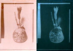
A New Cuprotype?

On the edge of town.

A
On the edge of town.

  • 5
  • 3
  • 71
Peaceful

D
Peaceful

  • 2
  • 11
  • 199
Cycling with wife #2

D
Cycling with wife #2

  • 1
  • 3
  • 85
Time's up!

D
Time's up!

  • 1
  • 1
  • 79

Recent Classifieds

Forum statistics

Threads
198,256
Messages
2,771,775
Members
99,581
Latest member
ibi
Recent bookmarks
0
OP
OP

nmp

Member
Joined
Jan 20, 2005
Messages
2,001
Location
Maryland USA
Format
35mm
What exactly do you mean? I mix soulutions by volume like 1:2:3 but the solutions themselves are prepared by wieght. All relatively fresh.
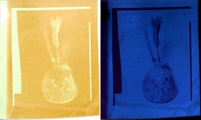
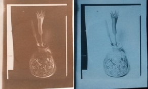
The variation I get is pretty wild. Here is the same paper that I tried during the las couple of weeks. If that's the normal sensitivity of the process to humidity/temperatue/coating then it is unusable and I should give up. But maybe it something else.
I built a special exposure unit for cuprotypes that gives 15 minutes exposure and every time I intend to throw it away I think maybe I should still experiment a bit more.
. View attachment 360494

Never seen such significant variation between test strips processed under identical conditions - unless I deliberately changed the chemistry or processing - within a short span of time. I can't pinpoint what is happening with your process from far so I won't conjecture on what may be happening in your case. I doubt if this process is particularly more or super sensitive to process variables than others out there. @fgorga has printed far more than I with a series of prints, may be he will be able to tell you if this much variation is normal with this process.

The weights I am talking about is first when you prepare each of A, B, and C - my 10% solution for example is 10g of chemical with 90g water. Then when you mix A:B:C by drop counts like 10 drops of A, 15 of B and so on - instead I use 1.0 gram of A, 1.5 g of B, etc. I use squeeze bottles with needle dispensers so the size of a drop is about 0.02g which allows me more accuracy than a glass dropper that is normally used.

:Niranjan.
 

vasya1945

Member
Joined
Aug 21, 2023
Messages
40
Location
Netherlands
Format
DSLR
Also, regarding iron toning, what it is really doing is making cyanotype out of cuprotype (or copper toned cyanotype) so longevity presumably would be expected to be no different from a regular cyanotype.
Do you mean that with iron toner prussian blue is produced? If so the colors I get is what you'd expect from mixing blue and brown . That's good news, we have reasonably stable brown prints. I'd rather make theese than VDB's.

And what about citric acid toner? What does it do?
 
OP
OP

nmp

Member
Joined
Jan 20, 2005
Messages
2,001
Location
Maryland USA
Format
35mm
Do you mean that with iron toner prussian blue is produced? If so the colors I get is what you'd expect from mixing blue and brown . That's good news, we have reasonably stable brown prints. I'd rather make theese than VDB's.

Right.

And what about citric acid toner? What does it do?

With any acid, the theory is that it breaks down residual thiosulfate to produce colloidal sulfur which forms darker copper sulfides in the paper which are fairly stable too.

:Niranjan.
 
Joined
Dec 29, 2018
Messages
982
Location
USA
Format
Traditional
I built a special exposure unit for cuprotypes that gives 15 minutes exposure and every time I intend to throw it away I think maybe I should still experiment a bit more.

'Just printing' rather than focusing on super DMax and nailing 100% reproducibility might serve to bring some enjoyment back into the process for you. Build up a collection of suitable negatives over time and print a subset each time you have a coating session. Not every coating or print will be acceptable but eventually you're bound to produce some prints that are exceptional.

I'd rather have a bad print of a negative than a step wedge with good DMax 😀
 
Joined
Dec 29, 2018
Messages
982
Location
USA
Format
Traditional
I mixed 25mL of sensitizer and gravity coated it onto some canson watercolor. No proper exposure unit or sunlight, so I used a DLP projector's blue channel to contact print a 4x5 positive into a paper negative.

Inversion and scan of the toned print.

cuprotype_diposprints.jpg

I've got 3 more sheets of this size but the lack of a proper UV source is a pain. There was probably a stop of density lost to underexposure here.
 

vasya1945

Member
Joined
Aug 21, 2023
Messages
40
Location
Netherlands
Format
DSLR
I've got 3 more sheets of this size but the lack of a proper UV source is a pain. There was probably a stop of density lost to underexposure here.
If you do 4x5 than you can get one of these chinese ligh sources. Led assembly size is 16x22cm, so you can put it pretty close to the negative so no light is lost. In my experiments it gave around 20mins exposure (to the point where uncovered paper and film covered part burn to the same density). The thing gets hot but at least doesn't melt.
Screenshot 2024-01-20 111316.png
 

koraks

Moderator
Moderator
Joined
Nov 29, 2018
Messages
21,956
Location
Europe
Format
Multi Format
If you do 4x5 than you can get one of these chinese ligh sources.

Those are good value, generally. I use them all the time; currently the 365+395nm dual wavelength type. You need to remove the transparent plastic front cover to allow the 365nm wavelength to pass. With pure 395nm this is not necessary.
You can gang up several of these in a grid to cover a larger area. I've got 4 in a 2x2 matrix and I expose 8x10 with that all the time. Not cuprotype, but other processes, but that doesn't matter in terms of coverage.
 

vasya1945

Member
Joined
Aug 21, 2023
Messages
40
Location
Netherlands
Format
DSLR
Those are good value, generally. I use them all the time; currently the 365+395nm dual wavelength type. You need to remove the transparent plastic front cover to allow the 365nm wavelength to pass. With pure 395nm this is not necessary.
You can gang up several of these in a grid to cover a larger area. I've got 4 in a 2x2 matrix and I expose 8x10 with that all the time. Not cuprotype, but other processes, but that doesn't matter in terms of coverage.

I only have two. I was thinkig of having 4, but with 4 there will be a gap (bezels are thick on short side) and then I'll have to move them a bit away and some light will be lost. For other procecess it's not a problem, but cuprotypes exposure can get too long. And I couldn't make cuprotypes work anyway. I discovered that they sell bare led boards from these lights for $15. So tiling 4 to cover 30x40 is around 60, which is the highest watt to money ratio I could find.
If anyone is intrested real power of these is 100w. Chinese sellers never state correct power. I think you can get it by just multiplying the number of leds by 0.5W
 

koraks

Moderator
Moderator
Joined
Nov 29, 2018
Messages
21,956
Location
Europe
Format
Multi Format
with 4 there will be a gap (bezels are thick on short side)

Yes, that's true, but it doesn't require much distance to get even exposure. My working distance between the LEDs and the actual print is about 20cm. The widest gap between the LEDs due to the bezels on my setup is about 9cm.

I discovered that they sell bare led boards from these lights for $15.

Oh, that's neat! But how about thermal management? The units I have get very hot indeed, and that's with the metal enclosure/backing plate which acts has a heat sink. Without this, the LEDs would burn out, I'm quite sure. You'd have to mount these led boards onto a suitable heat sink.

If anyone is intrested real power of these is 100w.

That's also my experience. I tested the generic 300W types and found they're around 75W in reality.

I think you can get it by just multiplying the number of leds by 0.5W

Yes, that's correct. I approximated it in 3 different ways (circuit analysis, RMS power measurement and multiplying LEDs * nominal LED power) and the figures agreed quite nicely with each other.
 
OP
OP

nmp

Member
Joined
Jan 20, 2005
Messages
2,001
Location
Maryland USA
Format
35mm
If you do 4x5 than you can get one of these chinese ligh sources. Led assembly size is 16x22cm, so you can put it pretty close to the negative so no light is lost. In my experiments it gave around 20mins exposure (to the point where uncovered paper and film covered part burn to the same density). The thing gets hot but at least doesn't melt.
View attachment 360570

20 minutes is pretty good for cuprotypes.

I bought one of these in the 365nm flavor. Then I measured what is happening to the intensity (with a UV meter I have measuring primarily at 360 nm) as you turn on and found that intensity decreased drastically losing about 50% within about 15 minutes. at which point I stopped. The unit also became burning hot in the back. And the intensity itself was not better than my current spiral BLB based unit. So I returned that unit. I guess I bring this up because we were taking about variability in the the process - as this could be one. With my spiral BLB's, it takes about 4 minutes to come to some sort of equilibrium (goes up immediately as you switch it on and then goes down until it reaches a plateau after which it is more or less constant.) So I warm up the bulbs by switching them on for 4 minutes before making an exposure. Just one more thing to worry about.... 🙂

:Niranjan.
 
Last edited:

vasya1945

Member
Joined
Aug 21, 2023
Messages
40
Location
Netherlands
Format
DSLR
But how about thermal management?
I was mounting them on a plate and cooling with external fans. My experiments were not progressing and I was only printing test strips. So I assembled the fixture back. Now I use it in it's original shape but still keep external fans on. Inside the led pcb is only touching metal surface in some spots, it was not glued over the entire are. And the casing is thin and without ribs. So I don't think you'd make matters worse with mounting on a plate, maybe even better if you could add thermal paste. But that was only for cuprotypes where you need like at least 5x the power. For other process not worth the hassle imo.
I bought one of these in the 365nm flavor. Then I measured what is happening to the intensity (with a UV meter I have measuring primarily at 360 nm) as you turn on and found that intensity decreased drastically losing about 50% within about 15 minutes.
I think this is heat issues. I never dared to run those without some form of cooling. Even a household fan makes them less hot, at least not hot to touch.
But specifically this desing of fixtures is terrible.
I also compared ~100w facial tanner with ~100w led projector (365nm even so itj'sv also "real" UV) and found that exposure times are comparable. You won't get much just by swithching to led in terms of raw power. So if your fluorescent lightbox works I would not even bother. If you get 40 minutes of cuptotypes that's perfectly workable. I think pushing beyond 15-20 mins is difficult if not impossible.
 

koraks

Moderator
Moderator
Joined
Nov 29, 2018
Messages
21,956
Location
Europe
Format
Multi Format
So I don't think you'd make matters worse with mounting on a plate

I wouldn't recommend it. I've done quite a few projects with self-made LED light sources on alu-core PCB's. Based on that experience, I wouldn't run these particular PCB's without their metal casing, which really does add significantly to the dissipating ability of the fixture as a whole.

You won't get much just by swithching to led in terms of raw power.

It depends a bit on the process and its peak sensitivity. The main advantage of LED, for me, is the better collimation vs. tubes. For metal-based processes, this may not matter much, although the difference is sometimes visible even to the naked eye. For processes with thick media like carbon transfer, it's a relevant difference.
 
Joined
Dec 29, 2018
Messages
982
Location
USA
Format
Traditional
Same paper (a day old) but with a thinner positive (+1 stop) and a more powerful exposure of 45 minutes (240W DLP @ 12 inches; but surely the micromirrors and UV coatings make the effective power much lower). Probably a bit over-exposed here, though.

Since the original bit of film was a positive, I've included the inversion of each print scan for reference.

Scan directly after exposure (no washing)
cutyp_exposure_nps.jpg

Scan after washing and toning in CuSO4/Citrate/Ferricyanide
cutyp_CuCitFerriCN_nps.jpg

I'll probably snip off the bottom edge and give some 2nd toner experimentation a try.
 
OP
OP

nmp

Member
Joined
Jan 20, 2005
Messages
2,001
Location
Maryland USA
Format
35mm
Same paper (a day old) but with a thinner positive (+1 stop) and a more powerful exposure of 45 minutes (240W DLP @ 12 inches; but surely the micromirrors and UV coatings make the effective power much lower). Probably a bit over-exposed here, though.

Since the original bit of film was a positive, I've included the inversion of each print scan for reference.

Scan directly after exposure (no washing)
View attachment 360622

Scan after washing and toning in CuSO4/Citrate/Ferricyanide
View attachment 360623

I'll probably snip off the bottom edge and give some 2nd toner experimentation a try.

Very interesting. Could you not use a blue digital negative straight from the computer and project it to get it to print?

:Niranjan.
 
Joined
Dec 29, 2018
Messages
982
Location
USA
Format
Traditional
I used a white screen as a 'dumb' light source for contact printing the above. I've gotten good results with cyanotype & salt prints in the past with direct digital projection but haven't tried it with a cuprotype. It should work, in theory.

And just for comparison, an untoned 'new' formula cyanotype of the same positive, same paper (but acidified), ~30 minute exposure.
 

Attachments

  • ncyano_poss.jpg
    ncyano_poss.jpg
    384.8 KB · Views: 63
Joined
Dec 29, 2018
Messages
982
Location
USA
Format
Traditional
One more quick example this evening to use up my last scraps of coated paper.

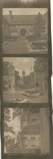
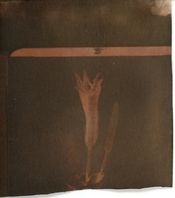
After simple ferricyanide toning, rinse, and optionally drying; immerse the print in a *very* dilute solution of silver nitrate for several minutes and rinse well. Mild bleaching of the image occurs but will be developed back in the next step by immersing the print in a *very* dilute film/paper developer.

The silver seems to prefer the copper compounds and will develop out to some extent, altering the tone of the image. It didn't help (or hurt) with contrast in this case but a lot of that is down to choice of some random 6x6 negatives.

(both unedited scans)

cupro_agdevs.jpg

I had earlier chopped up the first print (from post #105), tried this, and got much more speed, Dmax, and highlight fog. These are from the same coating batch so it goes to show how some subtle variations can produce interesting results.

img311.jpg
 
OP
OP

nmp

Member
Joined
Jan 20, 2005
Messages
2,001
Location
Maryland USA
Format
35mm
One more quick example this evening to use up my last scraps of coated paper.

After simple ferricyanide toning, rinse, and optionally drying; immerse the print in a *very* dilute solution of silver nitrate for several minutes and rinse well. Mild bleaching of the image occurs but will be developed back in the next step by immersing the print in a *very* dilute film/paper developer.

The silver seems to prefer the copper compounds and will develop out to some extent, altering the tone of the image. It didn't help (or hurt) with contrast in this case but a lot of that is down to choice of some random 6x6 negatives.

(both unedited scans)

View attachment 360638

I had earlier chopped up the first print (from post #105), tried this, and got much more speed, Dmax, and highlight fog. These are from the same coating batch so it goes to show how some subtle variations can produce interesting results.

View attachment 360639

You are basically replacing copper with silver making silver ferrocyanide which on develop gives silver image. Interesting, but a longer way to get a developed out salt print!

:Niranjan.
 
Joined
Dec 29, 2018
Messages
982
Location
USA
Format
Traditional
You are basically replacing copper with silver making silver ferrocyanide which on develop gives silver image. Interesting, but a longer way to get a developed out salt print!

Yep, it is likely a combo copper/silver image at this point. The silver treatment was very mild so most of the copper image remained. This doesn't appear to work with the 'complex' toner which perhaps points to better image stability. I wonder if the residual silver in used fixer might show a similar effect.

I wonder if it is practical to make positive cyanotype from your negative...

In theory sure, but I actually tried this and the cuprotype paper (canson watercolor 300gsm) was simply too thick to allow for a proper exposure. The inverse colors of the two prints are a fun concept.

I coated some glossy canon photo paper but have yet to expose any of it.
 
Joined
Dec 29, 2018
Messages
982
Location
USA
Format
Traditional
The glossy photo papers were a bust. The exposure is discernable but doesn't persist through washing and toning. I also coated a sheet of semi-gloss photo paper which managed to produce an image with its higher surface area.

Printed via projected digital negative of the cyanotype above; simple toner.
Unadjusted print scan & inversion.

dlp_cupro_semigloss_bwcyanoneg_p.jpg
 
OP
OP

nmp

Member
Joined
Jan 20, 2005
Messages
2,001
Location
Maryland USA
Format
35mm
Yep, it is likely a combo copper/silver image at this point. The silver treatment was very mild so most of the copper image remained. This doesn't appear to work with the 'complex' toner which perhaps points to better image stability. I wonder if the residual silver in used fixer might show a similar effect.

Yeah, should have said silver-toned cuprotype, as opposed to copper-toned silver which uses almost the same toner as the "complex" toner. Now if you used the spent fixer, we will be where we started, the circle will be complete and @Jan de Jong will be happy....🙂

:Niranjan
 

koraks

Moderator
Moderator
Joined
Nov 29, 2018
Messages
21,956
Location
Europe
Format
Multi Format
I bought one of these in the 365nm flavor. Then I measured what is happening to the intensity (with a UV meter I have measuring primarily at 360 nm) as you turn on and found that intensity decreased drastically losing about 50% within about 15 minutes. at which point I stopped. The unit also became burning hot in the back.

Because I have a UV meter hooked up to my light source anyway (I just never use it...), I figured I could also track the actual UV output of mine. Heres what the plot looks like:
1706175114538.png

It's fairly consistent to your findings, although the light loss is only around a third of the initial output. After about 15 minutes the output has settled mostly.
Like yours, my unit also gets quite hot, but I don't mind. I've been using this particular setup quite intensively for months now with exposures lasting up to 45-60 minutes. It works very well; I'm quite happy with it.
 
OP
OP

nmp

Member
Joined
Jan 20, 2005
Messages
2,001
Location
Maryland USA
Format
35mm
Because I have a UV meter hooked up to my light source anyway (I just never use it...), I figured I could also track the actual UV output of mine. Heres what the plot looks like:
View attachment 361088
It's fairly consistent to your findings, although the light loss is only around a third of the initial output. After about 15 minutes the output has settled mostly.
Like yours, my unit also gets quite hot, but I don't mind. I've been using this particular setup quite intensively for months now with exposures lasting up to 45-60 minutes. It works very well; I'm quite happy with it.

I am sure if I had used a fan directly over it, it would have changed the amount of drop off. Perhaps my unit just didn't have adequate cooling features. This is how similar measurements look like on my unit with 18 CFL spiral BLB bulbs in a 12x16 space fitted with one of those computer exhaust fans.

UVBoxTime vs Intensity.png


The green line is for warm up where it shows about 4 minutes or so (top x-axis) is enough to come to a plateau. The black line (bottom x axis) is for readings after 4 minutes of warm up followed by 5 minutes of rest. This would be important if the exposures are in the range of 10 minutes or less. For longer exposure perhaps the initial period is not that material.

:Niranjan.
 

vasya1945

Member
Joined
Aug 21, 2023
Messages
40
Location
Netherlands
Format
DSLR
Perhaps my unit just didn't have adequate cooling features
I think your curve comes from amalgama heating inside the cfls. I'd give it a couple of minutes for mecrury concentration to stabilize.
The led units I posted are pretty bad inside. There is like 5cm blob of glue for 20x25 board. That the only spot of contact with casing. But still fan seems to lower its temperature. I think when I mount pcb from these lamps onto a metal palte I can improve thermal contact(more thermal paste) and thus improve external cooling.
 

koraks

Moderator
Moderator
Joined
Nov 29, 2018
Messages
21,956
Location
Europe
Format
Multi Format
This is how similar measurements look like on my unit with 18 CFL spiral BLB bulbs in a 12x16 space fitted with one of those computer exhaust fans.

I've not tested my UV BL tubes, but I haven't used them for months, anyway. The LEDs, despite this shortcoming, are so far superior in terms of sharpness of the prints that I'm probably not going to bother with tubes anymore.
 
Photrio.com contains affiliate links to products. We may receive a commission for purchases made through these links.
To read our full affiliate disclosure statement please click Here.

PHOTRIO PARTNERS EQUALLY FUNDING OUR COMMUNITY:


Ilford ADOX Freestyle Photographic Stearman Press Weldon Color Lab Blue Moon Camera & Machine
Top Bottom