Minolta 5400 Mark 1 - ZigZag artefacts

Water from the Mountain

A
Water from the Mountain

  • 2
  • 0
  • 30
Rijksmuseum Amsterdam

A
Rijksmuseum Amsterdam

  • 0
  • 0
  • 29
Lotus

A
Lotus

  • 4
  • 0
  • 47
Magpies

A
Magpies

  • 4
  • 0
  • 83
Abermaw woods

A
Abermaw woods

  • 5
  • 0
  • 78

Recent Classifieds

Forum statistics

Threads
197,520
Messages
2,760,483
Members
99,394
Latest member
Photogenic Mind
Recent bookmarks
0

albireo

Member
Joined
Nov 15, 2017
Messages
1,250
Location
Europe
Format
Multi Format
I doubt something is wrong with your scanner. It's in line with what others are seeing and I don't think all the scanners have rotten by now. This site (Italian) has the best test of Minolta 5400 (I and II) ever made and also has Nikon 8000 test. If you check the samples and lift the shadows heavily you can see similar noise and scanners were relatively new at the time of test.

Have only been able to quickly scan the article, but the review claims the issue happens with a combination of multisampling, grain dissolver and ICE?

I used none of the three above and found the band in my last example to show noise. Is it the same issue or just standard thermal noise-derived patterns?
 

koraks

Moderator
Moderator
Joined
Nov 29, 2018
Messages
20,858
Location
Europe
Format
Multi Format
Actually, it's probably the most sensible solution. I've been looking at small led light source with hight CRI. Less heat, stable light, possibly less noise. It shouldn't be a difficult mod and it might bring additionnal benefits.

Yeah, that would be an interesting approach for sure. I wouldn't stare myself bind on the CRI either. 90-95 is easy to get and will likely do fine. Keep in mind the sensor sees only spectral peaks of R, G and B anyway. As long as those are there in sufficient amounts, you'll be OK.

Is it the same issue or just standard thermal noise-derived patterns?

Partly thermal for the random noise part, but the wavy thing is evidently caused by injection of noise from something like a motor driver or just plain power supply noise.
 

brbo

Member
Joined
Dec 28, 2011
Messages
2,025
Location
EU
Format
Multi Format
I am not sure I see the same thing. With multisampling their test images show almost no noise whereas the zigzag effect is even more pronounced with multisample enabled.

No, it's not more pronounced with multisampling. It's less pronounced. When grain dissolver is disabled.

Also, and as stated before I've scanned the same image with the same scanner at different stages of its life, and the scans from 2015 do not show the same patterns. We are running circles here.

I'm not disputing your observations. I'm just saying that I don't believe ALL scanners have degraded.

For example, @scarbantia thought that his scanner started producing a LOT of noise overnight, then it turned out that previous scans are comparable to the new scans. @albeiro thought his scanner had supper clean shadows, turns out it's comparable to other 5400s. I can see a pattern here...

I wouldn't exclude the possibility that current problems are related to changes in operating systems and driver software.

I have tested this scanner on equipment predating the scanner all the way to the modern computers. With OEM software, Silverfast and Vuescan. Vuescan can be a bit of a hit and miss with scanners, but Minolta 5400 support in Vuescan is done properly.

Have only been able to quickly scan the article, but the review claims the issue happens with a combination of multisampling, grain dissolver and ICE?

I used none of the three above and found the band in my last example to show noise. Is it the same issue or just standard thermal noise-derived patterns?

We know the grain dissolver introduces a big amount of noise. That has been verified on every Minolta 5400 so far (maybe someday a 5400 without this problem will surface, but lets assume that this is generally true for now). I believe Fernando (author of the test I linked to) did most of his tests with OEM Minolta Scan software where enabling ICE implicitly enables GD (you can't have ICE without GD in OEM software; they are not linked in Vuescan and Silverfast though).

What I believe happens is that GD introduces a lot of noise (most of it comes from the sensor itself (thermal noise) since GD requires much longer exposure time, but as @koraks says there is obviously also a second source of noise). If you then enable multisampling, that will clean the colour noise in shadows and you will notice jaggies more easily since there is less colour noise to mask the high contrast transitions.

That's why my proposal was to scan black frame, change exposure, GD, multisampling parameters to see the most prominent offender and to compare out scanners. I forgot to upload my samples yesterday, but they are a bit worse than yours (so, your scanner is at least better than mine 🙂). It could also be down to other factors (temperature of sensor at calibration time, scan time, other interferences...).

Yeah, that would be an interesting approach for sure. I wouldn't stare myself bind on the CRI either. 90-95 is easy to get and will likely do fine. Keep in mind the sensor sees only spectral peaks of R, G and B anyway. As long as those are there in sufficient amounts, you'll be OK.

Do off the shelf LEDs typically go into IR spectrum enough to keep the ICE functionality of the scanner?

BTW, Minolta 5400 II produced worse IQ with LED light source. Presumably because they needed to increase sensor gain to increase scanning speed (LED brightness was not better than CCFL). I believe that LEDs have come a long way since then so the luminosity per W should be better now, right?

5400 II also had huge problems with LED light source uneveness. If today's LEDs are bright enough an additional diffuser could be employed. Space permitting, of course...
 
Last edited:

scarbantia

Member
Joined
Jan 22, 2025
Messages
23
Location
Hungary
Format
35mm
I've never had a good experience with Vuescan. I have tried again. Are these vertical bands normal?
 

Attachments

  • vue0002_test.jpg
    vue0002_test.jpg
    524.2 KB · Views: 28

brbo

Member
Joined
Dec 28, 2011
Messages
2,025
Location
EU
Format
Multi Format
No, not normal. Since they are vertical it can't be because of poor calibration. It could be transport problem, but I guess SF never gives you this problem... 🤷‍♂️
 

albireo

Member
Joined
Nov 15, 2017
Messages
1,250
Location
Europe
Format
Multi Format
I think there is huge variability in the extent of these issues.

I also wonder if extreme densities of the scanned material are a factor here. Can people post a photograph of the negatives they're using? Does the problem only happen with very dense, perhaps underexposed slides?

I've decided I want to try to understand if the pattern I see scanning brbo's opaque material is down purely to this being a 'stress test' - something the scanner is not designed to do.

Do I see any abnormalities in the material I use the scanner for?

I don't shoot slides at the moment, so the scanner's behaviour with slides is of no relevance to me. 90% of my images are black and white negatives.

Here's a quick 'edge case' for me. This was a very contrasty roll, for my standards. Mild underexposure combined with pretty severe overdev. Foma 200 in Fomadon LQN, and by mistake I ended up developing for a target gamma of .65. My standard target gamma is in the region of 0.55.

Here's the full frame - Vuescan, 16bit/channel - grayscale (green channel selected) - AF - raw - linear inversion + gamma correction. 1X multisampler and GD = off.

bkUqqjl.jpg


100% detail including densest highlight region

2WTKDWi.jpg


Same region, 6X multisampling

t3r1baw.jpg


Same region, 6x multisampling + Grain Dissolver

IDm1Nyi.jpg


I'm not seeing any trace of a zig-zag pattern or any other source of gross non random noise, both in the 1:1 details, and in the monitor-size full image. I haven't tried to print this yet but I will.

On top of that, I do not see, for this more challenging (compared to my baseline) b&w negative any appreciable difference between 1X, 6X and no-gd vs gd. Maybe - I can detect a perhaps tiny decrease in sharpness in the 6x+GD sample.

I don't have a slide film frame to try here, and this definitely needs way more systematic testing, but I'm pretty happy in that I think my copy of the device works within acceptable technical tolerances.
 
Last edited:

koraks

Moderator
Moderator
Joined
Nov 29, 2018
Messages
20,858
Location
Europe
Format
Multi Format
Do off the shelf LEDs typically go into IR spectrum enough to keep the ICE functionality of the scanner?

That's a good point; no, I don't think so. I would propose to add another LED or array of LEDs for the IR part of the spectrum.
With today's LED technology it's undoubtedly possible to match or exceed the quality of the original CFL in terms of output and evenness.

I also wonder if extreme densities of the scanned material are a factor here. Can people post a photograph of the negatives they're using? Does the problem only happen with very dense, perhaps overexposed slides?

The problem insofar I've seen it is/was with slides, and the dark areas, so underexposed slides would be the worst. I don't see how this issue would conceivable play a big role with B&W let alone color negatives because those don't even come close in terms of density.

Foma 200 in Fomadon LQN, and by mistake I ended up developing for a target gamma of .65. My standard target gamma is in the region of 0.55.

Yeah, so you're evaluating densities well below 2.0logD here. The problems exist with densities >3.0logD. That's a different world altogether.
 

albireo

Member
Joined
Nov 15, 2017
Messages
1,250
Location
Europe
Format
Multi Format
The problem insofar I've seen it is/was with slides, and the dark areas, so underexposed slides would be the worst. I don't see how this issue would conceivable play a big role with B&W let alone color negatives because those don't even come close in terms of density.

Ops - sorry. Yes of course I meant underexposed slides. Amended.

Yeah, so you're evaluating densities well below 2.0logD here. The problems exist with densities >3.0logD. That's a different world altogether.

Exactly. Then I'll see myself out and apologies for polluting the thread.
 
Last edited:

Crysist

Member
Joined
Aug 3, 2012
Messages
71
Location
New York
Format
Multi Format
Practical answer: no. It would involve basically a complete redesign of the electronics. Might as well replace the light source with something modern as well while you're at it. And perhaps have a look at the optics. Heck, why not dump the whole think and build a new one? That's what you'd end up doing.
One of the key bottlenecks is that it's unlikely to find a pin-compatible, instruction-compatible drop-in replacement for this ADC with better noise performance. So you'd be re-designing the PCB (or making some kind of Frankenstein piggy-back device) as well as implanting a new processor with newly made software into the thing at the very least. Which is a gargantuan task in itself.

Oh uh, right... I wasn't implying all that other stuff, just individual things on the level that @scarbantia had done, and might need to do if, say, the light dies. I have no personal knowledge of whether ADCs are interchangeable, but I thought it'd be possible to some extent. I'd gotten the impression there was more malleability from watching a bunch of restoration/hobbyist types do so in videos. I have no knowledge on electronics though, so please excuse me if I'm just suggesting silly stuff and don't recognize it... 😅
 

scarbantia

Member
Joined
Jan 22, 2025
Messages
23
Location
Hungary
Format
35mm
No, not normal. Since they are vertical it can't be because of poor calibration. It could be transport problem, but I guess SF never gives you this problem... 🤷‍♂️

Luckily, Silverfast 8.8 gives me a nice even result! Oh, and a few zigzags... :tongue:
 

scarbantia

Member
Joined
Jan 22, 2025
Messages
23
Location
Hungary
Format
35mm
Nikon Coolscan zigzag noise and how to fix it.

The Coolscan 9000ED and 5000ED use the same AD9826 converter as the Minolta 5400.
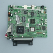
This is the main board of the Minolta 5400, but the ADC chip is on the CCD board, next to the CCD:
s-l1600.jpg
After the ADC converter, can the scanner pick up noise?

--
Does anyone know what wavelengths the color filters on the CCD sensor?
Or does anyone know the exact type of CCD sensor?
 

koraks

Moderator
Moderator
Joined
Nov 29, 2018
Messages
20,858
Location
Europe
Format
Multi Format
The Coolscan 9000ED and 5000ED use the same AD9826 converter as the Minolta 5400.

Quite possible. But noise performance depends on more factors than the chip used, and those factors are generally of a much bigger influence. So it cannot be expected that these scanners will all have the same noise performance, nor the same failure modes over time.

This is the main board of the Minolta 5400, but the ADC chip is on the CCD board, next to the CCD:

Indeed, so the image shown isn't very relevant as it omits the critical part around the ADC and CCD. Photos of that area were posted earlier in this thread.

After the ADC converter, can the scanner pick up noise?
Yes, but as @Anon Ymous this is exceedingly less likely and it'll look totally different from what's seen in the examples in this thread.

Does anyone know what wavelengths the color filters on the CCD sensor?

I don't expect this to be very critical if you're considering replacing the light source, since red, green and blue usually group around 450nm, 540nm and 650nm respectively, with a very generous allowance on either side of the peak (it's a pretty broad bell curve usually). The main question is at around which wavelength the IR acquisition is done, but I expect any normal 940nm IR LED would fit the bill just fine.
 
OP
OP

Archiloque

Member
Joined
Mar 31, 2015
Messages
61
Location
France
Format
35mm
Speaking of the 9000, and for completion sake, here is a picture of a spare 9000 CCD I have laying around.

The culprit in that case is C18.

Not that it really helps us in any case, but who knows...

P1016684.jpg
 

koraks

Moderator
Moderator
Joined
Nov 29, 2018
Messages
20,858
Location
Europe
Format
Multi Format
The culprit in that case is C18.

Yes, that makes good sense. Note how C18 is part of the filter circuit around the CAPT and CAPB pins, which set a reference voltage. Any noise on a reference voltage will affect the output severely. Note that this section of the circuit in the Minolta 5400 is largely obscured by the connector between the CCD PCB and the mainboard.
 

scarbantia

Member
Joined
Jan 22, 2025
Messages
23
Location
Hungary
Format
35mm
Quite possible. But noise performance depends on more factors than the chip used, and those factors are generally of a much bigger influence. So it cannot be expected that these scanners will all have the same noise performance, nor the same failure modes over time.

Yes, the problem is not the AD converter, just interesting.

Indeed, so the image shown isn't very relevant as it omits the critical part around the ADC and CCD. Photos of that area were posted earlier in this thread.
Yes I see, but then the problem is concentrated on that component.

I don't expect this to be very critical if you're considering replacing the light source, since red, green and blue usually group around 450nm, 540nm and 650nm respectively, with a very generous allowance on either side of the peak (it's a pretty broad bell curve usually). The main question is at around which wavelength the IR acquisition is done, but I expect any normal 940nm IR LED would fit the bill just fine.

I think the wide overlap RGB spectral distribution is a problem for colour separation. But if I use narrow spectral peaks for backlighting, I get better results. Most modern cameras are worse at this than old scanners.
 

koraks

Moderator
Moderator
Joined
Nov 29, 2018
Messages
20,858
Location
Europe
Format
Multi Format
then the problem is concentrated on that component.

No, that's not accurate. It's where the problem manifests itself and it's related to the ADC. This doesn't mean it's isolated to the ADC. In fact, it virtually certainly isn't.


I think the wide overlap RGB spectral distribution is a problem for colour separation.

Depends. The special purity of a commonly used dichroic enlarger in combination with RA4 paper is pretty abysmal by this kind of standard, and yet, we like the prints.
A lot depends also on signal processing; this is pertinent in your digital camera example.
Spectral sensitivity of the sensor is just one aspect and by itself, it doesn't say all that much.
 
OP
OP

Archiloque

Member
Joined
Mar 31, 2015
Messages
61
Location
France
Format
35mm
Yes, that makes good sense. Note how C18 is part of the filter circuit around the CAPT and CAPB pins, which set a reference voltage. Any noise on a reference voltage will affect the output severely. Note that this section of the circuit in the Minolta 5400 is largely obscured by the connector between the CCD PCB and the mainboard

When you changed the capacitor in my scanner, was the capacitor in question related to the CAPT CAPB pins of the ADC?

EDIT : answering my own question. Yes you did.

I tried to a few pictures of the line sensor board. I found an electrolyte at the back of the PCB (C42) with a value of 10mf and 16v that matches the faulty electrolyte of the coolscans. Unfortunately, I can't really trace it back to pin 20 and 21 of the ADC. Maybe the board is dual layered and it is related ?

I know I am out of my depth right there, don't be too harsh on me. Trying to shake the tree. Who knows what might come from it (probably nothing)

P1016695.jpg


Anyhow, The ADC spec sheet recommends a 10mf capacitor in the circuit diagram. Which I can't find besides at the back.

Capture d'écran 2025-01-29 171925.png


And here is a picture of the sensor board and the ADC without the huge connector. If someone is inspired, let us know.

P1016693.jpg
 
Last edited:

koraks

Moderator
Moderator
Joined
Nov 29, 2018
Messages
20,858
Location
Europe
Format
Multi Format
When you changed the capacitor in my scanner, was the capacitor in question related to the CAPT CAPB pins of the ADC?

It's been a while, but I think it was a filter cap associated with the analog supply. AFAIK I did not find any other candidate electrolytic caps that were likely suspects.

I tried to a few pictures of the line sensor board. I found an electrolyte at the back of the PCB (C42) with a value of 10mf and 16v that matches the faulty electrolyte of the coolscans. Unfortunately, I can't really trace it back to pin 20 and 21 of the ADC. Maybe the board is dual layered and it is related ?

Yes, it's likely a double or even 4-sided board. If you have a continuity tester, you can verify how the connections are. In this case it should be possible with some care to verify whether the electrolytic you located is responsible for the problem. Looking at the PCB, it's a little hard to tell, but it does not seem to be connected - however, it's a little difficult to make out based on the photos (although they're good, don't get me wrong!)
Note that the 10uF capacitor can also be a ceramic cap and those also come in small SMD package (the little brown boxes) for this kind of voltage rating. If it's a ceramic capacitor, it's unlikely to be a problem because they generally don't 'rot' the way electrolytics sometimes do.

And here is a picture of the sensor board and the ADC without the huge connector. If someone is inspired, let us know.

Hm, that's interesting; I'm pretty sure the replacement I did on your scanner was C22, but that's unpopulated on the photo you posted.
 

koraks

Moderator
Moderator
Joined
Nov 29, 2018
Messages
20,858
Location
Europe
Format
Multi Format
Sony ILX739KA.

The author of this article once commented that Minolta 5400 and Canon FS4000US share the same CCD.

Interesting. I can't find a datasheet for that one, but I suspect the ILX734KA is related and that one has the following spectral sensitivities:
1738174712347.png

Which is in line with what I suggested before; broad peaks, centered around the wavelengths I mentioned earlier. Apparently, the overlap isn't problematic enough even with a white light source (CFL).
 
OP
OP

Archiloque

Member
Joined
Mar 31, 2015
Messages
61
Location
France
Format
35mm
Hm, that's interesting; I'm pretty sure the replacement I did on your scanner was C22, but that's unpopulated on the photo you posted.

It's a spare unit I had close to my hand. It's working and showing the usual zigzag symptoms.

I'll try to test continuity, I have a multimeter somewhere.
 

koraks

Moderator
Moderator
Joined
Nov 29, 2018
Messages
20,858
Location
Europe
Format
Multi Format
The interesting bit is that it shows that there are different versions and the BoM has varied between them. But it's only marginally relevant, since we already established that replacing C22 didn't do anything, anyway.
Yes, see what the continuinity testing gives. I'm interested whether you can verify that C42 connects to both pins 20 & 21 on the ADC chip. If so, it would be worthwhile replacing it with a new one and see if that improves matters. It's a good lead.
 
Photrio.com contains affiliate links to products. We may receive a commission for purchases made through these links.
To read our full affiliate disclosure statement please click Here.

PHOTRIO PARTNERS EQUALLY FUNDING OUR COMMUNITY:


Ilford ADOX Freestyle Photographic Stearman Press Weldon Color Lab Blue Moon Camera & Machine
Top Bottom