Yeah. Seems like a complicated way to achieve your goal.
I just received a very dense led strip with reasonable CRI. I am simpy going to try to swap the CCFL tube for it and see where that takes me.
I thought about the transparent condenser but I am going to trust the pseudo scanhencer already present in the 5400 to tame the light a bit and make it even. It's not very ambitious I am effraid.
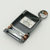
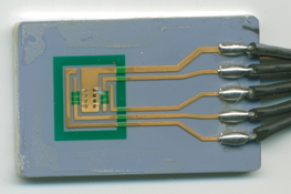
On the recapping front. I actually learned soldering, bought for 200 euros worth of magnifier, soldering stations, test PCB to train, the whole nine yards. I recapped in a very ugly way but hey, it works, the C42 capacitor. aaaaaaaand.... That made absolutely no difference

But I did it with a clean iteration of the scanner. Meaning the zigzag effect was very feint. So I took another ccd unit laying around that I knew was terrible. I made some test scans. Recapped it, and swapped the whole ccd unit into the working scanner. It still looked like utter shit. No difference at all.
My take is that it's a lot more complicated than I thought
, and out of my paygrade. But hey at least I can solder now.