Hiding in Plain Sight

about to extinct

D
about to extinct

  • 2
  • 0
  • 95
Fantasyland!

D
Fantasyland!

  • 9
  • 2
  • 132
perfect cirkel

D
perfect cirkel

  • 2
  • 1
  • 130

Recent Classifieds

Forum statistics

Threads
198,752
Messages
2,780,376
Members
99,697
Latest member
Fedia
Recent bookmarks
6

Chuck_P

Subscriber
Joined
Feb 2, 2004
Messages
2,369
Location
Kentucky
Format
4x5 Format
Like I said, flare and many other factors are incorporated into photography. Photographic scientists and engineers have worked hard in order to make photography work without having to understand it. As I've shown, flare is also incorporated into the Zone System, albeit unintentionally. For those wanting to discuss and understand the photographic process with all the factors that come into play within the process, they should be part of defining, analyzing, and explaining the process else there will be a gap in understanding how it works.

There's an easy way to extrapolate what is considered normal flare. Kodak considers a CI 0.58 for normal processing. The LER for the middle of a grade 2 paper range is 1.05. The average scene luminance range is 2.20 logs.

1.05 / 2.20 = 0.477

Take off a stop from the luminance range

1.05 / 1.90 = 0.553

Close but not exact. Take off another 1/3 stop.

1.05 / 1.80 = 0.583

So, Kodak considers the average flare to be 1 1/3 stops. Flare is part of their normal.

Flare helps make sense of the photographic process.

But what of the flare factor when enlarging? One stop? The image on the paper will be lower in contrast to some degree than the information on the negative, unless the negative is contact printed of course. If you assume a 1 stop flare factor, then an LER of 1.05 with consideration of one stop of enlarging flare, then a negative density range of 1.35 ( and higher CI) would help to offset losses from flare with enlargement, would it not?
 
OP
OP
Stephen Benskin
Joined
Jan 7, 2005
Messages
2,612
Location
Los Angeles
Format
4x5 Format
What if the lens is wide open and I'm using shutter speeds to control exposure? Wouldn't flare from a brightly lit white card be in play even though I'm exposing for low values?

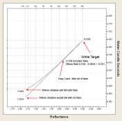
In the conditions you've outlined, veiling flare would have to double the highlight exposure to reproduce the effect of one stop of flare, and I don't think it's capable of that. Take a look at the camera image curve. The white card falls at the high end. A one stop flare factor doubles the shadow exposure. An exposure of 0.0032 mcs is added each point on the curve. By the time it gets up to the highlight, it doesn't add much to it value. I would like to point out that this example uses a camera image curve representing a 71/3 stop average luminance range. A white card would be just a small line or a dot.

In camera testing would meter the card and stop down. This just moves everything down.

Flare Curve.jpg

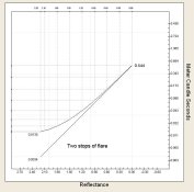
Just to help make a point, I doubled the amount of flare in the example below, and the highlight exposure almost hasn't changed.

Flare Curve - 2 stops flare.jpg

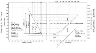
Here is the concept in a bigger context. The difference here is that it is based on testing using a middle gray card. It would be too messy to show the shift from a white card down to the shadow exposure.

2 Quad - Zone exposure test example.jpg
 
Last edited by a moderator:

Bill Burk

Subscriber
Joined
Feb 9, 2010
Messages
9,290
Format
4x5 Format
But what of the flare factor when enlarging? One stop? The image on the paper will be lower in contrast to some degree than the information on the negative, unless the negative is contact printed of course. If you assume a 1 stop flare factor, then an LER of 1.05 with consideration of one stop of enlarging flare, then a negative density range of 1.35 ( and higher CI) would help to offset losses from flare with enlargement, would it not?

You might be onto something there. But be careful, I wouldn't want you to overdevelop on account of some theory we haven't hashed out yet.

I use a filed negative carrier that exacerbates flare at the enlarger by letting additional white light spill around the edge.

And I have a negative that I call my "upper control limit" that has "important" densities that range 1.18 and when I print, it barely fits Grade 2. The neg has overall range 1.61 which includes spectral highlights, but I don't count that.

So I aim to keep my negatives no higher than 1.18 - not a far cry from 1.35 but still I want to go no higher.
 
OP
OP
Stephen Benskin
Joined
Jan 7, 2005
Messages
2,612
Location
Los Angeles
Format
4x5 Format
I'm kind of in the middle of something, but I want to throw this out there. It is Annex A: Relation between the paper range (R) and the effective density range of the negative from ANSI/ISO 6846 - 1983 for photography (sensitometry) black-and-white continuous-tone papers - determination of ISO speed and range for printing. The second paragraph should sound familiar, but it's the third paragraph that has much of the answer. The first, second, and forth give the reason why talking absolutes with the NDR / LER relationship is impossible.

"The log exposure range of a photographic paper provides a useful, but not a perfect, criterion for grading papers. It is useful because a satisfactory print is normally obtained when the log exposure range of a paper is matched to the effective density range of the negative image, provided that the scene and the scene lighting are normal. It is not a perfect criterion because papers with similar log exposure ranges will give prints that differ considerably in appearance if the shapes of the paper sensitometric curves are different. Moreover, a negative which prints well on a glossy paper (high Dmax) will print equally well on a matte paper coated with the same emulsion (low Dmax) even though their log exposure ranges will not be the same.

ISO range (R) which is determined directly from the log exposure range is, therefore, a useful guide for selecting a paper for a negative of known density scale. What is involved is the matching of the ISO range (R) with 100 times the effective density range of the negative image. For medium contrast papers, an exact match generally works best. For low contrast papers, the LER should be slightly less than the negative density range in most cases and conversely for high contrast papers. This means that to obtain the best prints from a single negative using two papers which differ in Dmax it is necessary in most cases for the lower Dmax, (lower contrast) paper to have a smaller LER.

When a negative is contact-printed, its effective density range image equals its diffuse density range as measured by a properly calibrated transmission densitometer (see ISO 5). When an enlarger is employed, the effective negative density range will be greater because of the scattering characteristic (Q-factor) of the negative film, (Stray light [flare] typically reduces the density scale by 5 to 10 %). A direct determination of the effective density range of the negative can be made with a photometer by measuring the maximum and minimum illuminance of the projected sharp image on the enlarger easel.

It must also be remembered that optimum print quality depends on aesthetic factors which may indicate the use of a paper whose log exposure range differs considerably from the density range of the negative. Thus, the use of the ISO range/negative density range relationship is only approximate, as a starting point for critical work. The paper range required should be determined for each printed/enlarger, developer, and paper surface combination."
 

Chuck_P

Subscriber
Joined
Feb 2, 2004
Messages
2,369
Location
Kentucky
Format
4x5 Format
You might be onto something there. But be careful, I wouldn't want you to overdevelop on account of some theory we haven't hashed out yet.

I already develop to a NDR of 1.2 and I'm certainly not overdeveloping. Using ZS vernacular, that's a range between a Zone VIII target density for "normal" development of 1.3 down to the EI threshhold of 0.1 at Zone I. IMO, I don't think it's useful to discuss a range on the negative that exceeds the upper limit of the textural range i.e., Zone VIII, perhaps to Zone IX, which I do not consider specular in nature...............or, a range that falls below the threshhold. Referencing Stephen's post #87, I consider the "minimum" illuminance to be the threshhold point at Zone I and the "maximum" illuminance to be, probably a Zone IX illuminance, but I currently have completed tests using Zone VIII as the important upper limit of the density range.
 

Bill Burk

Subscriber
Joined
Feb 9, 2010
Messages
9,290
Format
4x5 Format
I already develop to a NDR of 1.2 and I'm certainly not overdeveloping. Using ZS vernacular, that's a range between a Zone VIII target density for "normal" development of 1.3 down to the EI threshhold of 0.1 at Zone I.

Does this print on Grade 2 (or the equivalent filtration) for you or do you have to go to Grade 1? Anyway I just don't want you to change to 1.35 based on this discussion if you already found 1.2 works.

I was going to carry my tests through to the end and draw a chart of my 4-quadrant tone reproduction before deciding my desired target range. Then I found that real negative that "proved" what my target range should be, and short-circuited my plan to carry my tests to the conclusion.

After all, I had my answer.
 

Chuck_P

Subscriber
Joined
Feb 2, 2004
Messages
2,369
Location
Kentucky
Format
4x5 Format
Does this print on Grade 2 (or the equivalent filtration) for you or do you have to go to Grade 1? Anyway I just don't want you to change to 1.35 based on this discussion if you already found 1.2 works.

The short answer is, yes. I base that on just how easily I can produce a very satisfactory "straight print", no dodging or burning or other measures. In the way of an explanation, that is, a decided upon enlarging exposure time that fulfills my expectations (visualization if you will), both in the high value tonal area(s) of the print in the regions of Zone VII and VIII and the low value area where I made the particular shadow "placement". If I can achieve that, then I know I have something I can work toward within the confines of the information in the negative for the print I saw when the exposure was made. For me, I don't find any glory in making a satisfactory final print from a difficult and fussy negative, I find it annoying and who wants to be annoyed while in the darkroom :tongue:.

I realize that some of the wordage here is somewhat cliche', especially for anyone who is fluent with the ZS, but being cliche' in no way diminishes the method.
 
Last edited by a moderator:
OP
OP
Stephen Benskin
Joined
Jan 7, 2005
Messages
2,612
Location
Los Angeles
Format
4x5 Format
According to Annex A of the paper standard, enlarger flare reduced the apparent NDR by 5% to 10%. That translates to a density difference of 0.05 to 0.10. But that’s not all it said. “When an enlarger is employed, the effective negative density range will be greater because of the scattering characteristic (Q-factor) of the negative film.”

The reason why different density ranges are required to print on the same grade of paper using different types of enlarges comes from the scatting of light off the negative. This is called the Callier coefficient. The effect is greater the more specular the light source. Condenser enlargers have a higher Q-factor than diffusions. What this means is that the same negative printed in a condenser enlarger will have a higher effective negative density range than in a diffusion enlarger. That’s why there’s frequently a separate CI for a diffusion enlarger and a condenser enlarger.

The effective density range of a negative printed in a diffusion enlarger is about the same as if it were contacted. How is this possible when the enlarger has flare? Diffusion enlargers also have a Q-Factor although it is generally very small. In Richard Henry’s Controls in Black and White Photography, he found it to be 1.05. He found a condenser enlarger to have a Q-Factor of 1.26. Photographic Materials and Processes doesn’t have a value for diffusion, but has a condenser enlarger at 1.30. Both sources found similar figures with Henry’s being on the lower end. It’s then possible to predict the Q-factor for a diffusion enlarger would be slightly higher if Materials and Processes had thought to list it.

With a diffusion enlarger, the loss of effective negative density range due to flare appears to be generally negated by the effective increase in NDR from the Callier coefficient.

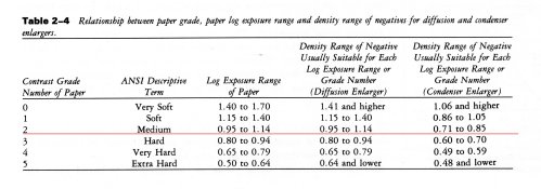
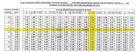
Let’s take a look at a chart with the aim negative density values for both diffusion and condenser enlargers.

LER and NDR chart.jpg

The chart makes a distinction between the paper LER and the aim NDR. As the diffusion negative density ranges are equal to the paper LER values, one would assume that the aim values take into consideration values for both average flare and an average Q-factor.
 
Last edited by a moderator:
OP
OP
Stephen Benskin
Joined
Jan 7, 2005
Messages
2,612
Location
Los Angeles
Format
4x5 Format
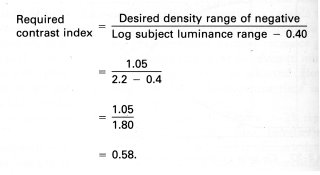
Another bit of information hiding in plane sight. The following equation can be found in Photographic Materials and Processes. It shows how to determine the proper contrast index to produce a desired negative density range in consideration of the subject's luminance range and camera flare.

CI Equation.jpg

The part that is hiding is this RIT text book's value for flare is in perfect agreement with what Kodak uses. Below is a developmental table used at Kodak.

Contrast Indexes - Kodak - Diffusion .jpg

I guess it shouldn't come as a surprise considering the close relationship of the two institutions.
 
Last edited by a moderator:

Chuck_P

Subscriber
Joined
Feb 2, 2004
Messages
2,369
Location
Kentucky
Format
4x5 Format
A direct determination of the effective density range of the negative can be made with a photometer by measuring the maximum and minimum illuminance of the projected sharp image on the enlarger easel.

I've only one way to measure the density range and that is with a densitometer. My effective range is between a specified low target density i.e., the Zone I threshhold and a specified desirable high target density i.e., that which defines my personal "normal" development time for the film and developer of choice (a density of 1.3 at Zone VIII). Let's talk about this absent of flare consideration, already know it some effect.

NDR is used a lot in these discussions, but I believe the way it is used and thought of is not consistent among us, perhaps it is and I'm just not seeing it. Do these discussions of the "maximum" illuminance include even the specular densities. If so, how useful can that possibly be outside of a laboratory, they will be paper base white no matter what when it comes to putting the image on the paper. Define "effective density range" as this quote means for others to understand it, just the skinny of it if you don't mind, I'm just curious.
 

Bill Burk

Subscriber
Joined
Feb 9, 2010
Messages
9,290
Format
4x5 Format
NDR is used a lot in these discussions, but I believe the way it is used and thought of is not consistent among us, perhaps it is and I'm just not seeing it. Do these discussions of the "maximum" illuminance include even the specular densities.

No, they don't include the specular densities. Say you contact print your test wedge. Your NDR would be related to the corresponding patches that gave you reflection density range in the print of (Todd/Zakia recommend 0.04 to 90% of paper dMax).

I see we discussed this about a year ago. Chuck, do you still aim for 1.1 to 1.2? Nothing much has changed for me in the past year, except my enlarging lens got dusty in that year and had to be cleaned again.

http://www.apug.org/forums/forum37/84994-critical-thinking-2-normal-negative-density-range-zs-vs-tone-reproduction.html
 

Chuck_P

Subscriber
Joined
Feb 2, 2004
Messages
2,369
Location
Kentucky
Format
4x5 Format
No, they don't include the specular densities. Say you contact print your test wedge. Your NDR would be related to the corresponding patches that gave you reflection density range in the print of (Todd/Zakia recommend 0.04 to 90% of paper dMax).

I see we discussed this about a year ago. Chuck, do you still aim for 1.1 to 1.2? Nothing much has changed for me in the past year, except my enlarging lens got dusty in that year and had to be cleaned again.

http://www.apug.org/forums/forum37/84994-critical-thinking-2-normal-negative-density-range-zs-vs-tone-reproduction.html

Yes, 1.2, like I described, but I can't read reflection densities, I determine my range directly from the negative.
 
OP
OP
Stephen Benskin
Joined
Jan 7, 2005
Messages
2,612
Location
Los Angeles
Format
4x5 Format
“A direct determination of the effective density range of the negative can be made with a photometer by measuring the maximum and minimum illuminance of the projected sharp image on the enlarger easel.”

This is an excerpt from the ANSI/ISO paper standard. They tend to use very precise language. In this context, effective density range isn’t referring to the actual density range of the negative but its equivalence at the paper plane.

Let’s say a 35mm negative is printed in a 4x5 negative carrier without any masking around the negative. What ever the density range of that negative, the excessive flare will reduce the density range the paper effectively sees.

A condenser enlarger has a Q-factor of 1.30. A negative with a density range of 1.05 will have an effective density range of 1.05 * 1.30 = 1.36 at the paper. Turning this around, what would the negative density range have to be for a negative printed with a condenser enlarger onto a grade 2 paper with an LER of 1.05?

Multiply the reciprocal of the Q-factor by the LER.

1 / 1.30 = 0.769
1.05 * 0.769 = 0.81

Compare it to the table in post #91.

The paper LER is chosen for the effective negative density range and not the actual negative density range. That is why there are different suggested negative density ranges for negatives printed on condenser and diffusion enlargers.

The concept is the same with the camera image. A scene might have a luminance range of 7 stops, but at the film plane, flare has reduced it to an effective 6 stop range. It is the effective range which is what’s important because it is what is actually used. In this example, the film would be developed for the 6 stop range and not seven.
 
Last edited by a moderator:

Chuck_P

Subscriber
Joined
Feb 2, 2004
Messages
2,369
Location
Kentucky
Format
4x5 Format
This is an excerpt from the ANSI/ISO paper standard. They tend to use very precise language. In this context, effective density range isn’t referring to the actual density range of the negative but its equivalence at the paper plane.

I can only determine the NDR from the actual negative. With VC paper, determining the amount of filtration that best suits the range I develop to is a simple enough thing to do.
 

Bill Burk

Subscriber
Joined
Feb 9, 2010
Messages
9,290
Format
4x5 Format
I can only determine the NDR from the actual negative. With VC paper, determining the amount of filtration that best suits the range I develop to is a simple enough thing to do.

If the ISO guys determine NDR at the base of the easel when rating paper, that doesn't mean you have to. Ansel Adams didn't use an analyzer at the easel so I won't tell you to.

It would include flare if you did. But by the time you get to the enlarger, you no longer have "only one shot to get it right." You don't have to set exposure based on estimates of subject luminance, or estimate camera flare based on your optics, the subject and the direction of the light. You don't have to figure out film development time to make it come out with an NDR that you want. You already did all the dangerous work.

Now with a good negative, even if there is flare at the enlarger, you have the luxury to try different times and contrasts until it works. Whether or not the range fits the paper, exceeds it or is shorter.
 

Chuck_P

Subscriber
Joined
Feb 2, 2004
Messages
2,369
Location
Kentucky
Format
4x5 Format
If the ISO guys determine NDR at the base of the easel when rating paper, that doesn't mean you have to. Ansel Adams didn't use an analyzer at the easel so I won't tell you to.

It would include flare if you did. But by the time you get to the enlarger, you no longer have "only one shot to get it right." You don't have to set exposure based on estimates of subject luminance, or estimate camera flare based on your optics, the subject and the direction of the light. You don't have to figure out film development time to make it come out with an NDR that you want. You already did all the dangerous work.

Now with a good negative, even if there is flare at the enlarger, you have the luxury to try different times and contrasts until it works. Whether or not the range fits the paper, exceeds it or is shorter.

I agree totally with all that you said. One thing is for sure, with a quality VC paper, the LER that suits your NDR is present and waiting, and all that is required to have fun in the darkroom is to make good and consistent negatives, which the ZS has taught me to make, on most occasions that is :D.
 
OP
OP
Stephen Benskin
Joined
Jan 7, 2005
Messages
2,612
Location
Los Angeles
Format
4x5 Format
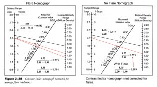
Here's another hidden example. Below are two contrast index nomographs. The film's contrast index can be derived by drawing a line from the scene luminance range to the desired negative density range. The nomograph on the left incorporates average flare and is from Photographic Materials and Processes. The one on the right is the same nomograph but it has been adjusted to eliminate the influence of flare.

Flare and no Flare Nomograph.jpg

In order for the statistically average scene of 2.20 to produce a negative density range of 1.05 under average flare conditions, the negative needs to be developed to a CI 0.58. Under the same flare conditions, a scene with a luminance range of 2.10 requires a CI of 0.725 to produce a negative density range of 1.25.

It's also possible to do the same thing mathematically by using the contrast index equation from post #92.

1.05 / 2.20 - 0.40 = 0.583
and
1.25 / 2.10 - 0.40 = 0.725

Let's compare these numbers with those derived from the no flare nomograph. A CI of 0.477 is required to produce a negative of 1.05 from a 2.20 luminance range scene. For a luminance range of 2.1, a CI of only 0.595 is needed to produce a negative density range of 1.25. The math looks like:

1.05 / 2.20 = 0.477
and
1.25 / 2.10 = 0.595

A contrast index of around 0.56 to 0.58 has long been considered "normal" processing. That eliminates the set with a CI of 0.725 and the set with a CI 0.477 as representing actual conditions.

The contrast index for the 1.05 negative under flare conditions is almost identical to the CI aim for the 1.25 negative under no flare conditions. Both fall around the classic normal CI value. As both indicate the negatives be processed to the same contrast index, the processing will be identical therefore the resulting negatives have to be identical for the same scene. But how can shooting a scene with the same luminance range and processing the negatives identically produce different density ranges as those two sets of numbers suggest? The simple answer is they can't.

Let’s also consider the relationship between the negative density ranges and the paper LERs. A negative density range of 1.05 falls in the center of the grade 2 LER paper range for printing on a diffusion enlarger. A negative with a density range of 1.25 falls near the middle of a grade 1. See the chart in post #91. That eliminates the set with a negative density range of 1.25. That leaves the 2.20 luminance range with flare, processed to a CI 0.58, producing a negative density range of 1.05 as best representing the conditions of use.

The only way all the established aim values fit together is through flare, and the answer is right there in the nomograph if you look for it.
 
Last edited by a moderator:

Chuck_P

Subscriber
Joined
Feb 2, 2004
Messages
2,369
Location
Kentucky
Format
4x5 Format
I know CI is important to these discussions that are highly technical in nature. But, a ZS practitioner (if he or she considers themselves strict about it) does not really consider CI or any other measurement of contrast that connects points on the curve with a straight line. It's the comparison of the entire curves of at least two films or one film with different developers that is considered most valuable. It's just a thought.
 
OP
OP
Stephen Benskin
Joined
Jan 7, 2005
Messages
2,612
Location
Los Angeles
Format
4x5 Format
Michael, we should put effort into something that's not a waste of time. Are there any specific wrinkles in your understanding of flare?
 
Last edited by a moderator:

Bill Burk

Subscriber
Joined
Feb 9, 2010
Messages
9,290
Format
4x5 Format
Michael,

How do you test for Zone XIV? I guess a camera test where you expose at f/11 for 1 second in daylight would about do it, but is that what you do?

So you've heard the argument that a flat-tone subject is flare free. And you want to estimate how much flare your camera/lens/subject causes?

I know it sounds simple but all I would do for a flare test is take a few regular pictures and make notes of the different meter readings in the subject*, making sure to pick a subject that can be clearly sketched and with different shadow areas and with a full subject range. If you have a coffee can painted black inside or a top-hat you can throw in, all the better.

Then after developing that negative, just cross-check all your meter readings with what you got.

I believe the difference is going to be due to flare. (If it isn't due to development times or exposure errors)

*It may help to walk right up to the subject and take really close up meter readings. The reading I get underneath a car is greatly different when I spotmeter from a distance, and when I walk right up to it. Maybe note both meter readings. It might turn out your spotmeter has same/similar flare as your camera making the spotmeter reading accurate at predicting what hits the film.
Seems to me any discrepancy between meter reading and actual result... would be flare.
 

Bill Burk

Subscriber
Joined
Feb 9, 2010
Messages
9,290
Format
4x5 Format
I know CI is important to these discussions that are highly technical in nature. But, a ZS practitioner (if he or she considers themselves strict about it) does not really consider CI or any other measurement of contrast that connects points on the curve with a straight line. It's the comparison of the entire curves of at least two films or one film with different developers that is considered most valuable. It's just a thought.

I agree curve families are extremely valuable.

But I believe ZS practitioners connect points on the curve with a straight line, and I like to think as an homage to ZS, the points used to determine CI were chosen in much the same way as ZS - by relating to actual paper...

To find Zone System N development time, you look for a curve that fits two points:

Point 1 X = Zone I
Point 1 Y = almost black on the print

Point 2 X = Zone VIII
Point 2 Y = almost white on the print

And then to solve for other development times you change Point 2 X, for example...

N+1 solve for Point 2 X = Zone VII
N-1 solve for Point 2 X = Zone IX

Applying Zone System development times for N, N+1, and N-1 is easy - develop for the times you wrote down.

To apply Contrast Index in the darkroom you have to solve "word problems" to find development times.
 

Chuck_P

Subscriber
Joined
Feb 2, 2004
Messages
2,369
Location
Kentucky
Format
4x5 Format
To apply Contrast Index in the darkroom you have to solve "word problems" to find development times.

I have to disagree with this one Bill. First, not saying anything is wrong with CI, only that within the context of the ZS (yes, I'm speaking as taught in The Negative), CI is not needed to find "N", "plus", or "minus" times. It certainly can be if one chooses to employ the ZS using CI, mean Gradient, whatever, to find their times, but as it is taught from the source, it is not. I've got development times for TMX with d-76 1:1 and hc-110 1:63 and 1:119, I did not use CI to determine them, they were determined as taught and they work quite well. My comment about ZS practitioners was poorly worded, there are many ZS practitioners, but it is evident that there are those who are quite fluent with it and those, well, I'll just leave it there.

With d-76 1:1, which is quite a straight-lined curve in my process, gamma can be easily determined, however, finding gamma, is not required to find development times.
 

Chuck_P

Subscriber
Joined
Feb 2, 2004
Messages
2,369
Location
Kentucky
Format
4x5 Format
It may help to walk right up to the subject and take really close up meter readings. The reading I get underneath a car is greatly different when I spotmeter from a distance, and when I walk right up to it. Maybe note both meter readings. It might turn out your spotmeter has same/similar flare as your camera making the spotmeter reading accurate at predicting what hits the film.
Seems to me any discrepancy between meter reading and actual result... would be flare.

Metering along the lens axis from the camera position, IMO, would be most representative.........the light has to travel that distance to the film. Therefore, the meter reading should also be from that distance, IMHO.

This is more directed at Michaels comments on his flare issues----my approach to it, not scientific, only practical:
If I am concerned about flare being a particular problem with an exposure, I make a small exposure adjustment to the meter reading by stopping down, usually just a 1/3 to 1/2 stop to try and keep my shadow placement as true as possible. I have 1/3 stop pencil marks evenly spaced between the aperture values on my lenses, in case one is wandering, works well for me so far. I simply cannot subscribe to the idea of there always being a 1 or 1 1/3 stop of flare present just because I have a lens on my camera..........flare is certainly a consideration, it is never a consistent thing, but I believe it has been my experience that the image contrast and subject contrast can, not always, be quite close (with quality multi-coated lenses), but is never perfectly matched either.

Flare is not a consideration when I carry out EI tesing either, I just try to compensate for it on a negative by negative basis, if at all.
 
Last edited by a moderator:

Bill Burk

Subscriber
Joined
Feb 9, 2010
Messages
9,290
Format
4x5 Format
I have to disagree with this one Bill. First, not saying anything is wrong with CI, only that within the context of the ZS (yes, I'm speaking as taught in The Negative), CI is not needed to find "N", "plus", or "minus" times. It certainly can be if one chooses to employ the ZS using CI, mean Gradient, whatever, to find their times, but as it is taught from the source, it is not. I've got development times for TMX with d-76 1:1 and hc-110 1:63 and 1:119, I did not use CI to determine them, they were determined as taught and they work quite well. My comment about ZS practitioners was poorly worded, there are many ZS practitioners, but it is evident that there are those who are quite fluent with it and those, well, I'll just leave it there.

With d-76 1:1, which is quite a straight-lined curve in my process, gamma can be easily determined, however, finding gamma, is not required to find development times.

I think you read me wrong because I think we are in agreement.

You are absolutely right, Zone System is self-contained and it gives you development times that you can use right away. To use ZS you don't need to know or be aware of CI (or similar Gamma which uses less practical points the paper can't use). The Zone System works, and I enjoy reading and writing about it in its purest form, its history, and the ideas that have followed. We live in a wonderful time when we can go back in time and use historic ideas, that still work.

Contrast Index is part of a different system, the two different systems use different vocabularies and procedure steps but seek a similar goal using similar information... to find film development time given shooting conditions. To use CI, you don't need to know ZS.

After you find your times, you don't have to do any more math... but I have to do "word problems".

Word problems like my kids get in math...

Bill took a picture in bright sun and spotmetered a shadow and placed it on Zone II. He spotmetered an important highlight and found it was falling at Zone VII, so he made a note to develop N+1. He uses NDR 1.00 as a target to fit his paper. What is the development time in D-76 1:1?

Bill has a lot of math to do before he gets his answer:
1. N+1 implies Zone I through Zone VII, subject brightness range 6 stops.
2. 6 x 0.3 = 1.8
3. Subtract 0.4 for flare
4. 1.00 divided by 1.4 = 0.71
5. From previously-prepared lookup chart for Time/CI for TMY2 in D-76 1:1, 0.71 = 15 minutes

Chuck took a similar picture, and also made a note to develop N+1. He uses NDR 1.20 as a target to fit his paper. What is his development time in D-76 1:1?

Chuck gets his answer at a glance:
1. Look at N+1 on chart and develop for that time. Maybe 18 minutes?

Why do we get different times? Because we use different paper. What happens if Chuck wants to use Bill's paper? Chuck has some testing to do but he knows the steps and it's fun to do. What happens if Bill wants to use Chuck's paper? He plugs the number 1.20 in step 4.
 
Photrio.com contains affiliate links to products. We may receive a commission for purchases made through these links.
To read our full affiliate disclosure statement please click Here.

PHOTRIO PARTNERS EQUALLY FUNDING OUR COMMUNITY:


Ilford ADOX Freestyle Photographic Stearman Press Weldon Color Lab Blue Moon Camera & Machine
Top Bottom