LIK
Member
There are clearly no problems with lighting. I have both the seals and the frame installed. I'll see what the problem is. Thanks


 )
)Hi.
first "twolaser" version.
Question. I searched in the whole thread - But i dont found an answer why
i have in the second row a "Err" for both lasers/sensor. I made a senn test, "blocked" is
flashing with seen, but worked in ambient light slightly. i changed sensor, but the same.
i cant change the nano board, because new auth. code is necassary.
any idea?
many thanks
Hi!
Finally managed to finish this project. Not the perfect one (somehow I switched sensors\lasers placement), but I like it. A huge thank you to Niglyn and everyone who posted their builds, it helped a lot in the process! And I think it works perfect! No strange readings or anything like that. I've tested two of my cameras already and the results look plausible.
I have a problem with my laser receiver..
I checked all my receiver boards (7 pcs.), all the same.
in darkness roundabout 2,2V, with laser in middle 0V.
The avr differece betwen high/low is between 2V - 3V.
It seems, that the BS12B20 board is for the temperature sensor.
what is the name of the phototransistor?
thx
...
Der Sensor selbst ist ein ISO203, wie unten gezeigt. Er enthält eine optische Linse, einen Spannungsregler, einen Lichtsensor, einen Verstärker und einen Schaltausgang.
Dadurch wird ihre Verwendung ganz einfach, ohne dass zusätzliche Schaltkreise erforderlich sind.
View attachment 397275
Problem solved > curios.
The receiver boards i bought from amaz are all 10 the same.
But! it seems that the high-density converter have changed.
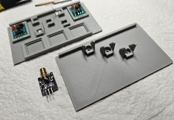
No ISO203 , its a TSL257.
View attachment 397276
I changed to the pinout like the datasheet and it works.. pin 2 and 3 overcross.
View attachment 397277
in dark 0V.
with laser 3,5v oder more.
thx, Andreas

By forum rules my permissions are restricted at the moment.


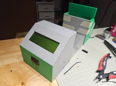
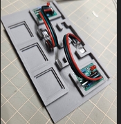
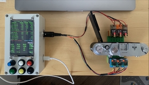
As I promised, some pictures of my build.
I went with the recommended standard but I'm not a big fan of cables coming out on the side so I relocated the connectors to the top. 3 pin for the lasers, 5 pin for the sensors. Still have enough space to install the USB-C port that should arrive next Monday.
I made the cables today, so after the sensors arrive I'll do some measurement and try to 3D print something nice. Hopefully some test results are coming next week.
View attachment 397784View attachment 397785
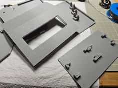
Hi, thanks for posting the photos of your build.
The screen cut-out looks very neat, how did you do this?
(I used to have a milling machine, which was ideal for making the panel cut-outs)
I notice you are using slightly different buttons, with chrome bezels.
They look to be slightly smaller, which can help, as there is only just enough space for the specified buttons.
You could use the 5-pin din for both sensors & Lasers. This way you only have one cable going to the sensor frame.
Hope your USB cable and sensors arrive soon.

 www.photrio.com
 since I started my apprenticeship in the Measurement and Control department of a large German chemical plant - and I did not have much serious practice in the meantime (migrated to the upcoming IT industry after several years).
Ok, several parts are still missing. But I've noticed that I made a mistake: I ordered the TFT display without the touch functionality.
Will this cause issues when using the tester?
Firmware Update - ESP32 imminent
Hi guys, after Simplex mentioned touch, I thought I might as well add it, having an hour spare.
Touching the screen anywhere works as an alternative to pressing the black button to return.
Works on splash screen and legend screen.
For the alignment/set-up screen, touch at the bottom.
- hope to add touch to the setup functions as well.
Other improvements,
New simple display, so the user now has the choice of three display options.
The latest display auto-ranges the milliseconds and seconds display.
(Pressing blue cycles through the different screens)
To save the selected screen as default, enter the alignment/set-up screen & exit.
Layout slightly altered in the detailed screen, including moving curtain speeds up, with 'nearest' & nearest deviation below.
Deviation fractions are now displayed without a leading zero.
GitHub already has a new wiring PDF, showing the additional wiring for touch functionality (four additional wires)
for those wanting to get the wiring done now, before the firmware arrives.
There is also a hidden touch functionality test.
When booting & the small test is on the screen, press and hold the black button.
Nothing will be displayed on the tft, but touching it will show the x, y, z coordinates output to the pc screen.
| Photrio.com contains affiliate links to products. We may receive a commission for purchases made through these links. To read our full affiliate disclosure statement please click Here. |
PHOTRIO PARTNERS EQUALLY FUNDING OUR COMMUNITY:  |