Printalyzer - Darkroom enlarging timer & exposure meter

Brentwood Kebab!

A
Brentwood Kebab!

  • 0
  • 0
  • 9
Summer Lady

A
Summer Lady

  • 0
  • 0
  • 9
DINO Acting Up !

A
DINO Acting Up !

  • 0
  • 0
  • 8
What Have They Seen?

A
What Have They Seen?

  • 0
  • 0
  • 13
Lady With Attitude !

A
Lady With Attitude !

  • 0
  • 0
  • 13

Recent Classifieds

Forum statistics

Threads
198,755
Messages
2,780,468
Members
99,698
Latest member
Fedia
Recent bookmarks
0
OP
OP
dkonigs

dkonigs

Subscriber
Joined
Sep 17, 2009
Messages
358
Location
Mountain View, CA
Format
Multi Format
Out of curiosity, what kind of display did you select? I searched Mouser a few weeks ago, and all the sophisticated displays cost too much for this accessory. The cheapest displays I saw were for clocks, but they are probably too restrictive.
Yeah, buying any display from a place like Mouser or Digi-Key is way too expensive for this project to be viable. That's why I was originally trying to avoid one. Then, I found out about BuyDisplay.com where you can actually get displays much more cheaply.

This is the one I'm currently using:
https://www.buydisplay.com/white-1-3-inch-oled-i2c-arduino-ssd1306-display-module-connector-fpc

(I was initially tempted to go even smaller/cheaper, but I was worried that a smaller display would become overwhelmed by the buttons and might be too tiny for comfort.)
 

sasah zib

Member
Joined
Jul 31, 2021
Messages
192
Location
St Regis
Format
Hybrid
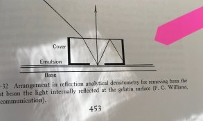
a fast thread scroll says you've probably covered this about reflection densitometers:
IMG_8948.jpeg
from Evans &
 

albada

Subscriber
Joined
Apr 10, 2008
Messages
2,172
Location
Escondido, C
Format
35mm RF
Now that you're done with the densitometer, it's time to work on the Printalyzer. The densitometer was your warm-up. 🙂
The following is a useful feature to put in the Printalyzer. Perhaps you've already thought of this, but if not, here goes:

After a test strip is printed, number the steps 1,2,3.... Let the user tell the Printalyzer, "On step 3, an element in zone 7 shall print as zone 6. On step 2, an element in zone 2 shall print as zone 3." The Printalyzer can compute exposure and grade based on these two points. If only one point is specified, then exposure alone can be set. The user can easily determine zones because you can put zone-numbers on the grayscale above the display, allowing the user to determine zones by putting the strip by the grayscale and matching shades. Actually, you don't need zone numbers. Instead, with the rotary encoder, you can have the user move a dot under the grayscale to the matching shade, and then to the desired print-shade. Another advantage of this idea is that exposure strips can have larger steps and thus cover a wider exposure range. Below, you'll see why this is an advantage.

I implemented this feature in my LED controller, using the easel meter made by DarkroomAutomation.com and a separately-printed grayscale, which Ralph Lambrecht calls a "zone ruler". The benefit of this idea is that only one strip needs to be printed to determine both exposure and grade.

In fact, if the strip covers enough exposure-range, times for dodges/burns can be determined. For example, for burning sky, the user could tell the Printalyzer, "Tell me the dodge/burn time to put zone 9 on step 4, on zone 8 in the print." The Printalyzer would reply, "Burn for 7 seconds." Thus, one strip can determine grade, exposure-time, dodge-time, and burn-time.

As you might have guessed, I brainstormed ways of extracting all information possible from a test strip in a manner that people would find easy to use. By implementing such features, you will not be making a clone of the RH Designs product; you will be making a product superior to it.
 
OP
OP
dkonigs

dkonigs

Subscriber
Joined
Sep 17, 2009
Messages
358
Location
Mountain View, CA
Format
Multi Format
As you might have guessed, I brainstormed ways of extracting all information possible from a test strip in a manner that people would find easy to use. By implementing such features, you will not be making a clone of the RH Designs product; you will be making a product superior to it.
Thinking about this idea a bit, there may actually be a few different ways to achieve the same goal. That goal being to first make a base exposure onto a test strip, then use modifications to that strip as a basis for tweaking the exposure and creating dodge/burn adjustments.

Another approach that I think might work better is that rather than seeing the test strip as the "input unit/type", see the test strip as more of an output visualization. The thing is actual adjustments to contrast grade are usually in discrete steps, even if time adjustments are more granular.

So here's another take on it:
After making a test strip, bring up a screen that shows a diagram of that strip with numbers in each box. Those numbers start at zero, and show a stop/zone offset from base. Every time you change the time or contrast, it updates these numbers to display how the darkness of each patch would change as a result of that adjustment.

Regardless, any of these ideas require mocking up diagrams of the user interface, thinking through how it would work, deciding on how best to integrate it with the buttons available, etc.

In any case, one of the biggest overall goals of the project is actually not to make a fixed-in-stone device. Rather to make something flexible, where the same hardware can be used to try out all of these ideas and improve on them via software updates.
 
OP
OP
dkonigs

dkonigs

Subscriber
Joined
Sep 17, 2009
Messages
358
Location
Mountain View, CA
Format
Multi Format
While I'm here, I might as well provide an update on what challenges lay ahead in terms of getting this project moving again. Better to do this in a separate comment.

First and foremost, the global semiconductor shortage affects this project far more than the densitometer. That being said, its been a while since I last attempted to check order-ability of the current bill-of-materials. (But it may make it difficult to build more than prototypes for a while, and could even make prototypes difficult to procure parts for.)

Second, before this can turn into a real product, I need to figure out how to manage the whole "safety certification" minefield. Both in terms of what red tape I actually need to pass, and who can help me make sure I'm good in that department. Because the timer switches mains AC voltage, and keeping it usable for the primary end-user makes this a requirement, this is an unavoidable problem.

Now as far as actual design considerations, there are a few areas where I need to revisit and consider what changes to make:
  1. Do I include a separate interface for controlling LED enlargers, often of the DIY type? For doing this, I'm considering using DMX512 due to its standard nature. There are off-the-shelf LED driver boards that can speak it, and I could always make simple adapter bricks if people need to connect to something else. Of course once I go down this route, figuring out how to integrate RGB control into the UI becomes another challenge, but one that could be dealt with later.
  2. What sensor should I use for the light metering probe? The one used in the current prototype is discontinued, and there are plenty of choices for alternatives. (The meter probe is actually designed to be an accessory that can be change in the future, perhaps even with multiple choices, so this specific decision doesn't need to be permanent.)
  3. Should I change the interface used to connect the meter probe? (The current one uses I2C over a mini-DIN connector. It works, but isn't hot-pluggable. I could attempt to fix that problem in the electronics, or switch to something else.) One design criteria I had for this was that I explicitly didn't want to put a microcontroller inside the meter probe, to avoid the need for updating firmware on the meter probe. That rules out fancier things like USB. I do still want the connection to the meter probe itself to be digital, so its easier to use modern sensors and so that I don't need to put any sensor-specific circuitry inside the main device.
There are also a couple of other to-do items floating out there, like redesigning the enclosure to something cheaper to mass-produce. Also, assembly of complete devices is likely to be fairly labor-intensive, since some parts of circuit board assembly that might be difficult to automate. But this will be a higher cost device than the densitometer, so considerations are a bit different.
 

albada

Subscriber
Joined
Apr 10, 2008
Messages
2,172
Location
Escondido, C
Format
35mm RF
  1. Do I include a separate interface for controlling LED enlargers, often of the DIY type? For doing this, I'm considering using DMX512 due to its standard nature. There are off-the-shelf LED driver boards that can speak it, and I could always make simple adapter bricks if people need to connect to something else. Of course once I go down this route, figuring out how to integrate RGB control into the UI becomes another challenge, but one that could be dealt with later.
LEDs enable some appealing features, so I encourage you to provide LED-support.

Electronic interface:
I think DMX512 is not suitable because it provides only 8-bit resolution for dimming, and @koraks and I independently discovered that a minimum of 12 bits is needed for sufficient resolution at low PWM-levels. I suggest using RS-232 with 0v/5v or 0v/3.3v voltage levels, via the standard D-sub connector. All microcontrollers support RS-232, and it's trivial to support in software. I suggest sending space-separated ASCII-hex numbers terminated by carriage-return so that a terminal program can monitor what's being sent across.

Features that LEDs can provide:
  • Allow the user to turn on the red LEDs to position a burn/dodge tool, and start exposure by tapping the foot-pedal. This feature is very handy.
  • The lens can be left at a sharp aperture because exposure can be changed via LED-brightness (as well as time).
  • No filters are needed because contrast is determined by green-blue ratio.
The challenge is to gracefully integrate these features into the existing UI which is designed for simple on/off-style lamps and contrast-filters.

Calibrations needed by LEDs:
  • PWM does not quite agree with brightness, and the deviation depends on the electronics, so a calibration (fills a LUT) is needed for this. If you don't want to deal with this, you could require that the LED-driver modify PWM as needed to make brightness linear.
  • For each paper, your controller needs to know the contrast-levels (grades, exposure ranges) that a set of green-blue ratios yield. I use six ratios ranging from nearly green-only to blue-only, and my controller interpolates between them. The simplest calibration method I can think of that would use your existing paper-tables is to have the user (1) make reference prints at all contrasts using white light and filters, (2) make prints using a set of ratios, adjusting power-levels to match the reference prints, and (3) enter the resulting green-blue PWMs (or log2 of them) into your controller.
 
OP
OP
dkonigs

dkonigs

Subscriber
Joined
Sep 17, 2009
Messages
358
Location
Mountain View, CA
Format
Multi Format
I think DMX512 is not suitable because it provides only 8-bit resolution for dimming, and @koraks and I independently discovered that a minimum of 12 bits is needed for sufficient resolution at low PWM-levels. I suggest using RS-232 with 0v/5v or 0v/3.3v voltage levels, via the standard D-sub connector. All microcontrollers support RS-232, and it's trivial to support in software. I suggest sending space-separated ASCII-hex numbers terminated by carriage-return so that a terminal program can monitor what's being sent across.
So I did some digging, and apparently others in the DMX world have also realized that 8-bit resolution isn't always enough. As such, its actually not that unusual for DMX512 devices to merge two adjacent channels to provide 16-bit control. I've found various dimmers out there that already support this.

The real problem is that there is no agreed-upon standard for controlling LED enlargers. The commercial products tend to bundle their own timers and be inaccessible to external control, and DIY projects use whatever the creator felt like at the time. Being able to stick with a standard like DMX512, even if nobody in this particular community is using it directly, does offer a couple of advantages:
  • Its a fairly robust system, with existing connector standards
  • There are existing products capable of understanding it, and doing things with its signal
  • It supports multiple devices, so it could be used to control both an enlarger and the safelights if desired. (though I'll still need to provide relay-switched AC outlets for both to cover the average case)
  • It would be relatively easy to come up with some reference designs, and maybe even reference/subassembly hardware, for people who want to interface with it
Of course I still haven't directly tinkered with it, but building some subassembly-level prototypes is on my to-do list for when I get this project rolling again.
 

garyj12

Member
Joined
Nov 12, 2022
Messages
1
Location
Harpenden, England
Format
Multi Format
So I did some digging, and apparently others in the DMX world have also realized that 8-bit resolution isn't always enough. As such, its actually not that unusual for DMX512 devices to merge two adjacent channels to provide 16-bit control. I've found various dimmers out there that already support this.

The real problem is that there is no agreed-upon standard for controlling LED enlargers. The commercial products tend to bundle their own timers and be inaccessible to external control, and DIY projects use whatever the creator felt like at the time. Being able to stick with a standard like DMX512, even if nobody in this particular community is using it directly, does offer a couple of advantages:
  • Its a fairly robust system, with existing connector standards
  • There are existing products capable of understanding it, and doing things with its signal
  • It supports multiple devices, so it could be used to control both an enlarger and the safelights if desired. (though I'll still need to provide relay-switched AC outlets for both to cover the average case)
  • It would be relatively easy to come up with some reference designs, and maybe even reference/subassembly hardware, for people who want to interface with it
Of course I still haven't directly tinkered with it, but building some subassembly-level prototypes is on my to-do list for when I get this project rolling again.

I hope you don't mind me interjecting here. I'm a recent proud owner, from across the pond, of the printalyser densitometer. I currently have an enlarger with a LED bulb and I'm currently using the densitometer to perform a calibration of my RH Designs Zonemaster light meter connected to my RH Designs stop clock pro. I'm really interested in the development of the Dektronics enlarging timer and exposure meter and noticed previous reference in this thread to the hard baked 'spooky numbers' used by RH designs. I recently managed to find a calibration procedure on the RH Designs website that seems to reveal these 'spooky numbers' referred to as 'Meter software constants'

The link to the full calibration procedure document is here: https://rhdesigns.co.uk/wp-content/uploads/2020/03/pluscal.pdf (also attached)

1668250827978.png


I've just finished my calibration using the densitometer procedure given in the latter half of the calibration document using the meter software constants and calculation table. Not yet tested in the darkroom with real prints, but results look in the right ball park compared to previous calibrations.

Apologies if forum members are already aware of this document, it is undated but still available on RH Designs website. Hopefully it will be of interest.
 

Attachments

  • pluscal.pdf
    31.1 KB · Views: 130

koraks

Moderator
Moderator
Joined
Nov 29, 2018
Messages
22,726
Location
Europe
Format
Multi Format
@garyj12 welcome to Photrio and many thanks for this useful addition! I'm sure that even if it's been posted before, it's still good to have it on hand in a place where it certainly is relevant.

@dkonigs @albada
RE: the protocol issue - it's a tough one, I think. I agree with @albada that an 8-bit limitation would not be ideal, although for B&W work it might be adequate. If this product is going to move into the color domain, then an 8-bit limitation would be a deal-breaker in virtually all instances. I have never looked into the DMX protocols, so I can't comment on how wise it is to rely on a workaround to make 16 bits by combining several channels and neither am I aware of the market for DMX512-capable modules and the extent to which they accommodate this 16-bit expansion.
I do see the value in trying to build on top of an existing protocol and DMX512 sounds like a more straightforward choice than Serial/RS232 (c.s.) because it would bring the interface within reach of those who don't want to do their own microcontroller programming.
One could even consider adding a three-channel PWM output, since virtually all dimming systems will use PWM one way or another, so it's pretty universal. The downside is that you'd have to make choices like PWM frequency and other low-level choices that depend to a large extent on the light source hardware.

The short of it is that there's probably no best solution out there. Maybe it's feasible to have two or three options to choose from, although this would evidently complicate hardware design.

The alternative, of course, is to grasp this opportunity to define a standard. Although of course, enforcing a standard upon a market is always tricky, and even more so if it's a one-man operation trying to set a standard in a landscape of DIY-ers, who will all have minds of their own.
 

albada

Subscriber
Joined
Apr 10, 2008
Messages
2,172
Location
Escondido, C
Format
35mm RF
One could even consider adding a three-channel PWM output, since virtually all dimming systems will use PWM one way or another, so it's pretty universal. The downside is that you'd have to make choices like PWM frequency and other low-level choices that depend to a large extent on the light source hardware.

PWM output has some compelling advantages:
  • All systems today can handle 5 volt PWM-input, either directly or via a resistor-divider in the lamp.
  • Lamp-electronics becomes very simple: a power supply and three drivers connected to the LEDs. No microcontroller.
  • Offering choices of three frequencies around 100/250/500 Hz should satisfy all drivers.
  • VGA D-sub connectors and cables can be used, as they contain RGB lines.
@koraks, that's a good idea.
 
Last edited:
  • albada
  • Deleted
  • Reason: Accidental reply.
OP
OP
dkonigs

dkonigs

Subscriber
Joined
Sep 17, 2009
Messages
358
Location
Mountain View, CA
Format
Multi Format
I'd just like to let you know, that even if I do choose to do something "fancy" like DMX512 (which is basically just RS-485 with some structure to the data), probably one of the first "adapter boards" I make will be something that connects to that interface on one side, and spits out a bunch of PWM signals on the other side.
 

albada

Subscriber
Joined
Apr 10, 2008
Messages
2,172
Location
Escondido, C
Format
35mm RF
Derek, I posted a description of all the novel features in my controller. You might get some ideas there. I posted that to prevent anybody from patenting any of those ideas, as none of us wants to be blocked by a patent.
Mark
 

albada

Subscriber
Joined
Apr 10, 2008
Messages
2,172
Location
Escondido, C
Format
35mm RF
Here's a suggestion based on experience.

My first controller imitated yours, and its rotary encoder (the "knob") was in the same place: to the right of the display. But I found that location was annoying to use because (1) it required a bit of reaching, (2) like most people, I'm right handed, so I would prefer to push buttons with my right hand, and (3) it causes the right hand to nearly or partly cover a couple of buttons, making pushing them with the left hand clumsier.

So in my second controller (1st photo in my thread about it here), I moved the knob to be near the lower-left where it was convenient to operate with my left hand while pushing buttons with my right hand.

You have a cluster of 4 buttons, two of which change time and two change grade. You can reduce that to two buttons, where one selects grade (changed with knob) and the other selects time (changed with knob). That will free enough horizontal space on the top panel to put your knob at the lower left, making two-handed operation convenient. If that's too large a change, you could just move the knob to the left side of the display to make it easier for right-handed folks to use.

Mark
 

koraks

Moderator
Moderator
Joined
Nov 29, 2018
Messages
22,726
Location
Europe
Format
Multi Format
making two-handed operation convenient

But making single-handed operations virtually impossible, right? I would see that as an issue since there will be quite a few people who will be put off by a UI that's dual-handed only. And not just the few unfortunate ones who can only use one hand - even though you really should keep them in mind as well!!
 

albada

Subscriber
Joined
Apr 10, 2008
Messages
2,172
Location
Escondido, C
Format
35mm RF
But making single-handed operations virtually impossible, right? I would see that as an issue since there will be quite a few people who will be put off by a UI that's dual-handed only. And not just the few unfortunate ones who can only use one hand - even though you really should keep them in mind as well!!

"Impossible." "Dual-handed only." Strong words there. C'mon, I'm only trying to improve the appeal and ease-of-use of the product based on actual experience.
The device could be used with one hand by moving the hand back and forth between knob and buttons, the same as with your present UI.
 
Last edited:

koraks

Moderator
Moderator
Joined
Nov 29, 2018
Messages
22,726
Location
Europe
Format
Multi Format
The device could be used with one hand by moving the hand back and forth between knob and buttons, the same as with your present UI.

That's an important addition; I thought you proposed a concept where you had to depress a rotary encoder button while pressing other buttons - i.e. true dual-handed operation. I would advocate against such an approach for reasons of accessibility.

As to the location of a knob/dial: as a right-handed person, I like to keep them positioned to the right-side of a display because otherwise the hand overlaps the display. It seems that you made an argument for the opposite, which I found a bit hard to follow. Of course, any optimization for right-handed people will be a minor hurdle imposed on the left-handed. Keeping a display on top and any input elements below it, generally works for anyone, however.
 
OP
OP
dkonigs

dkonigs

Subscriber
Joined
Sep 17, 2009
Messages
358
Location
Mountain View, CA
Format
Multi Format
I should probably point out that nothing about my current interface requires two hands to operate, and nothing requires pressing a button and operating the knob at the same time.

I mainly use the knob as an independent (mostly optional) control for fine-tuning things, or for more easily/quickly adjusting a number by a larger amount. I really just added it because everyone else has one, not because its absolutely necessary. However, because its there, I'll no doubt find more uses for it.
 

albada

Subscriber
Joined
Apr 10, 2008
Messages
2,172
Location
Escondido, C
Format
35mm RF
I should probably point out that nothing about my current interface requires two hands to operate, and nothing requires pressing a button and operating the knob at the same time.

I agree with that. My poor wording gave the wrong impression of requiring two hands. On my controller, two-handed is optional. Placing the knob around the lower-left makes two-handed more convenient. With Derek's present layout, a left-handed person's hand would cover the display while turning the knob. Moving the knob down would solve that problem.

In fact, the Printalyzer could have *two* knobs marked "Time" and "Grade", eliminating the four buttons that set them. To set numeric items, people prefer knobs over buttons. Minolta learned that in the 1990s when they came out with sleek-looking cameras with no knobs. But one had to push a button several times to set shutterspeed. The knob came back.
 
OP
OP
dkonigs

dkonigs

Subscriber
Joined
Sep 17, 2009
Messages
358
Location
Mountain View, CA
Format
Multi Format
Its time I share another project update here. I've been putting a lot of work into this project again lately, and I might as well share where things stand.

First, here's a little video I published a few weeks ago where I cover a lot of my work in progress:

The first half of the video is about densitometer projects. Skip ahead to around 13:00 where I'll start talking about the enlarging timer project.

Of course if you don't feel like sitting through that (and I don't blame you if you don't), here's a quick recap of where things actually stand as of today:
  • I've decided to split the device internals into two circuit boards. One handles all of the AC power input and rear ports, while the other is the main circuit board that does everything else. The reason is to keep the AC circuitry at arms length, and make it easier to isolate and nitpick its design.
  • I have added an XLR jack on the back for DMX512, which I plan to use as my "expansion connector" for everyone's DIY enlarger projects.
  • The new enclosure design is coming along nicely, and almost ready to get built
  • The updated designs for the main board and power board are also almost ready to build, pending a final round of review and nitpicking.
  • I've made major revisions to the power circuitry, and to the meter probe interface, with a focus on robustness and flexibility.
  • The meter probe itself is still a work-in-progress (more below)
Here are some pretty renders:
Screenshot 2023-05-10 163447.jpg


Screenshot 2023-05-10 163558.jpg


Okay, so about that meter probe...

The biggest to-do item there is that I need to select a new light sensor. The sensor I previously used has been discontinued by the manufacturer, and thus is not a good choice moving forward.

The main thing I need to nail down, is what this sensor actually needs to be capable of. The first prototype used an RGB sensor that let me do two things decently well: Take lux readings, and calculate the color temperature of the light source. The former was useful, while the latter felt more like a gimmick. Unfortunately it didn't have enough color sensitivity to be usable as a color analyzer.

For starters, I probably still want to be able to take lux measurements. Its a useful baseline to do everything else off of, mostly since paper specs are written in terms of lux.

What I don't know, is if there's any real use to color measurements or other areas of the spectrum, and whether or not its worth trying to do anything with them at this point.

I probably also need to adjust the dimensions of the PCB and re-model the shell in CAD, but those are mostly straightforward things that are unlikely to lead to major changes in appearance.

FYI, the intent is that I'll be able to make more than one version of the meter probe in the future. So the first model doesn't really need to do everything. Future models could add features, or I could even have more than one version of the meter probe with different sensors if it would be helpful.
 

albada

Subscriber
Joined
Apr 10, 2008
Messages
2,172
Location
Escondido, C
Format
35mm RF
Here's a yes/no question: Do you plan to transmit green-blue brightness-values out the XLR connector? Doing so would eliminate the need for contrast filters, a great convenience. If "no", then I see no need for the XLR connector, because you'll be transmitting only on/off commands to the enlarger. In that case, a DIY lamp could use your "enlarger" mains-output as the on/off signal. If "yes", then firmware will need a facility to enter the green-blue values for the contrasts. Or these could be included in the paper-calibration tables.
 
OP
OP
dkonigs

dkonigs

Subscriber
Joined
Sep 17, 2009
Messages
358
Location
Mountain View, CA
Format
Multi Format
Here's a yes/no question: Do you plan to transmit green-blue brightness-values out the XLR connector? Doing so would eliminate the need for contrast filters, a great convenience. If "no", then I see no need for the XLR connector, because you'll be transmitting only on/off commands to the enlarger. In that case, a DIY lamp could use your "enlarger" mains-output as the on/off signal. If "yes", then firmware will need a facility to enter the green-blue values for the contrasts. Or these could be included in the paper-calibration tables.

Yes, if you configure it to do that. The whole point of the connector is to have the flexibility to do those kinds of things, and to basically handle any form of enlarger (or safelight) control that's more complex than a mains-level on/off switch.

I'm not yet sure how I'll handle the configuration for the interface, but I'll need to come up with something flexible enough to handle many possible use cases.
 

koraks

Moderator
Moderator
Joined
Nov 29, 2018
Messages
22,726
Location
Europe
Format
Multi Format
What I don't know, is if there's any real use to color measurements or other areas of the spectrum, and whether or not its worth trying to do anything with them at this point.

Well, a color analyzer comes to mind. However, given the tiny size of that market and the effort it takes to get it right, I wouldn't put it too high up on the priority list.

The rationale behind a re-engineered color analyzer would be that the old Colorstar ones (touted as 'the very best' by some) can't handle PWM-ed light sources. The kind of sensors you use are inherently suitable for this, since they are light integrators. The Colorstar models relied on linear amplification of a photodiode signal, so the readings become erratic (haywire, is a better term) when you try to read a PWM-ed light source.

The reason is to keep the AC circuitry at arms length, and make it easier to isolate and nitpick its design.

And you can re-use the AC module for other projects :smile:

Great work, I'm enjoying the progress!
 
OP
OP
dkonigs

dkonigs

Subscriber
Joined
Sep 17, 2009
Messages
358
Location
Mountain View, CA
Format
Multi Format
Well, a color analyzer comes to mind. However, given the tiny size of that market and the effort it takes to get it right, I wouldn't put it too high up on the priority list.
Agreed on that. However, if I can find a sensor with enough color sensitivity to distinguish the tick-marks on my dichroic color enlarger head, I can think of another potential use case.
The ability to measure the effect of different contrast filters on the light source, and then the ability to figure out what color enlarger settings correspond to those filters.
For the more common dichroic color enlarger heads, there are published charts for this that are likely good enough. But I can think of a few other cases where it could be useful:
  • Fine tuning those charts for more granularity and filter variation
  • Building a chart for enlargers you don't have such a chart for (such as any LED heads), which could even be designed as an automated process.
Just some thoughts. Probably need to test some sensors before deciding on building in that kind of capability.

Another thing I'm wondering (mostly as a side-effect of other sensor research) is whether there's any point in measuring UV-A light under the enlarger. For normal B&W paper, I don't think its a terribly useful range, but I could be wrong. And there might be other materials people print on (I don't know) where it could be useful.
 
OP
OP
dkonigs

dkonigs

Subscriber
Joined
Sep 17, 2009
Messages
358
Location
Mountain View, CA
Format
Multi Format
So I've begun to go down the rabbit hole of sensor evaluation and testing, and have a few thoughts worth sharing. As I see it, the sensor in the meter probe should/could have the following requirements:
  1. Be able to take Photopic (lux) measurements for general purpose B&W metering (I know the exact spectral response of photo paper might not match this curve, but it is the spectrum in which ISO-P/ISO-R are specified in terms of.)
  2. Be able to measure the color shifts of Ilford multigrade filters, dichroic magenta/yellow controls, and (hopefully) red/green LED output for the purpose of measuring contrast grade illumination
  3. Be usable for the purpose of someday implementing a color analyzer
Requirement #1 is mandatory, whereas #2 and #3 are a "nice to have".

Along these lines, I did some initial testing today with my most flexible sensor and made a bit of a discovery... The wavelengths you need to measure to accurately track contrast filtration are not what a normal RGB sensor would looks at. If we're taking the Ilford filters (and my LPL dichroic enlarger) as a baseline, "blue" is around 400-420nm and "red" is around 500-520nm (vaguely). A normal RGB or XYZ sensor will read a bit to the right of these values, and you'll completely miss the nice ratio they form as you go up in grades. (I still want to measure these filters with a full-blown spectrometer, but that's more work.)

Of course what I don't know is the actual response curves of the paper. Or what wavelengths people who build RGB LED enlarger heads normally pick. While I could build a meter probe that could help you get everything right with traditional filter methods, its possible its measurements would completely fall apart once you try using narrow-band LEDs at the wrong wavelength.

That being said, I'm currently considering at least 3 sensor choices:
  • AMS AS7343
    • This is a full-blown multispectral sensor. It has enough channels to do lux readings, and to also distinguish the blue/green filtration of multigrade filters (as mentioned above). It may also be usable for implementing a color analyzer in the future.
    • This is also the most expensive of the sensors, and might also have the most calibration effort.
  • AMS TSL2585
    • This sensor has a proper Photopic response curve, and also has a UV channel.
    • I haven't tested it yet, but will soon. Its very encouraging.
    • Does enlarger baseboard metering of UV light have any value?
  • AMS TSL2591
    • This sensor likely has the best sensitivity range of all the choices, so it could lead to the quickest metering
    • The response curve of this sensor is not Photopic, so it would need a filter. However, even with a filter, it might be shifted a bit to the red side.
My gut feeling is one of the first two would be best. Just need to do more testing and figure out what sort of wrench the whole LED enlarger metering situation throws into this.
 
Photrio.com contains affiliate links to products. We may receive a commission for purchases made through these links.
To read our full affiliate disclosure statement please click Here.

PHOTRIO PARTNERS EQUALLY FUNDING OUR COMMUNITY:


Ilford ADOX Freestyle Photographic Stearman Press Weldon Color Lab Blue Moon Camera & Machine
Top Bottom