Printalyzer - Darkroom enlarging timer & exposure meter

Brentwood Kebab!

A
Brentwood Kebab!

  • 1
  • 1
  • 71
Summer Lady

A
Summer Lady

  • 2
  • 1
  • 99
DINO Acting Up !

A
DINO Acting Up !

  • 2
  • 0
  • 56
What Have They Seen?

A
What Have They Seen?

  • 0
  • 0
  • 71
Lady With Attitude !

A
Lady With Attitude !

  • 0
  • 0
  • 60

Forum statistics

Threads
198,777
Messages
2,780,712
Members
99,703
Latest member
heartlesstwyla
Recent bookmarks
1
OP
OP
dkonigs

dkonigs

Subscriber
Joined
Sep 17, 2009
Messages
358
Location
Mountain View, CA
Format
Multi Format
It appears to me that you are determining the initial exposure (time) based on measurements of one or more points on the image. Here's an idea: Have the user specify both grade and exposure-time. Then, knowing the paper profile for that grade, you can simply plot the resulting tones on the horizontal scale and let the user slide them left or right using the encoder knob, changing exposure-time until the tones are what he wants. Or did I misunderstand something?

So I spent some time yesterday taking a closer look at exactly how my RH Analyser does this, and experimenting with many of these ideas with a standalone scratch program. The way the RH device works, it takes the lowest measurement at picks a time to place it at the D=0.04 point on the scale. It then simply displays where all the other measurements fall relative to it on the tone graph. So, there's really no averaging or middle-grey selection going on at all. I think I'm most likely going to go with this approach for starters, because it is simpler. I'm also thinking of dropping the second of my three ideas from above, as I'm not sure its useful or accurate.

The whole process looks something like this:
  • Take measurements of the image
  • Pick a "base time" that correctly places the lightest tone
  • Show a "tone graph" that places tones for all the measurements relative to that base tone
    • This tone graph is based on the paper profile for the currently selected contrast grade
    • If the profile just has "base time + ISO(R)" then this graph is based on the contrast range
    • If the profile has all the numbers, interpolate the full characteristic curve and base the graph on the density range
  • If the user adjusts the exposure time, the measurements are re-plotted on the tone graph accordingly.
  • If the user changes the contrast grade or paper profile, the tone graph is recomputed and the base time is adjusted
I suggest finding a video of how the RH Analyzer works to get an idea for what this looks like.

So yes, the user can change the contrast grade quite easily. I'm not picking it automatically or forcing it.
Also, the time is fully adjustable. I have the concept of a "base time" and a "time adjustment" internally, where metering just picks the "base time". So if you take readings, get a base time, "add 3/4 stop", and then do something that picks a new base time... you'll get that new base +3/4 stop.

I know this is far better explained in pictures or videos, which I should put together sometime after I'm finished actually building it out.

Would you offer the user the option of entering exposure-time in seconds? I am building an LED controller based on an Arduino, and I put a simple timer function in it. Time is set (using the encoder knob) in tenths of stops, ranging from 0 (1 sec) to 9.9 (955 sec). I display the resulting seconds, but they are seldom nice integers (such as 15 or 20) that most folks are accustomed to. You and I are engineers, so we like this design, but I wonder whether it will repel most people. So you might consider letting the user enter seconds.
I do have the ability to explicitly set the time in seconds, but it is mostly intended for cases where you have a specific exposure you want to repeat and already know your starting point. It works something like this:
  • Up/Down arrows adjust the time in the currently-selected increment (e.g. "1/4 stop")
  • Click the encoder knob and use it to explicitly pick an offset in the finest increment (units of 1/12th stop)
  • Long-click the encoder knob and use it to directly set a number of seconds (this also resets the whole base-time/adjustment time thing right now, and isn't intended to be the "standard case")
I'm not going in 10ths of a stop. I decided instead to go with 1, 1/2, 1/3, 1/4, 1/6, 1/12 (selectable). This works out nicely because its increments people are more familiar with, and they can all be nicely represented in units of 1/12 stop. (again, I'm heavily drawing from the RH StopClock/Analyser here)

The whole point of this device is to be an "f-stop timer", so I have no intention of working in plain-seconds. I know the numbers start to look weird, but that's how all of these things work. The whole point is that its easier than trying to calculate them yourself.

Suggestion: Add a "Process" button which merely causes the display to count up seconds (and minutes), starting from 0, displayed in large characters on your 64-row OLED module. This would be trivial to add, and would let your unit function as a process timer for developing/stopping/fixing/etc. I know you don't want to make this a process timer, but the function would be useful if you use large characters to make them readable from the wet side of a large darkroom.
No, I really do not want to do this. If you want a "universal do-everything darkroom timer" there's always the Maya project. Process timing has very different constraints, and is actually something a smart phone app can do a better job of than a standalone appliance if you need "fancy features".

I'm already displaying enlarger timing in pretty large characters which are quite visible. The timer numbers only get smaller in test-strip mode where there's other info to display that takes up space. However, the simple fact that the device is probably laying flat on the table would make it hard to really observe from the other side of the room.
(Its a 256x64 graphic OLED, so I can make it display whatever I want for whatever mode it is in.)

Suggestion: Put three buttons above and three buttons below the OLED display to function as soft keys. That's what I did on my LED controller, and they are great! I'm using them to select things (such as which LEDs to change) and to set modes. Your device is more sophisticated than my controller, so I think it would benefit even more from this soft-key approach.
I already have like 11 buttons on the device (14 if you count the meter probe, footswitch, and blackout switch). Their function isn't inherently fixed, and they can do different things as needed. I even have simple button combos for things like changing modes, though I'm sticking to more obvious combos there. (Up/Down at the same time to change the stop increment, Left/Right at the same time to select the device "mode"). So I don't really see the point in adding more buttons unless I have an actual need/use for them.

Oh yeah, and you can actually plug in a USB keyboard to make it easier to type paper/enlarger profile names :smile:
(But you can still do it without one, its just a little bit more cumbersome.)
 

ic-racer

Member
Joined
Feb 25, 2007
Messages
16,544
Location
USA
Format
Multi Format
I may have read through too fast, but in essence you can move the probe around the projected image and it predicts the density of the print at every point, yes?
 

albada

Subscriber
Joined
Apr 10, 2008
Messages
2,172
Location
Escondido, C
Format
35mm RF
I suggest finding a video of how the RH Analyzer works to get an idea for what this looks like.
I've seen the video for the RH Designs product, and that's why I'm excited about what you're doing. I would love to be able to take a few measurements of the image, and adjust exposure while watching the measurements slide left or right by the tone-scale. Wow!

Click the encoder knob and use it to explicitly pick an offset in the finest increment (units of 1/12th stop). Long click...
What does it mean to "click" or "long click" the encoder knob? Can you push down on the knob to close a switch?

Do you plan to display exposure time in either seconds and time-stops? Like you, I prefer time-stops. I re-read your blog, and saw that your home-display shows grade and time, apparently in seconds (showing "15.0"). Perhaps you could add a setting to select the units of time-display (seconds, stops).

Anyway, thanks for your patience with my questions and ideas. I see the rationale for your decisions.

Inputting paper-profile data from a USB keyboard is a good idea. This sort of capability is way ahead of everything else out there.
Mark
 

koraks

Moderator
Moderator
Joined
Nov 29, 2018
Messages
22,764
Location
Europe
Format
Multi Format
Right now I'm using an AMS TCS3472, which is an RGB sensor. I've tested several sensors in its class, and it seems to have the best sensitivity. The advantages of using a color sensor are that I can more easily get an accurate lux measurement, and I can determine the color temperature of the enlarger lamp. I may also be able to do color analyzer functions, but its going to take a lot more testing to be certain that it has sensitivity in the right parts of the spectrum to accurately detect the changes from my enlarger's dichroic filters. The disadvantage of using an RGB sensor is that it might be a bit less sensitive than a pure light-intensity sensor.

Another sensor I'm tempted to experiment with is the AMS AS73211, which is a much more sophisticated (and expensive) XYZ color space sensor. Its likely even more sensitive than what I'm using now, and will also probably work a lot better for color applications. I just need to do a lot of reading up on how to do the necessary color space transformations to get the data I want out of it.
A bit late to the party, but please let me comment from a color measurement viewpoint (B&W is relatively easy). The main issue is that the TCS3472 isn't all that sensitive - it's fine in daylight, but baseboard light levels are pretty low. That translates into very poor resolution if you're trying to accurately measure color, even at its highest gain settings. Yes, you can work your way around this *a bit* by employing longer integration times, but if you then also want to average out a couple of measurements (to improve S/N ratio), you're stuck with a situation where getting a single reading (with some averaging over several individual samples to filter out variation in the light source) may take tens of seconds... A similar story applies to the AS73211, although it's far more sensitive than the TCS3472. Really, the TCS3472 is a dinky toy compared with the AS73211. I have evaluated them both for color analyzer purposes, but at least for my application, I have rejected them both. Fine for B&W, but for color/RA4 work, the limitations are pretty much impossible to work around. The AS73211 would work in principle if long effective sampling times are not objectionable or if measurement accuracy is sacrificed. This may be the case in your application/system. For my purposes, it's not a worthwhile option.

Edit2: when experimenting with the AS73211, note that there are a few minor issues in the AMS datasheet for this product. They're minor, but annoying. It's been a while since I worked on this, but if memory serves, there's an error in figure 33 on page 34 with the FSR/gain cells (datasheet here: https://www.mouser.com/datasheet/2/588/AS73211_DS000556_3-01-1366202.pdf). Also there appear to be numerous errors in the references in the text to the various figures.

To the best of my knowledge, there is no ready-made, obtainable solution for a color sensor with I2C interface that has sufficient sensitivity and resolution to act as the business end of a really good color analyzer. Sure, there might be something floating around in the semiconductor or space industry, and firms like Hamamatsu may happily make something for you. If you give them $100k or so.

Long story short: if you're serious about the color analyzer thing, you may find yourself engineering an integrating transimpedance amplifier. Of course that will open several new cans of worms...
The fundamental limitation of all these digital RGB sensors is that they're crammed into a tiny package (understandably) which inherently limits the surface area of the photodiodes. With sensitivities hovering around 0.15-0.25 A/W, this inherently limits useful signal amplitude at low light levels in the lower uW/cm2 range. For good color work, it seems you need useful resolution in the nW/cm2 range. That's not a lot of photons to work with.

One final note: for your device, keep in mind that people who are going to be using it with LED light sources, you'll have to keep an eye on integration times for your color sensor. Since you have no control over what PWM frequency everyone uses and it may be down in the hundreds of Hz region, you may run into issues with the shorter integration times that the TCS3472 or AMS73211 offers. I assume you've thought about this.
edit: no problem here; you caught this in your comment which I overlooked regarding 50/60Hz flicker!
 
Last edited:

koraks

Moderator
Moderator
Joined
Nov 29, 2018
Messages
22,764
Location
Europe
Format
Multi Format
I just looked over the datasheet for the AMS TCS3472. Impressive! But I saw no spec for its sensitivity
Page 4, table 'Optical characteristics'. Note that this gives and impression of sensitivity at 16x gain, so you can extrapolate for 60x gain.

Note also that the TCS3472 only achieves its 12 bit resolution at integration times of 154ms and longer, which makes it kind of slow. It's OK if you do, say, 10 samples, average them out and call it a day, resulting a about 1.5 seconds for a measurement.

Again, for B&W work, the limitations in terms of sensitivity and speed will be manageable. Color is a different animal.
 

koraks

Moderator
Moderator
Joined
Nov 29, 2018
Messages
22,764
Location
Europe
Format
Multi Format
Whatever I do, I really want to be able to transform the output of the sensor into standardized units (e.g. lux) and then do all of my exposure calculations in those units. This makes my data more "portable", and completely separates sensor choice and calibration from paper/enlarger/filter calibration.
One final thought, please forgive me the consecutive posts on this...
I initially also toyed with the idea of using lux or lumens as a common denominator, but got kind of bugged out on it due to its non-linear relationship with actual light intensity, which is the result of weighing the absolute power across different wavelengths to mimic the response of the human eye. Instead, I now prefer to think in terms of radiant flux, i.e. essentially W/m2 and its derivatives. This also helps to keep intensities in e.g. the blue side of the spectrum from falling into very low values (although that in itself of course is manageable).

It's just a thought; it doesn't have many implications for your engineering effort of course, but I just wanted the share the kind of thoughts I ran into when working on light sensing for photographic purposes.
 
OP
OP
dkonigs

dkonigs

Subscriber
Joined
Sep 17, 2009
Messages
358
Location
Mountain View, CA
Format
Multi Format
A bit late to the party, but please let me comment from a color measurement viewpoint (B&W is relatively easy). The main issue is that the TCS3472 isn't all that sensitive - it's fine in daylight, but baseboard light levels are pretty low. That translates into very poor resolution if you're trying to accurately measure color, even at its highest gain settings.

I've only done minimal testing of color sensitivity so far, but I probably agree with this observation. I don't think this sensor is good enough to actually perform color analyzer functions. However, is may work well enough for B&W measurement. Being that it can see color (to some degree) probably helps get a better lux reading. (Apparently lux is biased towards the green part of the spectrum, and the lux conversion formula takes this into account.) When I did open up the meter probe from my RH Analyser, it appeared to use a sensor similar to the TSL251 with what looked like a green filter on top of it. (Can be exactly sure what they used, since these things aren't labeled.)

To the best of my knowledge, there is no ready-made, obtainable solution for a color sensor with I2C interface that has sufficient sensitivity and resolution to act as the business end of a really good color analyzer.

This may end up being true, but I still want to do a lot more experimentation before coming to a final conclusion on that. In addition to the AMS73211, I've also come across the AS7341. The AS7341 seems to be far better suited to sampling a wide swath of the spectrum and figuring out how to best translate it into something within "ISO Status M" (which is what I'd probably want to use as my measurement system since its how color negatives are typically measured on a densitometer. As far as actual sensitivity, I'm going to have to do a lot of darkroom under-the-enlarger testing to see if its going to get the job done. This is clearly a "reach goal" for the project, but a big part of the project was building a platform that could be flexible enough to allow for such reach goals.
Even if there's no ready-made sensor with an I2C interface that's up to the job, a custom implementation can be front-ended by a small microcontroller that speaks I2C to the main device.

Note also that the TCS3472 only achieves its 12 bit resolution at integration times of 154ms and longer, which makes it kind of slow. It's OK if you do, say, 10 samples, average them out and call it a day, resulting a about 1.5 seconds for a measurement.

For general metering, I'm currently running the TCS3472 at its "max low-light sensitivity" setting. That means a gain of 60X, and an integration time of 614ms. This actually works fine, and having it take 1-2 seconds per reading is actually reasonable for the use case. (The RH Analyser is similar in how long it takes for a stable reading.)

For enlarger profiling, I'm instead running the sensor at a 4.8ms integration time and just monitoring its "clear" channel. However, that's a dedicated case where I expect the user to make their enlarger a lot brighter than normal. The goal of that case is simply to plot rise and fall time of the lamp, rather than accurately measuring the light level, and it does this across several cycles.

I initially also toyed with the idea of using lux or lumens as a common denominator, but got kind of bugged out on it due to its non-linear relationship with actual light intensity, which is the result of weighing the absolute power across different wavelengths to mimic the response of the human eye. Instead, I now prefer to think in terms of radiant flux, i.e. essentially W/m2 and its derivatives. This also helps to keep intensities in e.g. the blue side of the spectrum from falling into very low values (although that in itself of course is manageable).
I decided to go with Lux simply because the process of converting readings from these sensors into Lux is well documented, existing calibrated Lux meters are available as a reference for calibrating the sensor's output, and the ISO specs on paper/film characteristic curves are all specified in terms of a logarithmic scale of lux-seconds.

It's just a thought; it doesn't have many implications for your engineering effort of course, but I just wanted the share the kind of thoughts I ran into when working on light sensing for photographic purposes.
These sorts of thoughts are always welcome. One of the most frustrating parts of working on a project like this is simply not having anyone to meaningfully discuss the finer details with.

One thing that really sets my project apart from many similar projects is a few key points:
  • I'm trying to build a complete polished device that looks like a "real product" regardless of whether or not I'm at the point of actually being ready/able to sell it. (Rather than some homebuilt-looking hack that isn't reproducible.)
  • I'm doing this thing entirely as open-source hardware and software.
    • If anyone wants to build one of these themselves, all of the schematics/designs/parts-lists are public and available via the project's Github repository.
    • If anyone wants to reprogram the device themselves, all of the firmware code is also public and available. Its feature set is not limited to just what I personally choose to implement.
  • I'm considering this project to be a "platform" where I can experiment with different ideas. I intentionally added a USB port and an I2C-based sensor interface, so that the set of "supported peripherals" didn't have to be locked in stone with the base unit hardware.
 
OP
OP
dkonigs

dkonigs

Subscriber
Joined
Sep 17, 2009
Messages
358
Location
Mountain View, CA
Format
Multi Format
Just for kicks, here's a view of the "home screen" with all of the "segments" lit up for reference:
home-screen-all.png

  • On top you have the tone graph, where the individual elements will obviously be selectively enabled based on the meter readings.
  • In large numbers, you have the selected contrast grade and exposure time. Changing either of these will update the tone graph.
  • In the upper-left, you have the number of currently-added burn/dodge exposures. This icon won't be there on startup, but will appear as you add them. This serves as a way of letting you know that you've actually added such additional exposures. (You can get to a menu that lists them, and lets you edit/delete them, but this is just a quick view.)
  • In the lower-left, you have the index of the currently-selected paper profile. I figured this was a quick-and-easy way of letting you know which paper you had currently selected. (while text would be nice, there's nowhere to put it unless I shrink the contrast-grade number and make this screen look a little "less elegant".
As an example of what a "noisier" display could look like, with the contrast grade being smaller, here's what I show as an interstitial screen right before a burn exposure:
exposure-timer-burn.png

This shows the burn exposure index, contrast grade, stop-increment (above the base exposure), and exposure time.

What does it mean to "click" or "long click" the encoder knob? Can you push down on the knob to close a switch?
Yes, the knob is also a button, so you can push it down to close a switch.
"Click" means you press the knob down briefly then release it. "Long click" means you hold the knob down for a second or two before releasing.

Do you plan to display exposure time in either seconds and time-stops? Like you, I prefer time-stops. I re-read your blog, and saw that your home-display shows grade and time, apparently in seconds (showing "15.0"). Perhaps you could add a setting to select the units of time-display (seconds, stops).
Stops are not a unit of exposure. They're a unit of adjustment to exposure, so I'm not exactly sure what you mean by "time-stops".

If you do "click" the encoder knob, it'll show you how many 12ths of a stop you've adjusted the "base time" by, if you want to fine-tune this. But normally you just meter to set the base time, then use the up/down arrows to adjust in your preferred increment (e.g. 1/4 stop, 1/6th stop) while watching the tone graph.

Inputting paper-profile data from a USB keyboard is a good idea. This sort of capability is way ahead of everything else out there.
Yeah, actually being able to enter "names" for the profiles is something I really wanted to have. And doing it via a small USB keyboard is obviously easier than picking-and-choosing letters with arrow keys (like you might do on an old video game system for character names) from an on-screen keyboard.

settings-oskey.png


What I'm actually really eager to do is using this to talk directly to a densitometer. The process of building a complete paper profile with the RH box (assuming you care about getting the contrast range number correct) involves taking and graphing a lot of measurements

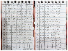
Here's an example of what went into my notebook after doing a lot of step wedge exposures for my last round of contrast calibration for my RH Analyser:
PhotoGrid_1581542662952.jpg
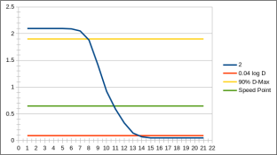
I then had to graph these numbers in a spreadsheet and try to figure out where their graphs crossed certain points for each grade:
contrast-2.png

I'd love to go straight from the densitometer into my device, then let my device crunch all the numbers internally to find those crossing points.
 

koraks

Moderator
Moderator
Joined
Nov 29, 2018
Messages
22,764
Location
Europe
Format
Multi Format
[/quote]These sorts of thoughts are always welcome. One of the most frustrating parts of working on a project like this is simply not having anyone to meaningfully discuss the finer details with.[/quote]
I know! Thanks for the time reading my ramblings and going into them seriously. If anything, it's nice to vent things from time to time.

In addition to the AMS73211, I've also come across the AS7341. The AS7341 seems to be far better suited to sampling a wide swath of the spectrum and figuring out how to best translate it into something within "ISO Status M" (which is what I'd probably want to use as my measurement system since its how color negatives are typically measured on a densitometer.
Indeed. I also came across the 7341, but haven't gone beyond a quick look at the datasheet. IIRC it didn't seem to add much in terms of sensitivity on top of the 73211 and I didn't see a compelling need for improved color separation. Although it may be nice, especially because with a 3 channel sensor, there's always some overlap between (most notably) green & blue. Having a some more, and especially narrower, response peaks might be convenient as it will make calibration and onboard signal processing a little less complex. But I fear it will come at the cost of sensitivity, which is something I'm quite concerned with as you can tell by now. This is mostly based on some informal testing in my own darkroom/enlarger setup combined with the design starting points of the light source & color analyzer system I'm working on. Turns out I need the combination of speed and sensitivity.

Even if there's no ready-made sensor with an I2C interface that's up to the job, a custom implementation can be front-ended by a small microcontroller that speaks I2C to the main device.
That's exactly what I intend(ed) to do. I'm still torn a little if I want to make the main processor of my system talk directly (via Wire) with the ADC or if I'm going to put a peripheral 328p on the sensor board. I'm probably going with the former and dispense with the additional uC, since I'm going to use an ESP8266 for the main board and that should easily deal with the tasks I have in mind for it.

For general metering, I'm currently running the TCS3472 at its "max low-light sensitivity" setting. That means a gain of 60X, and an integration time of 614ms. This actually works fine, and having it take 1-2 seconds per reading is actually reasonable for the use case. (The RH Analyser is similar in how long it takes for a stable reading.)
Yes, I imagine that would work OK for your device. For my setup, I expect I'll need to run series of 10-20 measurements (each probably consisting of several samples), so I need to get the sampling time down to something like 5-20ms ideally. Still working on it, but I'm making progress as of today...

I decided to go with Lux simply because the process of converting readings from these sensors into Lux is well documented, existing calibrated Lux meters are available as a reference for calibrating the sensor's output, and the ISO specs on paper/film characteristic curves are all specified in terms of a logarithmic scale of lux-seconds.
Especially the latter is a compelling argument, IMO. Fortunately, if you know W/m2 + wavelength, you can get to lux.

One thing that really sets my project apart from many similar projects is a few key points:
Yes, I gathered all these aspects from your posts, blog & GitHub. Your project looks magnificent in every respect; I admire your ability to combine tidiness with a thorough design approach and apparently a pretty darn quick development process!
 
OP
OP
dkonigs

dkonigs

Subscriber
Joined
Sep 17, 2009
Messages
358
Location
Mountain View, CA
Format
Multi Format
That's exactly what I intend(ed) to do. I'm still torn a little if I want to make the main processor of my system talk directly (via Wire) with the ADC or if I'm going to put a peripheral 328p on the sensor board. I'm probably going with the former and dispense with the additional uC, since I'm going to use an ESP8266 for the main board and that should easily deal with the tasks I have in mind for it.

Any particular reason for using an ESP8266? If you're going with a uC from the Espressif line, I'd strongly recommend using an ESP32 instead. Its a far more capable module, has a lot more I/O (the ESP8266 is bare-minimum in that department), and has a much better SDK. I used it at the core of my previous project which needed WiFi capabilities.

For this project, I decided to go with the STM32. I picked it because I didn't need WiFi, and because it has much fancier I/O capabilities. So I didn't need to worry about running out of I/O pins, or being creative with how I used them. (Its support for USB was also really nice, which I'm not sure Espressif has yet managed in their mainstream products.)

Yes, I imagine that would work OK for your device. For my setup, I expect I'll need to run series of 10-20 measurements (each probably consisting of several samples), so I need to get the sampling time down to something like 5-20ms ideally. Still working on it, but I'm making progress as of today...
Okay, now I'm quite curious as to what you're trying to build.

Yes, I gathered all these aspects from your posts, blog & GitHub. Your project looks magnificent in every respect; I admire your ability to combine tidiness with a thorough design approach and apparently a pretty darn quick development process!
Thanks! This whole project feels like its moving too slowly, but when you stand back and look from afar... it does seem to be moving pretty quick. I started working on the hardware back in October, finally got the first revision of hardware fully assembled in early December, and have been working on the firmware ever since. I still have a long to-do list, but its amazing just how close I actually am to a "usable device."
 

albada

Subscriber
Joined
Apr 10, 2008
Messages
2,172
Location
Escondido, C
Format
35mm RF
Stops are not a unit of exposure.
I use "stops" as a unit of exposure per the following equation:

seconds = 2^timestops​

Thus timestops = log2 seconds. "Timestops" would be better called EV, analogous to the EVs for shutter-speeds. A disadvantage of timestops is that many people would regard them as weird when they become negative as exposure drops below one second. Whatever we wish to call them, I prefer timestops because they fit well with using EV for LED power-levels. One can interchange the two freely (within reciprocity limits of the paper), similar to the linked shutterspeeds and apertures on many cameras from the 1950s.
 

radiant

Member
Joined
Aug 18, 2019
Messages
2,135
Location
Europe
Format
Hybrid
I use "stops" as a unit of exposure per the following equation:

Yes, totally is. It is the only way to do this. Playing with seconds is pain in the ass :smile:

Thinking in stops is so much easier, you don't need to care about how large is the base time. Effect for example exposing 0.2 stops more yields the same whatever your base time is.
 

koraks

Moderator
Moderator
Joined
Nov 29, 2018
Messages
22,764
Location
Europe
Format
Multi Format
Any particular reason for using an ESP8266? If you're going with a uC from the Espressif line, I'd strongly recommend using an ESP32 instead. Its a far more capable module, has a lot more I/O (the ESP8266 is bare-minimum in that department), and has a much better SDK. I used it at the core of my previous project which needed WiFi capabilities. For this project, I decided to go with the STM32. I picked it because I didn't need WiFi, and because it has much fancier I/O capabilities. So I didn't need to worry about running out of I/O pins, or being creative with how I used them. (Its support for USB was also really nice, which I'm not sure Espressif has yet managed in their mainstream products.)
Not really; I had used one before in a previous project and when I was ordering stuff, I ordered a couple of these. I've been using it in this project for now, but I can still easily change my mind towards an ESP32 or something entirely else. And perhaps I will; the WiFi connectivity of the ESP is nice at this stage and perhaps it's something I'll even implement in the final version, but it's also possible it's going to be non-networked. For me, Arduino IDE support is convenient as I quite like the environment, although I'm not exactly married to it either (and the compilers are slow for some reason, particularly for the ESP family). It's funny you use the STM32; a few weeks ago I was also reading about them. Very interesting product line! Indeed, onboard/native USB support is very convenient. I take it you don't use the Arduino IDE to program them? What platform/IDE do you use for these?
Btw, initially I planned on doing this with an arduino nano/Atmel328p, but I've scratched that option. Too limited in nearly every way, and too many far superior options out there.

Okay, now I'm quite curious as to what you're trying to build.
Nothing very fancy; basically just a timer/controller for a LED enlarger light source with an integrated color analyzer. The main aim is to reduce the number of test strips needed with RA4 printing. Or, perhaps more accurately, the main aim is to have fun with electronics and make something in the process that is somewhat useful in the darkroom as well...
The concept is fairly simple; use the color analyzer to measure an area on the baseboard (most likely one that will need to come out neutral/grey in color), and then adjust the RGB output to match the color ratios for a stored calibration entry. Simple idea, complex to get to work in real life, as usual. It's essentially a somewhat smarter evolution of my current RGB color enlarger, which works quite well - but why leave something alone that works OK, right?
Interestingly, LiCi (who made excellent color analyzers back in the day) essentially had a system like this in the 1990s (!)

If all that works, then it's also fairly straightforward to implement some basic exposure control and contras measurement for multigrade B&W. So my focus is now on color as that's the demanding part; if that works, the rest will follow.

Thanks! This whole project feels like its moving too slowly, but when you stand back and look from afar... it does seem to be moving pretty quick. I started working on the hardware back in October, finally got the first revision of hardware fully assembled in early December, and have been working on the firmware ever since. I still have a long to-do list, but its amazing just how close I actually am to a "usable device."
It seems the usable device is always just around the corner, isn't it? :wink:
Well, not for me; I'm really at the early stages of testing. I'm essentially re-engineering every aspect of my existing setup from the ground up - new light source, new current controllers, new control box/UI, and the sensitometry/color analyzer is of course an entirely new addition.
It's fun though; I learn a lot in the process. I quite enjoy making my own PCB's as well at the moment. They're rather DIY-quality of course, but it's kind of nice to go from DesignSpark virtual space to a solder-masked PCB in your hand within a day.
 

radiant

Member
Joined
Aug 18, 2019
Messages
2,135
Location
Europe
Format
Hybrid
I'm using Arduino Mega 2560 on my enlarger timer / analyser. It has 128x64 monochrome display for UI. I'm using a PS/2 keyboard for inputs - pretty easy way to get quite a few keys in ready made form factor! I'm not facing any resource issues (computing/IO) with Atmega 2560 on my device.

Other Arduino-compatible solutions would be Arduino Due - a fast ARM Cortex-M3 chip and basically really close to STMF4-series for example. Huge amount of IO in Due.

Also Teensy 4.1 would be a good choice: you will not run out of computing power :smile: And really versatile IO. Totally compatible with Arduino IDE + supported toolchains. Paul is amazing guy.
 

koraks

Moderator
Moderator
Joined
Nov 29, 2018
Messages
22,764
Location
Europe
Format
Multi Format
When it comes to bang for the buck, products such as the esp series and stm32 are pretty hard to beat. Teensy etc are also nice, but usually more costly. Atmega moves at a snail's pace compared to the other options. Likely plenty fast enough for many applications, but I no longer see the point in working with slower options if much faster & more functionality is available for the same price or even much less...
 

radiant

Member
Joined
Aug 18, 2019
Messages
2,135
Location
Europe
Format
Hybrid
When it comes to bang for the buck, products such as the esp series and stm32 are pretty hard to beat. Teensy etc are also nice, but usually more costly. Atmega moves at a snail's pace compared to the other options. Likely plenty fast enough for many applications, but I no longer see the point in working with slower options if much faster & more functionality is available for the same price or even much less...

Unless you are doing this for commercial products, the cost of Teensy is practically nothing compared to other investments in the project.

Arduino Mega 2560 beats ESP32 for example in terms of GPIO & perephials :wink: It depends what you need..
 
OP
OP
dkonigs

dkonigs

Subscriber
Joined
Sep 17, 2009
Messages
358
Location
Mountain View, CA
Format
Multi Format
Not really; I had used one before in a previous project and when I was ordering stuff, I ordered a couple of these. I've been using it in this project for now, but I can still easily change my mind towards an ESP32 or something entirely else. And perhaps I will; the WiFi connectivity of the ESP is nice at this stage and perhaps it's something I'll even implement in the final version, but it's also possible it's going to be non-networked. For me, Arduino IDE support is convenient as I quite like the environment, although I'm not exactly married to it either (and the compilers are slow for some reason, particularly for the ESP family). It's funny you use the STM32; a few weeks ago I was also reading about them. Very interesting product line! Indeed, onboard/native USB support is very convenient. I take it you don't use the Arduino IDE to program them? What platform/IDE do you use for these?
Btw, initially I planned on doing this with an arduino nano/Atmel328p, but I've scratched that option. Too limited in nearly every way, and too many far superior options out there.

I pretty much refuse to jump on the "Arduino all the things!" bandwagon that's popular these days. I'll sometimes use an Arduino Nano as a bench-test device, but that's as far as I go. I much prefer to use the real SDK for whatever platform I'm working with. For the ESP32, that means the ESP-IDF stack (for which I've configured Eclipse to work with). For the STM32, that means the whole STM32CubeMX//HAL stack (with the Eclipse-based STM32CubeIDE), though I've pushed the files around into a saner directory structure than whatever weird corporate-mandated conventions they use out of the box. (Code for these project is on my Github account, if you want to take a peek.)

Nothing very fancy; basically just a timer/controller for a LED enlarger light source with an integrated color analyzer. The main aim is to reduce the number of test strips needed with RA4 printing.

Then why do you need such fast response times from your sensor?

Even if you can't do the whole color analyzer bit, its amazing just how quickly you can zero in on the correct exposure by simply using f-stop timing. Just take notes so you have a reasonable starting point for each enlargement size. Right now when I do RA4 (with my RH box), I'm usually able to get my exposure in just one or two test strips (I usually do two at once, since my smallest processing drum can hold two at a time.) Of course fine tuning the color balance is where the real effort is, but even there a reasonable starting point gets you most of the way there.

Or, perhaps more accurately, the main aim is to have fun with electronics and make something in the process that is somewhat useful in the darkroom as well...
This is always a good goal. One problem I keep running into whenever I "survey the field" of existing products/apps/devices in this space is that there are tons of options that all do 80% of what I want. But if I want to build something to cover that last 20%, I first have to duplicate that 80%. (Which makes it hard to get motivated enough to start such projects.)

Interestingly, LiCi (who made excellent color analyzers back in the day) essentially had a system like this in the 1990s (!)
I'm tempted at some point to start looking more closely at these old devices. Maybe even disassemble the probe from that ColorStar 3000 I have sitting in a box. Another benefit of this field is that you can look up patents for a lot of these old devices... And those patents are all now expired! So, tons of potential research fodder you can pour through for ideas. (Those patents were also written before the era of lawyers filling the text with gobbledegook, so they actually provide a meaningful description of what's being patented.)

It seems the usable device is always just around the corner, isn't it? :wink:
One problem is that there's a big difference between "good enough for me" and "good enough for someone else." For example, I'm okay plugging a programmer device into the box to update the firmware. Other people would rather install updates off a USB stick.
It is also amazing how PCB manufacture and surface-mount assembly has become completely accessible to the hobbyist today. And I'm glad it has, because most modern components are really only offered in form factors that are meant to be used this way. (I generally design the electronics in KiCad, and have previously used OSH Park for the PCB. However, recently, I've switched to mostly using JLCPCB. OSH Park is just too slow and too expensive the moment you want something bigger thank a trinket board.)
 

koraks

Moderator
Moderator
Joined
Nov 29, 2018
Messages
22,764
Location
Europe
Format
Multi Format
I pretty much refuse to jump on the "Arduino all the things!" bandwagon that's popular these days. I'll sometimes use an Arduino Nano as a bench-test device, but that's as far as I go. I much prefer to use the real SDK for whatever platform I'm working with. For the ESP32, that means the ESP-IDF stack (for which I've configured Eclipse to work with). For the STM32, that means the whole STM32CubeMX//HAL stack (with the Eclipse-based STM32CubeIDE), though I've pushed the files around into a saner directory structure than whatever weird corporate-mandated conventions they use out of the box. (Code for these project is on my Github account, if you want to take a peek.)
Yes, understandable. I did indeed take a quick peek at your code, which raised my question in the first place. I might look into different environments, although I have to admit I'm quite satisfied with the Arduino IDE for now and the many forum posts, experiences and solutions to common problems out there. For someone like me with only limited experience programming embedded systems, this is a great help.

Then why do you need such fast response times from your sensor?
In theory, you'd say it wouldn't have to be that fast. You could take a reading of, let's say, a cloud, and since you know it's going to be more or less neutral in tone, you can calculate the required RGB settings based on a previously made paper profile. That's the theory...but I'm not so optimistic that this will actually work. In practice, I'm afraid it's going to be an iterative approach where you do a measurement, change the RGB mix, do a measurement, etc. That means that dozens of individual samples may be needed to find a solution. With integration times over 50ms or so, that can quickly become annoying. With the AS73211, I found that useful resolution for color measurement required fairly long integration times of 256ms upwards.

Right now when I do RA4 (with my RH box), I'm usually able to get my exposure in just one or two test strips (I usually do two at once, since my smallest processing drum can hold two at a time.) Of course fine tuning the color balance is where the real effort is, but even there a reasonable starting point gets you most of the way there.
Yes, I have the same experience. You might say I'm solving a problem that isn't really a problem in the first place :wink: Although I do sometimes mess about with film that's either grossly expired or otherwise severely compromised, and that makes it a little more difficult to get close to a good result.
Evidently, any time savings I could achieve with a quasi-automated setup are already destroyed by the time I spent on developing this system. But like I said, it's a fun project!

I'm tempted at some point to start looking more closely at these old devices. Maybe even disassemble the probe from that ColorStar 3000 I have sitting in a box.
I did exactly this - opened up the probe of my Colorstar and had a quick look inside to see how they approached the issue. It seems they used an array of 3 photodiodes next to each other with an optical waveguide and a transimpedance amplifier using adjustable offset opamps. All early 1990s components, and with today's electronics, it's fairly easy to work around some of the problems they must have faced with relatively inefficient photodiodes and much more noisy and high-offset opamps. I ended up using a Hamamatsu S9032 triple photodiode and AD8605 opamps in my setup, but I may switch to a different photodiode (perhaps the S9702) in a later version as the S9032 is already a bit outdated. Unfortunately, the choice of RGB photodiodes is limited to only a handful and some of the potentially interesting products are either unobtainium or already phased out and replaced with I2C sensors.

One problem is that there's a big difference between "good enough for me" and "good enough for someone else." For example, I'm okay plugging a programmer device into the box to update the firmware. Other people would rather install updates off a USB stick.
It is also amazing how PCB manufacture and surface-mount assembly has become completely accessible to the hobbyist today. And I'm glad it has, because most modern components are really only offered in form factors that are meant to be used this way. (I generally design the electronics in KiCad, and have previously used OSH Park for the PCB. However, recently, I've switched to mostly using JLCPCB. OSH Park is just too slow and too expensive the moment you want something bigger thank a trinket board.)
Yes, true that, on both accounts. Fortunately, I can settle for 'good enough for me', as I don't have the ambition to engineer this into a marketable product. But it does help that so many resources are available to hobbyists today in terms of acquisition of components and prototyping various parts. I must confess I haven't tried outsourcing PCB manufacturing myself, mostly because I like the quick turnaround I get when making them myself and because the hardware is mostly simple enough to stick with single sided PCB's. I initially used ExpressPCB for PCB design, but quickly grew wary of its many limitations. I currently use DesignSpark for this purpose, which works well enough for me. I did have a look at KiCad, but honestly can't recall why I settled for DesignSpark in the end. I might switch at some point, although currently, it seems that DesignSpark does what I need it to do. That, combined with LTSpice for circuit simulation.
 
OP
OP
dkonigs

dkonigs

Subscriber
Joined
Sep 17, 2009
Messages
358
Location
Mountain View, CA
Format
Multi Format
I did exactly this - opened up the probe of my Colorstar and had a quick look inside to see how they approached the issue. It seems they used an array of 3 photodiodes next to each other with an optical waveguide and a transimpedance amplifier using adjustable offset opamps. All early 1990s components, and with today's electronics, it's fairly easy to work around some of the problems they must have faced with relatively inefficient photodiodes and much more noisy and high-offset opamps. I ended up using a Hamamatsu S9032 triple photodiode and AD8605 opamps in my setup, but I may switch to a different photodiode (perhaps the S9702) in a later version as the S9032 is already a bit outdated. Unfortunately, the choice of RGB photodiodes is limited to only a handful and some of the potentially interesting products are either unobtainium or already phased out and replaced with I2C sensors.
I should keep these parts in mind when I get to that phase of my project, to see if they're more viable than the fully-integrated I2C sensors everyone is using nowadays. Of course I don't really have much analog electronics experience, so who knows what I'll actually be able to get better results with. FWIW, I've frequently heard that the ESP microcontrollers don't have very good ADCs, which would obviously matter for such sensors. If I did use something like this, I'd either put an I2C ADC inside my "meter probe" or a dedicated small microcontroller with its own good ADC (that would speak I2C to the main unit.)
 

koraks

Moderator
Moderator
Joined
Nov 29, 2018
Messages
22,764
Location
Europe
Format
Multi Format
Don't hesitate to give me a holler if you want to dive into the analog part at some point.
You're right about the adc ports; in fact, I didn't even bother trying. I use an omnipresent ads1115 for this purpose, which appears to be a good performer in this task.
 

albada

Subscriber
Joined
Apr 10, 2008
Messages
2,172
Location
Escondido, C
Format
35mm RF
So there are four of us who are making controller/timers!

My goal is to (1) drive the three LED-chains in my home-made light-head by specifying attenuations in EV, and (2) a simple fstop timer.
I'm using an Arduino Uno, which works fine in all ways for this project, except that the 8-bit PWM has poor accuracy when attenuating LEDs by over 4 stops or so. The error is 5.4% at an attenuation of 4.9 stops. I've thought of a couple of tricks to reduce this error, but I might not bother because such a dim LED is contributing little density to the image, so a 5% error should not be perceivable. The display is a 16x2 character LCD. The hard part was finding one with a red backlight. I'm using this one that has RGB backlights:
https://www.digikey.com/en/products/detail/newhaven-display-intl/NHD-0216K1Z-NS-RGB-FBW-REV1/2172436
I'm using this project box because it's the right size and has a sloped control-panel: https://www.digikey.com/en/products/detail/bud-industries/PC-11491/439698
I've written all the software (firmware), and the physical installation and wiring of display and buttons and connectors are done. I am now in the midst of installing and soldering in the support electronics.

I am a software geek (CS degree) with a strong electronics background, and I've programmed embedded systems for most of my career. I'm fine with digital electronics, but weak with analog. For this project, I'm using solely through-hole on a breadboard (in addition to the Uno board). Maybe after this experience, I'll follow koraks example and create this project over, but using a proper PCB and perhaps even surface-mount. And an MCU with better PWM.

I'm also making this controller be a process timer that merely counts seconds up (from zero) forever. I added this feature because it adds no hardware (aside from a button), and it's useful for timing developing/stopping/fixing/washing. But I want to re-zero the timer at each new step, so I'm thinking of adding a microphone (with some analog electronics) to detect a sustained loud noise (my voice) to zero the timer. That would let me avoid touching the timer with my wet gloves.
 

koraks

Moderator
Moderator
Joined
Nov 29, 2018
Messages
22,764
Location
Europe
Format
Multi Format
And an MCU with better PWM.
You may want to look into the pca9685. It's a 12 bit 16 channel pwm controller that connects via I2C. Works very well for this application.

I'm also making this controller be a process timer that merely counts seconds up (from zero) forever.
I implemented this as a separate box that sits above my sink. It has a real time clock (red segment display) with hh:mm:ss, and a separate countdown timer (mm:ss) that beeps every 30 seconds during countdown. Time is synced over ntp so I never have to set the time manually. Countdown timer input is done with a rotary. I'm very happy with it; much more convenient than having to look in the direction of the enlarger when processing film or paper. Plus I have a clearly visible clock in my darkroom this way, which is simply convenient.
My enlarger controller also has a function that counts up from 0, but it's used for burning/dodging.
 
OP
OP
dkonigs

dkonigs

Subscriber
Joined
Sep 17, 2009
Messages
358
Location
Mountain View, CA
Format
Multi Format
So there are four of us who are making controller/timers!
Almost starting to think we need to fork off into a separate discussion group for this stuff!

The display is a 16x2 character LCD. The hard part was finding one with a red backlight. I'm using this one that has RGB backlights:
https://www.digikey.com/en/products/detail/newhaven-display-intl/NHD-0216K1Z-NS-RGB-FBW-REV1/2172436
I'm using this project box because it's the right size and has a sloped control-panel: https://www.digikey.com/en/products/detail/bud-industries/PC-11491/439698
Make sure you darkroom-test your display. I did a lot of testing before getting deep into my project, and even the "red" OLED display I tested wasn't safe by itself. I ultimately ended up deciding to go with a yellow OLED display and put it behind some Rosco Fire Red #19 sandwiched between some sheets of transparent plastic.
Specifically, this is the display I'm using:
https://www.newhavendisplay.com/nhd31225664ucy2-p-3537.html
(I've used it for other projects, so I'm somewhat fond of it. Its also the largest graphic OLED I can easily get, without going to something designed for smartphones.)

Here's a Facebook post I made detailing some of my own experiments in this area:
https://www.facebook.com/groups/576750649124280/permalink/2104093769723286/

I am a software geek (CS degree) with a strong electronics background, and I've programmed embedded systems for most of my career. I'm fine with digital electronics, but weak with analog.
I'm probably similar in this regard. Okay, I've never really done embedded systems professionally (assuming smartphones don't count here), but it has been an on-again/off-again hobby for a long time. My first experiences with embedded programming were on the M68HC11 back in the day.

I'm also making this controller be a process timer that merely counts seconds up (from zero) forever. I added this feature because it adds no hardware (aside from a button), and it's useful for timing developing/stopping/fixing/washing. But I want to re-zero the timer at each new step, so I'm thinking of adding a microphone (with some analog electronics) to detect a sustained loud noise (my voice) to zero the timer. That would let me avoid touching the timer with my wet gloves.
For process timing with paper, I just use a simple GraLab 300 that's sitting above my trays. I figured having one was a mandatory piece of "darkroom decoration," and it does this job just fine. However, paper timing is really simple and consistent, so setting/resetting on that big dial isn't much of an issue. (With film processing, where its a bit more complex, I'll either use an app on my phone or the process timer in my Jobo CPP-3.)
 

koraks

Moderator
Moderator
Joined
Nov 29, 2018
Messages
22,764
Location
Europe
Format
Multi Format
Almost starting to think we need to fork off into a separate discussion group for this stuff!
Well, we could make a separate thread at least to collect posts about various aspects of timer, exposure and light source DIY electronics. For one thing it may prevent further fouling up your thread (for which I kind of feel guilty...)
 
Photrio.com contains affiliate links to products. We may receive a commission for purchases made through these links.
To read our full affiliate disclosure statement please click Here.

PHOTRIO PARTNERS EQUALLY FUNDING OUR COMMUNITY:


Ilford ADOX Freestyle Photographic Stearman Press Weldon Color Lab Blue Moon Camera & Machine
Top Bottom