Durst CLS 1840 - Need help and advice :) New Darkroom build.

about to extinct

D
about to extinct

  • 0
  • 0
  • 30
Fantasyland!

D
Fantasyland!

  • 9
  • 2
  • 102
perfect cirkel

D
perfect cirkel

  • 2
  • 1
  • 121
Thomas J Walls cafe.

A
Thomas J Walls cafe.

  • 4
  • 6
  • 286

Recent Classifieds

Forum statistics

Threads
198,745
Messages
2,780,278
Members
99,693
Latest member
lachanalia
Recent bookmarks
0

ic-racer

Member
Joined
Feb 25, 2007
Messages
16,544
Location
USA
Format
Multi Format
:D I will have to investigate the reason for this!

I'm pretty sure on mine it was from the shutter jamming. When I got mine the shutter was disconnected and left open. I repaired the shutter and replaced the resistor, and it worked fine, nothing else was damaged.
 

gary mulder

Member
Joined
Nov 29, 2006
Messages
126
Format
4x5 Format
I have now also ordered a zmpt101b board to create the feedback loop for the dimmer. Gary, you mentioned it was not possible to get a reliable RMS measurement from this. How so?

Yes I abandoned that idea. It came to a point that I concluded that it needed a second microprocessor or better programming skills than mine.
 

gary mulder

Member
Joined
Nov 29, 2006
Messages
126
Format
4x5 Format
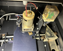
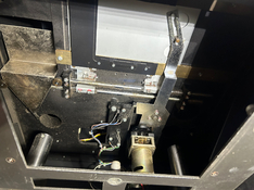
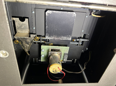
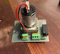
Here is the shutter on my 2000. I wonder what Gary's looks like.

Al three are different. Last picture is from my spare parts.
 

Attachments

  • IMG_0283.jpg
    IMG_0283.jpg
    391 KB · Views: 46
  • IMG_0284.jpg
    IMG_0284.jpg
    404.1 KB · Views: 45
  • IMG_0285.jpg
    IMG_0285.jpg
    356.9 KB · Views: 47
  • IMG_0286.jpg
    IMG_0286.jpg
    387.9 KB · Views: 46
OP
OP
reneboehmer

reneboehmer

Member
Joined
Oct 6, 2024
Messages
92
Location
Austria
Format
Analog
durst4.jpg

Been working on the enlarger today.

It seems like the shutter is a very simple mechanism. You have 3 connections. Two are - and one is +. Once you connect the second -, the mechanism will do one movement, opening the shutter. Connect it again and it will close the shutter. This is controlled by the 24v relay mounted on the old-school PCB board. My friend and I will write some code to calibrate the shutter precisely. Well, if it's necessary, that is.

We figured out that we had to use some mosfets in order to control the ssr relay. It seems like the esp can not output enough amps to trigger the relay. Still a bit puzzled, but we will get there.

Additionally, my friend Angelo, who is smarter than me, had the idea of using a photocell, that's watching the light output, as a feedback loop for our dimmer. His idea is that the signal that's obtained from the cell is already smoothed out and ready to be used. We will have to figure out some sort of algorithm to deal with the delays. All that is, of course, only, should testing show that the output is not consistent without it.
 

koraks

Moderator
Moderator
Joined
Nov 29, 2018
Messages
22,703
Location
Europe
Format
Multi Format
We figured out that we had to use some mosfets in order to control the ssr relay. It seems like the esp can not output enough amps to trigger the relay.

Hm, that doesn't make all that much de de really. An SSR typically has a logic level input; it doesn't draw any appreciable amount of current.


His idea is that the signal that's obtained from the cell is already smoothed out and ready to be used.

Depends on the type of sensor and the associated circuitry. But yes, you can do a closed loop system on this basis. You may want to Google "PID controller"; you'll find Arduino libraries that you can simply plug your numbers into and you don't have to worry too much about the underlying math/algorithms.
 
OP
OP
reneboehmer

reneboehmer

Member
Joined
Oct 6, 2024
Messages
92
Location
Austria
Format
Analog
Hm, that doesn't make all that much de de really. An SSR typically has a logic level input; it doesn't draw any appreciable amount of current.
We are a bit puzzled :D Maybe it's just an oversight we were not yet able to entangle.


Depends on the type of sensor and the associated circuitry. But yes, you can do a closed loop system on this basis. You may want to Google "PID controller"; you'll find Arduino libraries that you can simply plug your numbers into and you don't have to worry too much about the underlying math/algorithms.
Thanks for that! I will check it out tomorrow :smile:
 

koraks

Moderator
Moderator
Joined
Nov 29, 2018
Messages
22,703
Location
Europe
Format
Multi Format
Have a look at post #54

Thanks; I forgot about that one.
So it's a generic SSR40DA relay; the big question is whether there's a datasheet available. Probably not, so some measurements could be taken, although it's probably easier to just forego that and simply hook up the relay through a small signal mosfet (BSS123, 2n7000 etc.) or even a small NPN and run it off of 5V instead of the ESP's 3.3V logic level.
1735377144238.png
 

gary mulder

Member
Joined
Nov 29, 2006
Messages
126
Format
4x5 Format
Thanks. Confirms that use of a 5V microcontroller is less complicated.
 
OP
OP
reneboehmer

reneboehmer

Member
Joined
Oct 6, 2024
Messages
92
Location
Austria
Format
Analog
Thanks; I forgot about that one.
So it's a generic SSR40DA relay; the big question is whether there's a datasheet available. Probably not, so some measurements could be taken, although it's probably easier to just forego that and simply hook up the relay through a small signal mosfet (BSS123, 2n7000 etc.) or even a small NPN and run it off of 5V instead of the ESP's 3.3V logic level.
View attachment 386333

Koraks, thank you once again!
 
OP
OP
reneboehmer

reneboehmer

Member
Joined
Oct 6, 2024
Messages
92
Location
Austria
Format
Analog
So it's a generic SSR40DA relay; the big question is whether there's a datasheet available. Probably not, so some measurements could be taken, although it's probably easier to just forego that and simply hook up the relay through a small signal mosfet (BSS123, 2n7000 etc.) or even a small NPN and run it off of 5V instead of the ESP's 3.3V logic level.
Yes, we will probably ditch the SSR and switch the fan using the other relay board we also installed. It can handle the load and works fine with the esp's signals.
 

koraks

Moderator
Moderator
Joined
Nov 29, 2018
Messages
22,703
Location
Europe
Format
Multi Format
Thanks. Confirms that use of a 5V microcontroller is less complicated.

Depends on how you look at it. ESP-series uC's are more flexible and vastly more powerful, so things like multitasking (which made you consider adding a second controller for) are relatively easy to implement. On the more basic 8-bit AVR controllers, it takes a little more ingenuity to get that done. On an AVR, you have to arrange something with periodic polling of tasks or perhaps using timer interrupts if it's really time critical. On an ESP, you can simply create multiple tasks that the operating system will then balance for you without having to worry about it.
As always, it's a compromise.

Yes, we will probably ditch the SSR and switch the fan using the other relay board we also installed. It can handle the load and works fine with the esp's signals.

Yeah, I would have expected the SSR you have there to do fine with 3.3V signals. But again, it depends on the specifications, which may not be easy to find for generic components like these. I personally prefer to only use parts for which I can find a decent datasheet. Most DIY-oriented relay modules (SSR or otherwise) accept logic level inputs regardless if they're 3.3 or 5V.
 
OP
OP
reneboehmer

reneboehmer

Member
Joined
Oct 6, 2024
Messages
92
Location
Austria
Format
Analog
The simplest replacement is a working EST1000, or a much simpler and functioning enlarger altogether.

That might be true. It would have been easy to replace the two capacitors on my unit and call it done. But that would not be any fun at all. It's a pleasure to learn and tinker about.
 

koraks

Moderator
Moderator
Joined
Nov 29, 2018
Messages
22,703
Location
Europe
Format
Multi Format
Indeed. I said that really only to imply that it's in the end always a compromise, and we tend to compromise for our own personal and subjective motives, capabilities, preferences, prejudices and requirements. Replacing the original capacitors IMO is just as valid as using an Arduino-based circuit, which is just as valid as scrapping the whole light source and DIY-ing a computer-controlled LED device.
 
OP
OP
reneboehmer

reneboehmer

Member
Joined
Oct 6, 2024
Messages
92
Location
Austria
Format
Analog
Update

A huge thank you to everyone who lent their expertise in sourcing parts and brainstorming approaches for my power supply project! I'm thrilled to report that I'm nearing completion.

I've put together a short private YouTube video showcasing the system's current functionality, even though it's not yet connected to an enlarger. This has been my first step into DIY electronics and programming, and I'm genuinely pleased with the progress so far. Once the project is fully finished, I'll be sharing all the code and a comprehensive list of the parts I used.

I'm still refining the closed-loop system, but I might have settled on a solution. My current plan is to monitor the actual light source with an intensity sensor, using that data to inform the feedback loop. This seems more logical than attempting to measure high-voltage true RMS at the power supply's lamp port, especially since I haven't found a reliable way to accurately measure that voltage. Measuring at the lamp housing simply makes more sense, as it directly reflects what we need to control. However, if anyone has insights on accurate high-voltage true RMS measurement, I'd certainly be open to suggestions!
 

koraks

Moderator
Moderator
Joined
Nov 29, 2018
Messages
22,703
Location
Europe
Format
Multi Format
if anyone has insights on accurate high-voltage true RMS measurement, I'd certainly be open to suggestions!

One easy and relatively say approach would be to take a small transformer (e.g. 230V to 12V), connect its primary across the lamp contacts and rectify + filter the secondary. Measure that rectified voltage, which you can scale and amplify as you desire. Personally I'd make a simple opamp-based differential amplifier with a static offset so that you only measure fluctuations that are meaningful, then scale that as needed to feed it into the ESP32's ADC. Note that the ADC on the ESP32 isn't very linear, but this will not be a major concern. Due to the filtration of the signal, there will be some delay/dampening so in your PID you'll have to prevent oscillations. That's a matter of judicious programming.

But measuring actual light output is a more sensible approach overall.
 
OP
OP
reneboehmer

reneboehmer

Member
Joined
Oct 6, 2024
Messages
92
Location
Austria
Format
Analog
One easy and relatively say approach would be to take a small transformer (e.g. 230V to 12V), connect its primary across the lamp contacts and rectify + filter the secondary. Measure that rectified voltage, which you can scale and amplify as you desire. Personally I'd make a simple opamp-based differential amplifier with a static offset so that you only measure fluctuations that are meaningful, then scale that as needed to feed it into the ESP32's ADC. Note that the ADC on the ESP32 isn't very linear, but this will not be a major concern. Due to the filtration of the signal, there will be some delay/dampening so in your PID you'll have to prevent oscillations. That's a matter of judicious programming.

But measuring actual light output is a more sensible approach overall.

I have heard this advice from a friend too, but this seems a bit too complicated for my skill set. I figured getting the light output might be the more accessible solution for me.
 

koraks

Moderator
Moderator
Joined
Nov 29, 2018
Messages
22,703
Location
Europe
Format
Multi Format
Well, regardless if it's more accessible, more relevant is that light output is actually what you want to control. Of course, there's a direct correlation between bulb voltage and light output, but this is affected by factors like bulb aging etc. So measuring light output may be technically simpler (there are several ready-made modules you could use), it's also better!
 

ic-racer

Member
Joined
Feb 25, 2007
Messages
16,544
Location
USA
Format
Multi Format
One thing I see different is that in my CLS2000, the lamp pre-warm does not eminate any light.
 
Photrio.com contains affiliate links to products. We may receive a commission for purchases made through these links.
To read our full affiliate disclosure statement please click Here.

PHOTRIO PARTNERS EQUALLY FUNDING OUR COMMUNITY:


Ilford ADOX Freestyle Photographic Stearman Press Weldon Color Lab Blue Moon Camera & Machine
Top Bottom