Durst CLS 1840 - Need help and advice :) New Darkroom build.

submini house

A
submini house

  • 0
  • 0
  • 42
Diner

A
Diner

  • 4
  • 0
  • 85
Gulf Nonox

A
Gulf Nonox

  • 9
  • 3
  • 109
Druidstone

A
Druidstone

  • 10
  • 3
  • 146
On The Mound.

A
On The Mound.

  • 1
  • 0
  • 87

Forum statistics

Threads
197,814
Messages
2,764,910
Members
99,481
Latest member
chopfalne
Recent bookmarks
0
OP
OP
reneboehmer

reneboehmer

Member
Joined
Oct 6, 2024
Messages
92
Location
Austria
Format
Analog
The EST provides these basic functions to the head after it recieves an ON input from the timer:
Power and timing of the fan including a thermal switch
Regulated power to the lamp, (including low idle current when off)
Power to the shutter and timing for opening and closing

I think that is it, but I hope Gary chimes in with a more detailed description of his masterpiece!

Thank you ic racer for this! Appreaciate the sumup!
 

bardamu

Member
Joined
Jul 1, 2008
Messages
47
Location
Milan, IT
Format
Multi Format
Same here, I would so like to have a modern backup for my EST 1000 too. Mine is 220v though
 

gary mulder

Member
Joined
Nov 29, 2006
Messages
98
Format
4x5 Format
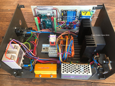
Picture with parts named. This is 230V.
 

Attachments

  • IMG_0602.jpg
    IMG_0602.jpg
    494 KB · Views: 67

ic-racer

Member
Joined
Feb 25, 2007
Messages
16,502
Location
USA
Format
Multi Format
From the picture my guess is a 240v timer input activates the relay in the middle. That signals the Arduino to start its sequence via an input on the Arduino board. Looks like 240V power goes to the ON/OFF switch from the left lower corner and splits 3 ways to the Kemo, fan relay and Meanwell power supply. From the Meanwell, there is a 5v stepdown to run the Arduino.
The Arduino, via PWM, controls the the lamp via the Kemo and the shutter via the relay board (with its 5v power from the 5v stepdown board).

Looks like the original multi-connector to the head (hidden behind the solid state relay) is used to carry the power to the head.

What I can't tell is the reason for the 22 ohm reisstor and relay ( controlling inrush current to bulb?). Though the Kemo says it is "Soft Start."
 
Last edited:

gary mulder

Member
Joined
Nov 29, 2006
Messages
98
Format
4x5 Format
The resistor is put in series with the bulb during startup. Once in idle mode with a preheated bulb the relay is closed.
values;
-preheat voltage across bulb 15V rms max. Ramp-up preheat time ±17 seconds.
-idle 16,8V_rms
-working 117V_rms
 

gary mulder

Member
Joined
Nov 29, 2006
Messages
98
Format
4x5 Format
I fiddled around with a ZMPT101B trying to get a reliable rms measurement without susses. Potentially the ZMPT101B can make it a stabilised power source. If anyone succeeds making it work please let us know.
 
OP
OP
reneboehmer

reneboehmer

Member
Joined
Oct 6, 2024
Messages
92
Location
Austria
Format
Analog
The resistor is put in series with the bulb during startup. Once in idle mode with a preheated bulb the relay is closed.
values;
-preheat voltage across bulb 15V rms max. Ramp-up preheat time ±17 seconds.
-idle 16,8V_rms
-working 117V_rms

Dear Gary,
I am in the process of ordering my parts.
I have some questions regarding the setup.
1) How is the 22Ohm Resistor wired up? 230V Mains ->Resistor -> Lamp or 230V Mains -> Dimmer -> Resistor -> Lamp
2) Do I understand it right, that the resistor is on, only during initial start up, for 17 seconds to bring the lamp to idle temperature and then the relay removes the resistor and the dimmer supplies the 16,8V permanently.
3) The only resistor I found is a 22ohm 50W one. I am afraid that 17 Seconds might damage the resistor.
4) You mentioned preheat voltage across bulb. Can you elaborate on this, I have no background in electronics and wrapping my mind around this is challenging for me :smile:
5) Will the fan always be on when an exposure is being made? (The fan will not be dimmed at all?) I don't understand how that might introduce noise.
6) What kind of fuses do you use in this? I would like to install modern ones in my build. I won't reuse the original case.
Thank you for your insight and help!
All the best!
 
OP
OP
reneboehmer

reneboehmer

Member
Joined
Oct 6, 2024
Messages
92
Location
Austria
Format
Analog
From the picture my guess is a 240v timer input activates the relay in the middle. That signals the Arduino to start its sequence via an input on the Arduino board. Looks like 240V power goes to the ON/OFF switch from the left lower corner and splits 3 ways to the Kemo, fan relay and Meanwell power supply. From the Meanwell, there is a 5v stepdown to run the Arduino.
The Arduino, via PWM, controls the the lamp via the Kemo and the shutter via the relay board (with its 5v power from the 5v stepdown board).

Looks like the original multi-connector to the head (hidden behind the solid state relay) is used to carry the power to the head.

What I can't tell is the reason for the 22 ohm reisstor and relay ( controlling inrush current to bulb?). Though the Kemo says it is "Soft Start."

Hey Ic-Racer,
the kind of lamps I need for my cls1840 are 1kw (https://www.ebay.at/itm/334119318828) like these, right? I don't get why they are 120V, shouldn't I use a 230V one? I live in Europe. In my new power supply, I am planning everything for 230V. I con only find (https://geizhals.at/osram-halogen-studiolampe-230v-gx9-5-1000w-64745-a2141415.html) these. Gary mentioned I should look for a different type. The ones in the first link. What do you think? Am I stupid ? :D
 

gary mulder

Member
Joined
Nov 29, 2006
Messages
98
Format
4x5 Format
Last edited:
OP
OP
reneboehmer

reneboehmer

Member
Joined
Oct 6, 2024
Messages
92
Location
Austria
Format
Analog
I use this resistor https://www.conrad.com/en/p/widap-160127-resistance-wire-22-packaged-100-w-1-1-pc-s-1525269.html
View attachment 384957

Please note that two things are important to understand.
-One. the whole thing is controlled by the Arduino. You will have tot understand programming language for the Arduino. The Kemo Power Control will get the necessary signals from the Adruino.
-Two. The voltage has to be measured in RMS. Do not use a ordinary volt meter.

Thanks, Gary,
I was able to order all parts and I will start soon. Will share the result with you guys.
I will not use an Arduino but an ESP32. I want to use a web interface to control my enlarger. Get rid of the old 230V timer. I'll make my own little timer with an e-ink display. It's cleaner and more precise, I guess.

All the best!
René
 

koraks

Moderator
Moderator
Joined
Nov 29, 2018
Messages
21,252
Location
Europe
Format
Multi Format
3) The only resistor I found is a 22ohm 50W one. I am afraid that 17 Seconds might damage the resistor.

Ohm's law applies to a resistor. If the full voltage it sees is 16V, then I = V/R = 16/22 = ca. 725mA. Furthermore, P = I2*R and this works out as 11-12W. A 50W resistor should survive, provided you offer a means for the heat to be actually dissipated. Do not assume that a 50W resistor all by itself will survive having to dissipate >10W for an extended period of time. Mind you, the lamp is part of the circuit as well, so the resistor won't drop the full 16V most of the time. As the lamp heats up, that will start to eat up some of the power.

I want to use a web interface to control my enlarger.

To each their own, but the utility of this evades me, to be honest. This comes from the guy who does actually control his enlarger from an ESP32, but I never saw the purpose of trying to control it from a computer or smartphone. It's fancy, that's for sure, but I don't really see how it helps in any way to be able to do this.
 
OP
OP
reneboehmer

reneboehmer

Member
Joined
Oct 6, 2024
Messages
92
Location
Austria
Format
Analog
Ohm's law applies to a resistor. If the full voltage it sees is 16V, then I = V/R = 16/22 = ca. 725mA. Furthermore, P = I2*R and this works out as 11-12W. A 50W resistor should survive, provided you offer a means for the heat to be actually dissipated. Do not assume that a 50W resistor all by itself will survive having to dissipate >10W for an extended period of time. Mind you, the lamp is part of the circuit as well, so the resistor won't drop the full 16V most of the time. As the lamp heats up, that will start to eat up some of the power.


To each their own, but the utility of this evades me, to be honest. This comes from the guy who does actually control his enlarger from an ESP32, but I never saw the purpose of trying to control it from a computer or smartphone. It's fancy, that's for sure, but I don't really see how it helps in any way to be able to do this.

Dear Koraks,

Thank you so much for your help! Yes, I calculated this too—with a bit of assistance from ChatGPT, I must admit. :D I went ahead and ordered the same resistor Gary recommended, just to be on the safe side. The ones I initially ordered had an aluminum casing for heat dissipation, but better safe than sorry, right?

I completely agree with you on the second point. I have no intention of incorporating smart tech into my regular operations. My plan is to build a small 3D-printed housing with knobs for adjustments and some old-school graphics on an e-ink display. I haven’t decided yet whether to connect it to the unit with a cable or over Wi-Fi. What I do know is that I want a tactile, physical experience when adjusting my timer. Also, one advantage is that I could do things like F Stop increments in the timer.

Most definitely, I won’t be using a computer or phone for this. The original terminal that comes with the 1840 can be a bit tedious to use—the little buttons can be tricky for me at times. That’s one of the main reasons I’m open to a more modern solution. Alternatively, I might just use a Wallner timer I’ve had sitting in storage. Either way, I’ll incorporate a relay to allow the use of a regular timer.
 

koraks

Moderator
Moderator
Joined
Nov 29, 2018
Messages
21,252
Location
Europe
Format
Multi Format
The 1000W @ 120V bulb

Correct me if I'm wrong, but:
P = V * I --> I = P/V = 1000/120 = ca. 8A.
P = I2 * R --> R = P/I2 = 1000/64 = 15.6R
Assuming the same impedance at 15V (which we know will not be the case...):
I = V/R = 15/15.6 = a little less than 1A. Let's go with 1A; P = V * I = ca. 15W.
In reality the filament will likely present a lower impedance at 15V since it runs a whole lot less hotter, so the dissipation will be higher. If you would need to determine this more or less exactly (but do we, really?*), a small value shunt resistor could be used for measurement (e.g. 0.1R 0.5W for the 15V scenario).

* I don't think the dissipation at 15V is very critical one way or another, as long as it gets the bulb past the really steep initial part of the plot where the impedance of the bulb is near-zero and the filament is cold.

Come to think of it, I suspect the whole purpose of this 'keep the filament warm' system is to reduce thermal stress and thus prolong bulb life, and not so much shorten warmup time for consistent exposure. For the latter, the 1840 has a closed loop system anyway, doesn't it? So apparently Durst engineers in their well-known infinite wisdom settled at a compromise that keeps the bulb more or less dark but still reduces stress due to thermal cycling, and as a bonus, inrush current is limited, making the electrical environment a little less harsh at the same time.
 

ic-racer

Member
Joined
Feb 25, 2007
Messages
16,502
Location
USA
Format
Multi Format
Koraks, thank you for your work as moderator, both of the forum and as moderator of correct electron flow in many of the electrical projects on the forums!

Just to clarify, the CLS1840 and CLS2000 are mechanical dichroic heads.

The only feedback loop is in the voltage control for the lamp. There is no feedback on either color or intensity of the color head.

The lamp pre-heat circuit is to promote lamp life.

High current in-rush on lamp activation is handled by safety functions. First, the feedback loop for lamp voltage control is de-activated during a current surge. Secondly, there is a surge protection circuit that cuts lamp voltage to a 'harmless value' during a surge.
 
Last edited:
OP
OP
reneboehmer

reneboehmer

Member
Joined
Oct 6, 2024
Messages
92
Location
Austria
Format
Analog
I must admit, I can't really keep up with you guys. I am trying my best to make this work and learn everything I need along the way. (Excuse my stupid questions, I try my best to understand)

Here is what I was able (I think) to understand so far, as well as what I am going to do:

1) There are high currents that flow because of the low resistance that incandescent lights show when being cold.
2) These high currents (Higher than the lamp's rating) aren't too bad but can shorten the life of such a lamp.
3) I live in a part of Europe with 230v mains. I Would calculate the heat the resistor has to dissipate like this:
P= I^2 × R I= U/R I= 15/22 I= approx. 0,682 P=10,23W, does that mean my 100W resistor can be on for approx. 9,8sec? Or do I misunderstand?

4) What I have done so far: I purchased 1x 5V Power supply, 1x 24V Power supply, 2x ESP32s, a 5v 8chanel relay that can switch 230V, a high quality dimmer that can be controlled over PWM inputs, a normal 230v relay and a 100W 22ohm resistor.

5) My plan is to build the EST1000 substitute power supply as well as a simple timer unit. I will use the esp32 to control the shutter, the lamp and the cooling fan within my 1840 head. The timer will tell the “power supply” how many seconds it wants the exposure to be. The “power supply” will engage in the following tasks. (This is assuming the power supply was already turned on, and the idle temperature has already been reached. The resistor was switched in between the 15V idle for a couple of seconds.) The Esp will understand the timer input, let's say 7 seconds. It will then proceed to turn on the cooling fan over the 230V relay. After that, it will start up the lamp using the dimmer, going from “idle mode” to full strength “use mode”. The lamp now reaches its operating temperature and the shutter will be opened through the relay board. For exactly 7 seconds, that is. After that the shutter, obviously, closes again and the lamp gets put back into idle mode. The resistor only ever comes into play when the “power supply” is turned off and on.

This way I will have very accurate times, completely skipping the whole dilemma with interpreting the 230v mains relay inputs through a classical timer.
I can also configure my new timer in a way that allows me to use 1/16 - 1 Stop F stop increments, which I find terribly useful and a proper improvement over the old way. I am currently learning the C language to code the ESP32, I have no experience in any of this and am therefore a novice in everything.

6) Do you guys see any problems in my understanding of this, to me, it seems quite simple. Control Fan, shutter and the lamp. Am I mistaken?

7) If I program in a test strip mode, I will most likely let the lamp run over the full duration and just use the shutter in between.

Am I missing or overlooking anything crucial?
I thank you for your patience and help.
 

koraks

Moderator
Moderator
Joined
Nov 29, 2018
Messages
21,252
Location
Europe
Format
Multi Format
The lamp pre-heat circuit is to promote lamp life.

Thanks for confirming this, and also for pointing out that there's no closed loop exposure control on the 1840. I'm not very familiar with these big Dursts.

P=10,23W, does that mean my 100W resistor can be on for approx. 9,8sec? Or do I misunderstand?

A 100W resistor can in theory dissipate 100W applied to it for eternity. However, I state in theory, because in practice it depends on where the heat is going. Even though the part itself is capable of dissipating 100W, that energy needs to be drained away from it. If this doesn't happen effectively, even 10W applied to a 100W rated resistor can burn it out. However, your resistor would be overrated by a significant margin and I wouldn't worry too much about running 10-15W through a 100W device for 10 seconds even if thermal design isn't very good. The main scenario you have to take into account is if the 10 second period is repeated rapidly - for instance because you somehow manage to get your Arduino/ESP32 in some kind of loop where it restarts all the time.

Keep in mind that Watts = Joules per second. So 10W during 10 seconds = 100 Joules. It takes. 4.2J to heat 1g of water by 1 degree. This gives you a bit of a feeling for what kind of magnitude you're working with. It's not all that much energy in your specific case. The metal housing of the resistor and whatever metal case it's bolted to will easily manage.

I purchased 1x 5V Power supply, 1x 24V Power supply

Just checking - you've verified that both of these can source the power needed? The 5V will just be for the ESP32 board and the relays, I assume. The 24V is only for the fan in the enlarger head, and/or also the shutter? What's the peak current draw on the shutter solenoid?

6) Do you guys see any problems in my understanding of this, to me, it seems quite simple. Control Fan, shutter and the lamp. Am I mistaken?

That'll work and is a good project to get your feet wet in microcontroller engineering. It's not too difficult, it's useful and there's a couple of manageable challenges along the way that'll enable you to learn.

One thing to consider is that you may want to keep the fan running a little longer after you've turned off the lamp. On my present enlarger light source (3-color LED) I keep the fan running 20-30 seconds after the light cuts out to help dissipate the heat generated during the exposure.

7) If I program in a test strip mode, I will most likely let the lamp run over the full duration and just use the shutter in between.

I'd just cycle as you normally would, really. You'd still be repositioning a piece of card etc., which would take at least half a second or so. Turning on the lamp from idle to full power is something like 20 milliseconds. And since it's kept hot in idle mode, I wouldn't worry too much about thermal stresses. The shutter can be used to ensure consistent exposures by skipping over the warm-up period of the lamp. Not that this warm-up period is all that much of an issue anyway. Most enlargers just turn on/off the lamp and fine prints are made with these all the time.
 

ic-racer

Member
Joined
Feb 25, 2007
Messages
16,502
Location
USA
Format
Multi Format
The shutter is operated by a 24v motor with an analog logic circuit using a cam, micro switches and a relay. There is a gear reduction unit that drives a rotating pin/lever mechanism to open and close the shutter.

On the CLS2000 (that I have) the two fans only stay on if the head gets pretty hot due to a thermal switch.

The CLS1000 single fan always turns off after the exposure. There is no thermal circuit.

Of course if the OPs circuit is controlled by arduino programming, the fan behavior can be easily changed in the programming.
 
Last edited:
OP
OP
reneboehmer

reneboehmer

Member
Joined
Oct 6, 2024
Messages
92
Location
Austria
Format
Analog
Thank you for your detailed answer.


A 100W resistor can in theory dissipate 100W applied to it for eternity. However, I state in theory, because in practice it depends on where the heat is going. Even though the part itself is capable of dissipating 100W, that energy needs to be drained away from it. If this doesn't happen effectively, even 10W applied to a 100W rated resistor can burn it out. However, your resistor would be overrated by a significant margin and I wouldn't worry too much about running 10-15W through a 100W device for 10 seconds even if thermal design isn't very good. The main scenario you have to take into account is if the 10 second period is repeated rapidly - for instance because you somehow manage to get your Arduino/ESP32 in some kind of loop where it restarts all the time.

Keep in mind that Watts = Joules per second. So 10W during 10 seconds = 100 Joules. It takes. 4.2J to heat 1g of water by 1 degree. This gives you a bit of a feeling for what kind of magnitude you're working with. It's not all that much energy in your specific case. The metal housing of the resistor and whatever metal case it's bolted to will easily manage.

Ok I see! Thanks a lot. Thinking about it now, it seems like the only logical way. The Resistor has a huge aluminum housing that will easily dissipate the heat. Gary is using it the same way and I assume he is happy with it :smile:

Just checking - you've verified that both of these can source the power needed? The 5V will just be for the ESP32 board and the relays, I assume. The 24V is only for the fan in the enlarger head, and/or also the shutter? What's the peak current draw on the shutter solenoid?

The 5v is for the esp and the relay. The 24v is for the shutter system. I am unsure about the shutter function and will have to test it. Does not strike me as a terribly complex unit, though. I based the parts I ordered on Gary's build. Seems to work fine for him :smile:

That'll work and is a good project to get your feet wet in microcontroller engineering. It's not too difficult, it's useful and there's a couple of manageable challenges along the way that'll enable you to learn.

One thing to consider is that you may want to keep the fan running a little longer after you've turned off the lamp. On my present enlarger light source (3-color LED) I keep the fan running 20-30 seconds after the light cuts out to help dissipate the heat generated during the exposure.

Yes I think so too, :smile: It's quite fun to collect experience and read up on these things. I will test the fan option, thank-you! I was also considering buying a thermal probe to mount inside, just to monitor the heat inside over my timer display.

I'd just cycle as you normally would, really. You'd still be repositioning a piece of card etc., which would take at least half a second or so. Turning on the lamp from idle to full power is something like 20 milliseconds. And since it's kept hot in idle mode, I wouldn't worry too much about thermal stresses. The shutter can be used to ensure consistent exposures by skipping over the warm-up period of the lamp. Not that this warm-up period is all that much of an issue anyway. Most enlargers just turn on/off the lamp and fine prints are made with these all the tiD

Ok, I will test this and come up with an adequate solution. Thanks!

Do you by any chance have experience with displays I could use for my timer unit? I was considering an e-ink display, but the refresh rate seems odd. Especially considering a timer function that ticks down. Viewing angles and backlight would not be an issue tho. Segmented displays are also an option, maybe with a yellow backlight, since it's easy to filter towards the spectrum needed for BNW. Id be glad to get recommendations on this from people who have tested and experimented with such things.
 
OP
OP
reneboehmer

reneboehmer

Member
Joined
Oct 6, 2024
Messages
92
Location
Austria
Format
Analog
The shutter is operated by a 24v motor with an analog logic circuit using a cam, micro switches and a relay. There is a gear reduction unit that drives a rotating pin/lever mechanism to open and close the shutter.

On the CLS2000 (that I have) the two fans only stay on if the head gets pretty hot due to a thermal switch.

The CLS1000 single fan always turns off after the exposure. There is no thermal circuit.

Of course if the OPs circuit is controlled by arduino programming, the fan behavior can be easily changed in the programming.
What does cam mean in this context? Are the micro switches there as end stops for the motor to turn off? So that It doesn't over drive the gear and shutter mechanism? I was wondering about this anyway, was not yet able to remove the shutter mechanism from the head.

Yes, I was thinking, as mentioned in my reply to Koraks, to maybe install a thermal probe to display the heat produced in the housing. Just as a gimmick really ;-)

Thanks again for your continued insights :smile:
 

ic-racer

Member
Joined
Feb 25, 2007
Messages
16,502
Location
USA
Format
Multi Format
There were at least two different types of shutter mechanism. In one case the microswitches contact a rotating cam. In the other case the microswitches contact the actual lever that moves the shutter. You should be able to look up there and see which kind you have. They should both function the same. The logic function of the two micro switches and the relay is not outlined in the service manual I have. You might have to figure it out for yourself or see what Gary knows about it and how he programmed the shutter motor function via the arduino.


CLS 2000 - Opening the Shutter Manually.jpg
Back of Shutter Motor.jpg
 
Last edited:

gary mulder

Member
Joined
Nov 29, 2006
Messages
98
Format
4x5 Format
According to my annotations.
Shutter;
Pin 1B = ground. (relative to the 24V power supply)
Pin 2A = permanent +24V
Pin 1A = logic (Low open) High (24V) closed
Pin numbers from the connector tot the head.

The fan runs on 230AC.
 

gary mulder

Member
Joined
Nov 29, 2006
Messages
98
Format
4x5 Format
The picture is wat happens across the 22 ohm resistor in the startup fase.
The challenge is to not trip the safety circuit of the Kemo power control. It’s a very nice feature of the Kemo. It saved me and the Kemo more than once. But also very vast. It will trip almost immediate when the current exceeds (10A ?) only for some milliseconds. Despite the output is only 16V RMS it still peeks at ± 90 V. After all it’s just a PWM signal. 22 Ohm is just enough to keep the current under the tripping level.
The resistor will naturally not come to a fully developed thermal flow but I like to be on the save side. The potential over the resistor peeks at 28.5 volt rms in the startup phase. The potential over the resistor is not the same as over te bulb. Once the bulb has the minimum temperature keep it there for the time the unit is turned on. You don't need the resistor after the initial startup.

IMG_0276.jpg
 

koraks

Moderator
Moderator
Joined
Nov 29, 2018
Messages
21,252
Location
Europe
Format
Multi Format
Do you by any chance have experience with displays I could use for my timer unit? I was considering an e-ink display, but the refresh rate seems odd. Especially considering a timer function that ticks down. Viewing angles and backlight would not be an issue tho. Segmented displays are also an option, maybe with a yellow backlight, since it's easy to filter towards the spectrum needed for BNW.

All options have their pros & cons. Ultimately I settled for a boring old 20x4 alphanumerical character display on my present controller. The reason is mostly because I could hack/modify these pretty easily to install a red, amber and a white backlight (the latter was already there; I just added the red & amber). Since I do both color and B&W, I wanted red for B&W work and amber (very dim!) for color.

E-ink is certainly possible, but as you said, the refresh rate is somewhat limited, which is the main reason I also skipped that option. You can do refresh rates of maybe 4Hz or so on e-ink, which doesn't allow for very smooth cycling through numerical values (you need about 10Hz or so to have a smooth user experience).

Initially I used 7-segment displays, which is fine if you're OK with having a single color. If you only do B&W work, then just use a red 7-segment display and call it good. You can put some additional rubylith on top to filter out the smaller wavelengths. It'll work just fine that way. If you also want to do color, you could use amber, which will also work reasonably well for B&W work as long as you keep the light level down. Some papers won't mind (Ilford) while some will fog to amber 7-segment displays (Foma). Note that you can NOT filter an amber 7-segment display to red etc. These are essentially LEDs, so fairly narrow wavelengths. If you put a red filter over an amber LED, you see virtually nothing.

I've seen projects where reasonably fancy red backlight dot matrix displays were used; you could e.g. use something like a Nokia 5110 display (these are quite popular in DIY circles) with a red backlight if you can find/hack one. There are bigger/nicer graphic displays with red backlight as well, but in the DIY community they're few and far between. I think for you it would be ideal if you could just use a ready-made module that you can interface with through SPI or I2C and for which a solid Arduino library is available.

I'd steer clear of IPS displays; they're nice in principle, but the backlight will be a (big) problem. OLED may work if you can find actual RGB displays (most DIY OLEDs are white, blue and/or yellow) and then use only the red channel for your enlarger. This may or may not work well for B&W printing (it'll be useless for color work unless you're OK with the display being off during exposures); the main issue will be the wavelength of the red, which is likely around 620nm (and it'll usually not be specified to begin with, or you have to look very hard to find it). For a B&W safelight it's nicer to steer towards 650-660nm LED. If you hack a cheap 16x2 or 20x4 or so, you can pretty much pick any color LED you want. Plus, they're cheap, easy to control from Arduino projects and it's relatively easy to replace the backlight LED with something of your choice.
 
Photrio.com contains affiliate links to products. We may receive a commission for purchases made through these links.
To read our full affiliate disclosure statement please click Here.

PHOTRIO PARTNERS EQUALLY FUNDING OUR COMMUNITY:


Ilford ADOX Freestyle Photographic Stearman Press Weldon Color Lab Blue Moon Camera & Machine
Top Bottom