DIY 31 Megapixel Enlarger

Kitahara Jinja

D
Kitahara Jinja

  • 0
  • 0
  • 9
Custom Cab

A
Custom Cab

  • 1
  • 1
  • 37
Table for four.

H
Table for four.

  • 9
  • 0
  • 98
Waiting

A
Waiting

  • 5
  • 0
  • 92

Recent Classifieds

Forum statistics

Threads
197,597
Messages
2,761,652
Members
99,410
Latest member
lbrown29
Recent bookmarks
0

travelight

Member
Joined
Dec 1, 2024
Messages
43
Location
Australia
Format
Med. Format RF
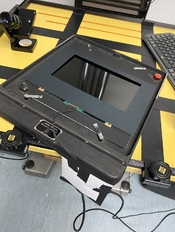
My initial plan is to use my enlarger exposure meter to determine an exposure time, and splitgrade print using filters to control contrast. So I’ve just set the ‘exposure’ time on the app to be minutes long and the enlarger timer will control the actual exposure for now. This enlarger (Durst L184) still uses the ‘unobtanium’ 11cm opal lamps - so leaving it on for extended periods is a bit risky re lamp life.
 

travelight

Member
Joined
Dec 1, 2024
Messages
43
Location
Australia
Format
Med. Format RF
Made the first print, exposure time was long ‘cos I half-sized the image rather than refocus the enlarger down to 8x10. However it printed fine with no filter, center correction did overcorrect a little in the highlights :wink:
 

Attachments

  • IMG_7793.jpeg
    IMG_7793.jpeg
    488.7 KB · Views: 76
  • IMG_7792.jpeg
    IMG_7792.jpeg
    270.8 KB · Views: 78

petersu

Member
Joined
Dec 22, 2024
Messages
2
Location
Guangdong, China
Format
ULarge Format
A quick update, I have been working on the software end of things and have many improvements. I changed the conversion algorithm and it is 100x faster. It can now create images that when displayed in sequence will allow for 10 and 12 bit (~4000) levels of grayscale. The exposure module steps through them automatically. The software works with a USB power strip to control the enlarger light source. The monitor is turned off so you initiate exposure with the space bar.

Hi, where can I download the software?
 

koraks

Moderator
Moderator
Joined
Nov 29, 2018
Messages
20,962
Location
Europe
Format
Multi Format
Hi, where can I download the software?

Welcome aboard, @petersu
You may want to check this message: https://www.photrio.com/forum/threads/diy-31-megapixel-enlarger.197305/page-7#post-2849864
Also, since you appear to be a representative of a supplier of the display components, @avandesande might want to know what your intentions with the software are. If it ends up in a commercial product or you're offering it directly to your customers, he may want to be aware of it.
 

travelight

Member
Joined
Dec 1, 2024
Messages
43
Location
Australia
Format
Med. Format RF
Glad to see your success. Are you using the exposure software? I've attached some luts to use with it, the ilfordbasecontrast is calibrated for Ilford WT with no filter and works for most things. The gamma file is for making negatives, there is more about this in the digital negative forum. There is a lut generator on the third tab of the sotware, just create the lut file and apply your curve in photoshop to make your own luts.

@avandesande I was thinking to make a lut for mgfb classic glossy on my L184 (incandescent bulb). I assumed I’d print a step wedge, measure some densities - then load a correction file - but I think I’m way off track. I see that there is a button that produces a gradient tif on the third tab - but I don’t know what that tif is based on, or is it just a linear 0-255 gradient? I’m unsure how that helps me make a lut? Do I just apply curves in PS to the gradient, export that as a new LUT tif, then print a step wedge using that new LUT and check if the step wedge looks right? I have a Stouffer step wedge - so I can contact print one with no filtration in order to make comparisons.
 
OP
OP

avandesande

Subscriber
Joined
Sep 7, 2002
Messages
1,343
Location
Albuquerque, NM
Format
Med Format Digital
The lut file is a tif with 255x255 (16 bit) grayscale values. You just apply your curve to it and reverence it when you import the file. If you look in the application resource folder you can examine the tif file used for the step wedge. It's a standard 21 step in 5% increments.
 

travelight

Member
Joined
Dec 1, 2024
Messages
43
Location
Australia
Format
Med. Format RF
The lut file is a tif with 255x255 (16 bit) grayscale values. You just apply your curve to it and reverence it when you import the file. If you look in the application resource folder you can examine the tif file used for the step wedge. It's a standard 21 step in 5% increments.

My resource folder only has a step wedge file in it, should there also another file?
So I guess what I’m not clear about, is how do I determine a curve? Is it just trial and error printing the step wedge with a variety of curves applied the the LUT file? If that’s it I’ll get into it, just wanted to know if there was a more deterministic way to do it with a densitometer.
I can also measure transmission through the lens using my rh-designs meter, it’ll set a zero at base plus fog then give density readings relative to that.
 
OP
OP

avandesande

Subscriber
Joined
Sep 7, 2002
Messages
1,343
Location
Albuquerque, NM
Format
Med Format Digital
Creating curves is a big subject and many methods. I used this tool QTR step wedge tool. I just exposed strips dried them in microwave and photographed the result. It's not the most fun thing to do. https://www.quadtonerip.com/html/QTRdownload.html. Also, I've used the ilford warmtone lut with ilford classic without any issue, it hasn't seemed worth the effort to make one specifically for it.
 

travelight

Member
Joined
Dec 1, 2024
Messages
43
Location
Australia
Format
Med. Format RF
Creating curves is a big subject and many methods. I used this tool QTR step wedge tool. I just exposed strips dried them in microwave and photographed the result. It's not the most fun thing to do. https://www.quadtonerip.com/html/QTRdownload.html. Also, I've used the ilford warmtone lut with ilford classic without any issue, it hasn't seemed worth the effort to make one specifically for it.

Ah ok - I got the quadtone software and was hoping I’d be able to use the densitometer - but I guess I can photograph the strips instead and import them to the tool.
 

travelight

Member
Joined
Dec 1, 2024
Messages
43
Location
Australia
Format
Med. Format RF
Creating curves is a big subject and many methods. I used this tool QTR step wedge tool. I just exposed strips dried them in microwave and photographed the result. It's not the most fun thing to do. https://www.quadtonerip.com/html/QTRdownload.html. Also, I've used the ilford warmtone lut with ilford classic without any issue, it hasn't seemed worth the effort to make one specifically for it.

Am I right in thinking that I can derive the endpoints of your curve by the k values at the top and bottom of that lut tif file? I’m finding I can’t get paper white and full black with the lut - so I’m thinking I’ll start off with a straight line between those two points and move them apart a bit until I get a full tonal range. Then I’ll see if I need an actual curve in between.
 
OP
OP

avandesande

Subscriber
Joined
Sep 7, 2002
Messages
1,343
Location
Albuquerque, NM
Format
Med Format Digital
Am I right in thinking that I can derive the endpoints of your curve by the k values at the top and bottom of that lut tif file? I’m finding I can’t get paper white and full black with the lut - so I’m thinking I’ll start off with a straight line between those two points and move them apart a bit until I get a full tonal range. Then I’ll see if I need an actual curve in between.

That's the way to do it. Establish your white and black points then find middle gray, then half of that. Keep in mind the panel I have is almost two years old now and for all I know the manufacturer has tweaked the contrast in the panels or driver. There is no specification for continuous tone and this is entirely 'off label' use of these panels.
 

travelight

Member
Joined
Dec 1, 2024
Messages
43
Location
Australia
Format
Med. Format RF
That suggests insufficient density, which would be odd. I suspect you may have a light leak problem that reduces contrast.

I think it’s just that my enlarger (Durst L184 condenser with 300w lamp) has lower effective grade than the OPs. I have the screen mounted in a spare carrier and masked off - I can print regular LF negatives in that setup just fine. I was also seeing relatively ‘flat’ midtones. I managed to get a better range by pulling the low end of the curve down to 15 from 30. But I’m still not entirely happy with the midtones - will play around a bit more.
Oddly I can’t find any way to use a regular densitometer in the QTR product - it’s input files are all device specific and looks like they want rgb values :/
Have either of you made a ‘printer profile’ for a paper for use in preview in photoshop? I have a reflectance/transmission densitometer and thought it might be interesting to see how that works.
 

travelight

Member
Joined
Dec 1, 2024
Messages
43
Location
Australia
Format
Med. Format RF
That's the way to do it. Establish your white and black points then find middle gray, then half of that. Keep in mind the panel I have is almost two years old now and for all I know the manufacturer has tweaked the contrast in the panels or driver. There is no specification for continuous tone and this is entirely 'off label' use of these panels.

Good advice, I freehand adjusted the curve using a specific image as the test, but I’m going to make a ‘fatter’ step wedge and try to be a little more scientific :wink:
 
OP
OP

avandesande

Subscriber
Joined
Sep 7, 2002
Messages
1,343
Location
Albuquerque, NM
Format
Med Format Digital
Now that you bring it up, I replaced the cold light with LED tubes, so I probably have more contrast on multigrade.
 

travelight

Member
Joined
Dec 1, 2024
Messages
43
Location
Australia
Format
Med. Format RF
Now that you bring it up, I replaced the cold light with LED tubes, so I probably have more contrast on multigrade.

Mines an incandescent Opal lamp, but yeah - quite probably I have less contrast with no filtration. I can of course use filters - but I lose 3/4stop or more of light and the exposure times get way too long. One day I’ll put a Heiland splitgrade lamp in and that will hopefully be significantly brighter and eliminate the need for filters altogether. Currently exposures look to be around 100-120s but that might change as I fine tune the highlight end of the curve I guess.
 

travelight

Member
Joined
Dec 1, 2024
Messages
43
Location
Australia
Format
Med. Format RF
That's the way to do it. Establish your white and black points then find middle gray, then half of that. Keep in mind the panel I have is almost two years old now and for all I know the manufacturer has tweaked the contrast in the panels or driver. There is no specification for continuous tone and this is entirely 'off label' use of these panels.

Apart from using the QTR tool, is there a reason to use a linear step wedge instead of a f-stop one. Density reducing in half stops from solid black. I think I should be able to calculate the k values back from 255. Will that work as I think, or am I going to head down a wrong path?
 

travelight

Member
Joined
Dec 1, 2024
Messages
43
Location
Australia
Format
Med. Format RF
OK, that explains it; you guys are comparing apples & oranges.
As in any process, establish white & black points first, ensure there's no fogging etc, then linearize.

I’m figuring it out better today - I realised that since you can’t go past zero density in the lcd - I need to determine the exposure that gives me a solid black at 0 density, then adjust the density of the highlights using the curve until I just get white at the other end. I made a condensed step wedge to make that easier to do with test strips.

So far it looks like the white end of the curve needs to be around 20% instead of 31%, but I’ll probably fine tune that a little once I dry my second test strip.
 

Attachments

  • IMG_7838.jpeg
    IMG_7838.jpeg
    440.2 KB · Views: 27

koraks

Moderator
Moderator
Joined
Nov 29, 2018
Messages
20,962
Location
Europe
Format
Multi Format
I need to determine the exposure that gives me a solid black at 0 density, then adjust the density of the highlights using the curve until I just get white at the other end.

That's one approach. The other is to take the full contrast range of the LCD as a starting point and select the contrast grade/filter that will give you a fill-scale print. Then use the curve to linearize the result. The advantage of this way is that it's less likely to result in posterization.
 

travelight

Member
Joined
Dec 1, 2024
Messages
43
Location
Australia
Format
Med. Format RF
That's one approach. The other is to take the full contrast range of the LCD as a starting point and select the contrast grade/filter that will give you a fill-scale print. Then use the curve to linearize the result. The advantage of this way is that it's less likely to result in posterization.

I want to try to fit it to a bare bulb because my exposure time is already 125s for an 8x10, putting on a 0-3 filter will blow that out to over 200s, more for a 4/5.
I think I have a pretty good curve now, once I determined an exposure for black, I eyeballed 21step wedge prints and adjusted the curve to get good separation.
I might do some fine adjustment at the top end of the highlights, or tweak the exposure a 1/12 of a stop. My test prints are coming out very nicely, will check once they dry.
This is the final curve shape - I ended up close to linear in the midtones/highlights to get better separation. iPhone screen grab of test print, way better than before :smile:
 

Attachments

  • IMG_7849.jpeg
    IMG_7849.jpeg
    382.3 KB · Views: 54
  • IMG_7850.jpeg
    IMG_7850.jpeg
    354 KB · Views: 52
  • IMG_7851.jpeg
    IMG_7851.jpeg
    406.6 KB · Views: 50

koraks

Moderator
Moderator
Joined
Nov 29, 2018
Messages
20,962
Location
Europe
Format
Multi Format
I'm surprised at your very long exposure times for this modest size print. But that's probably better discussed in a separate thread.
The curve looks like a good starting point. I have a feeling looking at the second print that there's some room for improvement especially in the shadows and midtones. Eyeballing is deceptive; it may work better to photograph or scan a step wedge and then plot the values in Excel.
 

travelight

Member
Joined
Dec 1, 2024
Messages
43
Location
Australia
Format
Med. Format RF
I'm surprised at your very long exposure times for this modest size print. But that's probably better discussed in a separate thread.
The curve looks like a good starting point. I have a feeling looking at the second print that there's some room for improvement especially in the shadows and midtones. Eyeballing is deceptive; it may work better to photograph or scan a step wedge and then plot the values in Excel.

It’s a fairly low powered lamp in a fairly huge 8x10 condenser enlarger. It’s faster for 8x10 negatives, I’m using a 240mm Componon-S lens at f11 (two stops down). I could try putting in a 5x7 condenser and using a 210mm lens which might give me a small improvement in time - but if I use the full screen it might vignette.
I’ll check the prints once they are dry, the iPhone pics are not very accurate. The annoying thing is that I have a reflectance densitometer, but the QTR tool doesn’t seem to have any capacity to use those readings. I guess I could try converting them to percentage of dmax? I’ve never computed curves like this before - just used it to calibrate my enlarging meters.
 

koraks

Moderator
Moderator
Joined
Nov 29, 2018
Messages
20,962
Location
Europe
Format
Multi Format
the QTR tool doesn’t seem to have any capacity to use those readings. I guess I could try converting them to percentage of dmax?

Yeah; QTR actually doesn't really care what kind of units it's being fed. However, since you're apparently applying the curve in PS or GIMP anyway, you might as well do the whole thing in Excel. The QTR tool seems nice, but it's kind of a black box and I've never had much luck with it; it tends to complain about the data a lot even when there's no clear reason for it. I try to steer clear from it most of the time.
 
Photrio.com contains affiliate links to products. We may receive a commission for purchases made through these links.
To read our full affiliate disclosure statement please click Here.

PHOTRIO PARTNERS EQUALLY FUNDING OUR COMMUNITY:


Ilford ADOX Freestyle Photographic Stearman Press Weldon Color Lab Blue Moon Camera & Machine
Top Bottom