-
Welcome to Photrio!Registration is fast and free. Join today to unlock search, see fewer ads, and access all forum features.Click here to sign up
You are using an out of date browser. It may not display this or other websites correctly.
You should upgrade or use an alternative browser.
You should upgrade or use an alternative browser.
DIY 31 Megapixel Enlarger
-
H
- Thread starter avandesande
- Start date


Recent Classifieds
-
For Sale Linhof 135mm Focusing Cam for Technika IV 4x5 45.00.
- Started by John Ackley
-
For Sale Darkroom Tool Set for Print or Sheet Film Handling
- Started by davela
-
For Sale Testrite CS-1 Copy Stand with Original Box
- Started by davela
-
For Sale Pentax branded camera straps (1 black w/ viewfinder cap, 1 grey)
- Started by Disconnekt
Forum statistics
Ethan Brossard
Member
do you have the 16k display? the files it takes need to be 1890x6230 pixels, which is an extremely odd resolution. the only way I've found to send the proper data for that is to add the resolution in the settings of my computer's Nvidia driver. another thing I discovered is that because display drivers want the pixel width to be divisible by 8, and 1890 is not, you need to configure it as an 1896x6230 display. However, this causes the 3 pixel columns to the right of center to go missing (the display is configured in two halves, and because the data is 6 pixels wider than the display, the three pixels at the beginning get cut out (that's not an issue because there's no pixels there), but the 3 pixels at the start of the second half also get cut out). to avoid losing the data in those 3 pixels (or rather 24 pixels because of how the display interprets them) you need to move the right half of the image over to the right by 3 pixels.
avandesande
Member
do you have the 16k display? the files it takes need to be 1890x6230 pixels, which is an extremely odd resolution. the only way I've found to send the proper data for that is to add the resolution in the settings of my computer's Nvidia driver. another thing I discovered is that because display drivers want the pixel width to be divisible by 8, and 1890 is not, you need to configure it as an 1896x6230 display. However, this causes the 3 pixel columns to the right of center to go missing (the display is configured in two halves, and because the data is 6 pixels wider than the display, the three pixels at the beginning get cut out (that's not an issue because there's no pixels there), but the 3 pixels at the start of the second half also get cut out). to avoid losing the data in those 3 pixels (or rather 24 pixels because of how the display interprets them) you need to move the right half of the image over to the right by 3 pixels.
This is the raspberry pi config:
hdmi_force_hotplug=1
display_rotate=0
hdmi_group=2
hdmi_mode=87
hvs_priority=0x32ff
framebuffer_depth=32
framebuffer_ignore_alpha=1
config_hdmi_boost=4
#gpu_mem=128
dtparam=i2c_arm=on
force_trubo=1
hdmi_pixel_freq_limit=400000000
hdmi_timings=1892 0 120 20 40 6230 0 32 4 28 0 0 0 20 0 260700000 0
max_framebuffer_width=15136
max_framebuffer_height=6230
framebuffer_width=1892
framebuffer_height=6230
dtparam=audio=on
disable_overscan=0
dtoverlay=pi3-miniuart-bt
hdmi_pixel_encoding=2
dtoverlay=vc4-fkms-v3d
#gpu_freq=300
#core_freq=400
over_voltage=4
#hdmi_enable_4kp60=1
dtoverlay=gpio-poweroff,active_low,gpiopin=23
travelight
Member
Went back and made a new curve for mgfb classic glossy from scratch. It’s looking pretty good, but I think I’ll try stretching the very end of the blacks so I can vary exposure a little to adjust highlights and still get maximum black.
Scanned print from the latest curve
Scanned print from the latest curve
Attachments
Looks nice!
I notice the shadows are relatively undifferentiated; is that also the case in the original and thus a deliberate artistic choice, or just a digital artefact of the version shown here? Just curious; not criticism. It just occurs to me because it seems to consistently be the case.
I notice the shadows are relatively undifferentiated; is that also the case in the original and thus a deliberate artistic choice, or just a digital artefact of the version shown here? Just curious; not criticism. It just occurs to me because it seems to consistently be the case.
travelight
Member
Looks nice!
I notice the shadows are relatively undifferentiated; is that also the case in the original and thus a deliberate artistic choice, or just a digital artefact of the version shown here? Just curious; not criticism. It just occurs to me because it seems to consistently be the case.
The scan lost a bit of shadow detail - I’m not an expert scanner, and it’s a little old. I think I may also have overexposed the prints slightly - judged the test pre-dry down.
OK, sounds plausible; for some reason, my Epson 4990 flatbed also has a habit of compressing shadows while leaving the rest of the tonal scale unaffected, so I recognize the issue. I figured the shadows might have been more open on the original print.
travelight
Member
Also - I don’t have much experience with digital printing in the first place - so it’s also possible that I’m adjusting the image on screen in a way that is compressing the blacks in the print. Got a bit of a learning curve to go through.Looks nice!
I notice the shadows are relatively undifferentiated; is that also the case in the original and thus a deliberate artistic choice, or just a digital artefact of the version shown here? Just curious; not criticism. It just occurs to me because it seems to consistently
Mines a 4890OK, sounds plausible; for some reason, my Epson 4990 flatbed also has a habit of compressing shadows while leaving the rest of the tonal scale unaffected, so I recognize the issue. I figured the shadows might have been more open on the original print.
If you're optimizing your curves visually, you may be shooting a moving target. It's easy to be led astray by idiosyncrasies of the images you're testing with, and the human eye is so gigantically non-linear and weirdly biased that it's darn difficult to build a good curve by just eyeballing images. It's tedious, but doing some step wedges and then taking some measurements off of those (you can use a scanner & photoshop for this part) and then constructing a curve in e.g. Excel is generally a more dependable and neutral approach that ends up working better overall.
travelight
Member
If you're optimizing your curves visually, you may be shooting a moving target. It's easy to be led astray by idiosyncrasies of the images you're testing with, and the human eye is so gigantically non-linear and weirdly biased that it's darn difficult to build a good curve by just eyeballing images. It's tedious, but doing some step wedges and then taking some measurements off of those (you can use a scanner & photoshop for this part) and then constructing a curve in e.g. Excel is generally a more dependable and neutral approach that ends up working better overall.
Yeah, this is the result of doing exactly that - used Wet Print’s web curve tool to make the adjustment curve (which does pretty much the same as excel I think). It’s better than the eyeball one I did before.
Graham06
Subscriber
- Joined
- Oct 31, 2006
- Messages
- 179
- Format
- Medium Format
A progress report:
I have my digital negative setup working well enough to start making test prints. I don't have that many minutes in the day to do darkroom stuff, and the sensible thing would be to work on one process at a time but Instead I have been experimenting with many:
- Continuous tone prints to Ilford Warmtone Glossy FB
- 1 bit depth images Floyd Steinberg dithered to MGWTFB
- 2x2 pixel 1 bit FS dithered images to AGFA Azura Vi 20 photopolymer plates https://www.ebay.com/itm/235775959908 and then inked and run through an etching press
-1 bit depth half tone images
I am struggling to get a linearisation curve that doesn't look bad and have been trying a few things, but more on that later. I am trying to use ChartThrob. I still haven't removed the protective films from the LCD, I just wiped my name off the film with isopropyl alchohol that the shipper wrote on it to protect himself from dishonest customers.
First, here is what I bought considering my preferences and all the helpful suggestions on this thread. I think I made good choices and I will eventually have something that works well for me (but I'm not there yet).
- A Dell 7050 Small Form Factor PC. A full computer: keyboard, mouse, monitor, and Windows 10, free shipping for $114 A lot more computer than a Raspberry Pi, and Windows means I can bootstrap with @avandesande's helpful software.
- An Nvidia 3050 SFF graphics card $196

- A power supply upgrade $20

Is possibly more computer than I need ( e.g. I am not sure hdmi 2.1 is a requirement), but this setup worked well for me without much fuss for me and I haven't seen subsequent configurations that I would have preferred.
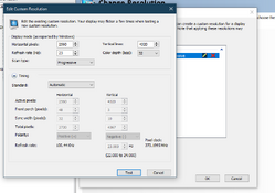
- The 10.1" 8k mono lcd from Sumaopai $264 Is probably the right choice for me. If I were going to buy two, perhaps the 7" 10k screen and the 14: 16k screens for contact printing would probably be the next step up. there is a 16" 8k screen but it is $550. If I show I have outgrown my current setup, probably what is available a year from now will be the best step up. Peter Su was helpful getting the display driver settings right, and would recommend him as a seller. Attached are the custom resolution settings I found for reference
My enlarger is a 4x5 Beseler 45mx which means I can't use all of my display, but the pixels are still small enough for me. I don't print larger than 8x10. I made an enclosure for the LCD using many layers of matt board glued together. That worked ok. Isn't yet finished enough to become plans for something 3d printed
One parameter of these displays that I didn't notice previously is how much light is let through. Mine lets through about 10% which is the highest I've seen. The smaller pixel displays let through about 4% This matters because large prints will take an annoyingly long time to print. Similar story for UV contact prints. I have been doing all my tests without multigrade filters.
How is everyone else coming along?
I have my digital negative setup working well enough to start making test prints. I don't have that many minutes in the day to do darkroom stuff, and the sensible thing would be to work on one process at a time but Instead I have been experimenting with many:
- Continuous tone prints to Ilford Warmtone Glossy FB
- 1 bit depth images Floyd Steinberg dithered to MGWTFB
- 2x2 pixel 1 bit FS dithered images to AGFA Azura Vi 20 photopolymer plates https://www.ebay.com/itm/235775959908 and then inked and run through an etching press
-1 bit depth half tone images
I am struggling to get a linearisation curve that doesn't look bad and have been trying a few things, but more on that later. I am trying to use ChartThrob. I still haven't removed the protective films from the LCD, I just wiped my name off the film with isopropyl alchohol that the shipper wrote on it to protect himself from dishonest customers.
First, here is what I bought considering my preferences and all the helpful suggestions on this thread. I think I made good choices and I will eventually have something that works well for me (but I'm not there yet).
- A Dell 7050 Small Form Factor PC. A full computer: keyboard, mouse, monitor, and Windows 10, free shipping for $114 A lot more computer than a Raspberry Pi, and Windows means I can bootstrap with @avandesande's helpful software.
- An Nvidia 3050 SFF graphics card $196
GIGABYTE GeForce RTX 3050 OC Low Profile 6G Graphics Card, 2x WINDFORCE Fans, 6G 889523041840| eBay
Find many great new & used options and get the best deals for GIGABYTE GeForce RTX 3050 OC Low Profile 6G Graphics Card, 2x WINDFORCE Fans, 6G at the best online prices at eBay! Free shipping for many products!
www.ebay.com
- A power supply upgrade $20
Is possibly more computer than I need ( e.g. I am not sure hdmi 2.1 is a requirement), but this setup worked well for me without much fuss for me and I haven't seen subsequent configurations that I would have preferred.
- The 10.1" 8k mono lcd from Sumaopai $264 Is probably the right choice for me. If I were going to buy two, perhaps the 7" 10k screen and the 14: 16k screens for contact printing would probably be the next step up. there is a 16" 8k screen but it is $550. If I show I have outgrown my current setup, probably what is available a year from now will be the best step up. Peter Su was helpful getting the display driver settings right, and would recommend him as a seller. Attached are the custom resolution settings I found for reference
My enlarger is a 4x5 Beseler 45mx which means I can't use all of my display, but the pixels are still small enough for me. I don't print larger than 8x10. I made an enclosure for the LCD using many layers of matt board glued together. That worked ok. Isn't yet finished enough to become plans for something 3d printed
One parameter of these displays that I didn't notice previously is how much light is let through. Mine lets through about 10% which is the highest I've seen. The smaller pixel displays let through about 4% This matters because large prints will take an annoyingly long time to print. Similar story for UV contact prints. I have been doing all my tests without multigrade filters.
How is everyone else coming along?
Attachments
Last edited:
Ethan Brossard
Member
I've been making good progress with the 16k display. I currently have it running on a raspberry pi, and optimized the program so it runs much more efficiently than it did on the beafy windows computer I was using to run it previously. Raspberry pi 4b is what was recommended, but I got it to work on a 5, which has more computing power.
Also a word of warning to you all- don't leave your display on when you aren't using it. I left mine on overnight and the next day had issues with image persistence (the desktop pattern staying on the screen even when I wrote other images to it). A few hours with an alternating white/black screen gif and it went away, but it was annoying.
Also a word of warning to you all- don't leave your display on when you aren't using it. I left mine on overnight and the next day had issues with image persistence (the desktop pattern staying on the screen even when I wrote other images to it). A few hours with an alternating white/black screen gif and it went away, but it was annoying.
Ethan Brossard
Member
A progress report:
I have my digital negative setup working well enough to start making test prints. I don't have that many minutes in the day to do darkroom stuff, and the sensible thing would be to work on one process at a time but Instead I have been experimenting with many:
- Continuous tone prints to Ilford Warmtone Glossy FB
- 1 bit depth images Floyd Steinberg dithered to MGWTFB
- 2x2 pixel 1 bit FS dithered images to AGFA Azura Vi 20 photopolymer plates https://www.ebay.com/itm/235775959908 and then inked and run through an etching press
-1 bit depth half tone images
I am struggling to get a linearisation curve that doesn't look bad and have been trying a few things, but more on that later. I am trying to use ChartThrob. I still haven't removed the protective films from the LCD, I just wiped my name off the film with isopropyl alchohol that the shipper wrote on it to protect himself from dishonest customers.
First, here is what I bought considering my preferences and all the helpful suggestions on this thread. I think I made good choices and I will eventually have something that works well for me (but I'm not there yet).
- A Dell 7050 Small Form Factor PC. A full computer: keyboard, mouse, monitor, and Windows 10, free shipping for $114 A lot more computer than a Raspberry Pi, and Windows means I can bootstrap with @avandesande's helpful software.
- An Nvidia 3050 SFF graphics card $196
GIGABYTE GeForce RTX 3050 OC Low Profile 6G Graphics Card, 2x WINDFORCE Fans, 6G 889523041840| eBay
Find many great new & used options and get the best deals for GIGABYTE GeForce RTX 3050 OC Low Profile 6G Graphics Card, 2x WINDFORCE Fans, 6G at the best online prices at eBay! Free shipping for many products!www.ebay.com
- A power supply upgrade $20
Is possibly more computer than I need ( e.g. I am not sure hdmi 2.1 is a requirement), but this setup worked well for me without much fuss for me and I haven't seen subsequent configurations that I would have preferred.
- The 10.1" 8k mono lcd from Sumaopai $264 Is probably the right choice for me. If I were going to buy two, perhaps the 7" 10k screen and the 14: 16k screens for contact printing would probably be the next step up. there is a 16" 8k screen but it is $550. If I show I have outgrown my current setup, probably what is available a year from now will be the best step up. Peter Su was helpful getting the display driver settings right, and would recommend him as a seller.
My enlarger is a 4x5 Beseler 45mx which means I can't use all of my display, but the pixels are still small enough for me. I don't print larger than 8x10. I made an enclosure for the LCD using many layers of matt board glued together. That worked ok. Isn't yet finished enough to become plans for something 3d printed
One parameter of these displays that I didn't notice previously is how much light is let through. Mine lets through about 10% which is the highest I've seen. The smaller pixel displays let through about 4% This matters because large prints will take an annoyingly long time to print. Similar story for UV contact prints. I have been doing all my tests without multigrade filters.
How is everyone else coming along?
Do you know what the refresh rate of your display is? the 16k display is only 20hz, and so does not require the bitrate of hdmi 2.1. A raspberry pi 5 is more than enough to drive it
travelight
Member
A progress report:
I have my digital negative setup working well enough to start making test prints. I don't have that many minutes in the day to do darkroom stuff, and the sensible thing would be to work on one process at a time but Instead I have been experimenting with many:
- Continuous tone prints to Ilford Warmtone Glossy FB
- 1 bit depth images Floyd Steinberg dithered to MGWTFB
- 2x2 pixel 1 bit FS dithered images to AGFA Azura Vi 20 photopolymer plates https://www.ebay.com/itm/235775959908 and then inked and run through an etching press
-1 bit depth half tone images
I am struggling to get a linearisation curve that doesn't look bad and have been trying a few things, but more on that later. I am trying to use ChartThrob. I still haven't removed the protective films from the LCD, I just wiped my name off the film with isopropyl alchohol that the shipper wrote on it to protect himself from dishonest customers.
First, here is what I bought considering my preferences and all the helpful suggestions on this thread. I think I made good choices and I will eventually have something that works well for me (but I'm not there yet).
- A Dell 7050 Small Form Factor PC. A full computer: keyboard, mouse, monitor, and Windows 10, free shipping for $114 A lot more computer than a Raspberry Pi, and Windows means I can bootstrap with @avandesande's helpful software.
- An Nvidia 3050 SFF graphics card $196
GIGABYTE GeForce RTX 3050 OC Low Profile 6G Graphics Card, 2x WINDFORCE Fans, 6G 889523041840| eBay
Find many great new & used options and get the best deals for GIGABYTE GeForce RTX 3050 OC Low Profile 6G Graphics Card, 2x WINDFORCE Fans, 6G at the best online prices at eBay! Free shipping for many products!www.ebay.com
- A power supply upgrade $20
Is possibly more computer than I need ( e.g. I am not sure hdmi 2.1 is a requirement), but this setup worked well for me without much fuss for me and I haven't seen subsequent configurations that I would have preferred.
- The 10.1" 8k mono lcd from Sumaopai $264 Is probably the right choice for me. If I were going to buy two, perhaps the 7" 10k screen and the 14: 16k screens for contact printing would probably be the next step up. there is a 16" 8k screen but it is $550. If I show I have outgrown my current setup, probably what is available a year from now will be the best step up. Peter Su was helpful getting the display driver settings right, and would recommend him as a seller.
My enlarger is a 4x5 Beseler 45mx which means I can't use all of my display, but the pixels are still small enough for me. I don't print larger than 8x10. I made an enclosure for the LCD using many layers of matt board glued together. That worked ok. Isn't yet finished enough to become plans for something 3d printed
One parameter of these displays that I didn't notice previously is how much light is let through. Mine lets through about 10% which is the highest I've seen. The smaller pixel displays let through about 4% This matters because large prints will take an annoyingly long time to print. Similar story for UV contact prints. I have been doing all my tests without multigrade filters.
How is everyone else coming along?
My setup is working pretty well. I also have the 10.1” 8K display, mounted in the neg carrier for my L184 8x10 enlarger.
I finally managed to make a decent curve by scanning the step wedge print and entering the lab values into the SCTV Curve Creator tool here: https://thewetprint.com/resources/
In my case I had both ends of the strip blocking for at least two steps (paper white, max black) which I think is necessary. I made my curve with no filtration so as to minimise exposure times, which are long on my enlarger.
My next moves will be to make a more permanent mount for the display in the negative holder, and to calibrate my RH Designs timer to allow me to take exposure readings directly. (Also very interested in how the 16k screen is going as that would allow larger prints in future).
Graham06
Subscriber
- Joined
- Oct 31, 2006
- Messages
- 179
- Format
- Medium Format
It is 23hz or 22hz, I attached a screenshot I took when I found it to my post above. I can't double check nowDo you know what the refresh rate of your display is? the 16k display is only 20hz, and so does not require the bitrate of hdmi 2.1. A raspberry pi 5 is more than enough to drive it
because I can't find a way to view the in-use custom resolution with the nvidia display utility. I know I don't have the cheapest setup that works well. I might not even have needed the Nvidia 3050 card, but I read that @avandesande broke a display driving it incorrectly with an intel on board driver and I didn't want the fuss.
@Andrew O'Neill [edit: corrected name] and others might be interested in your display software. I recall he said his Pi 4 takes a second to display an image. Think he is using OpenCV
I like and appreciate @avandesande 's display software, but if he doesn't want to release the source, I'll eventually write my own. I'm enjoying just taking the path of least resistance.
Last edited:
Graham06
Subscriber
- Joined
- Oct 31, 2006
- Messages
- 179
- Format
- Medium Format
You will need to solve the long exposure problem. Big prints mean less light and the 16k screen has 4% transmission ( I think) compared to ours which has 10% transmission. I don't print big, but I wonder how big we can go with our setup.. I made my curve with no filtration so as to minimise exposure times, which are long on my enlarger.
...(Also very interested in how the 16k screen is going as that would allow larger prints in future).
Ethan Brossard
Member
You will need to solve the long exposure problem. Big prints mean less light and the 16k screen has 4% transmission ( I think) compared to ours which has 10% transmission. I don't print big, but I wonder how big we can go with our setup.
My exposure time with the 16k display for a 2x enlargement at f/5.6 with a 250 watt bulb (diffusion enlarger) is 16 seconds. A 4x print (around 20"x30") would take 1 minute, an 8x print 4 minutes. However, an 8x print would require me to switch to my bigger enlarger, which is also much brighter
travelight
Member
My exposure time with the 16k display for a 2x enlargement at f/5.6 with a 250 watt bulb (diffusion enlarger) is 16 seconds. A 4x print (around 20"x30") would take 1 minute, an 8x print 4 minutes. However, an 8x print would require me to switch to my bigger enlarger, which is also much brighter
My L184 currently has a 200W incandescent opal lamp and the 10x10” condensers - and my exposure times for 8x10 prints with a 240mm f5.6 Componon-s lens using pretty much the full screen size are up around 30s at f8.
f8 is probably ok sharpness wise, but I’d rather be using f11 - so if I went to a darker screen I’d almost certainly have to figure out a brighter light source. That’s with no filtration - if I want to fine tune with say some splitgrade contrast filters the time goes up by 2-4x.
Last edited:
Graham06
Subscriber
- Joined
- Oct 31, 2006
- Messages
- 179
- Format
- Medium Format
I think we are doing the right thing with our no-filter settings. I also suspect that the tone curve of no-filter is not the same as any filter grade or any splitgrade combination. But! now that we have a digital negative, I think splitgrade has nothing more to offer. Splitgrade was certainly helpful in getting a good print, and I think that a digital negative won't magically enable us to get an ideal print first try.if I want to fine tune with say some splitgrade contrast filters the time goes up by 2-4x.
One of the things I want to explore is test prints. We are no longer limited to a 5 step test strip. I imagine a test print with a step wedge, a thumbnail of the full image, full size patches of interesting areas, and strips with various degrees of tone adjustment: stepped adjustments to the last 10% of shadows or 5% or 20% etc.
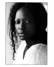
I think the workflow will be a hybrid combintation of the digital workflow (photoshop etc) and the analogue one. First you get close in Photoshop, and then print a test print with steps for the things that are known to vary. Then you apply those and see what a full size print look like. Maybe there is a round where you make adjustments in photoshop while holding a dried full size print that isn't quite right. That fantastic headshot portrait you posted in this thread is a perfect example: the shadows have subtle details that don't translate between digital and analogue versions. With hindsight, what workflow would have gotten you your final best effort with only 1 or 2 tests before the final print?
travelight
Member
Just installed a 300w lamp and now I have 26s 8x10 exposures at f11
With the new curve, and a single 1/4 stop test strip I’m getting to a good print for a given enlargement (all prints can use the same time if the enlargement doesn’t change).
Excellent shadow detail.
With the new curve, and a single 1/4 stop test strip I’m getting to a good print for a given enlargement (all prints can use the same time if the enlargement doesn’t change).
Excellent shadow detail.
Attachments

- travelight
- Deleted
- Reason: Duplicate post
Ethan Brossard
Member
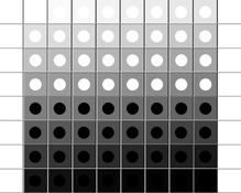
This might be useful for you all. When making a print I first use a blank frame to determine the time needed for maximum black. once I have that time I print this image which goes from 0% to 100% black with dots of black and white. This allows me to create a photoshop curve which limits the image to the points where it produces maximum black and maximum white on the paper, without needing to test each image.
Attachments
Graham06
Subscriber
- Joined
- Oct 31, 2006
- Messages
- 179
- Format
- Medium Format
NiceJust installed a 300w lamp and now I have 26s 8x10 exposures at f11
With the new curve, and a single 1/4 stop test strip I’m getting to a good print for a given enlargement (all prints can use the same time if the enlargement doesn’t change).
Excellent shadow detail.
My beseler 45mx is maxed out at 150W. I use an Ilford em10 meter to change the enlargement and keep the exposure the sametravelight
Member
Theoretically I can go up to 1000w… but I’d need to find a 1000w 11cm opal lamp (virtually impossible) and pay for it (>$500AUD plus shipping).. and I’d have to install a cooling fan.
If I want to go any brighter and keep the condensers it will have to be a high-power LED alternative.
If I want to go any brighter and keep the condensers it will have to be a high-power LED alternative.
travelight
Member
This might be useful for you all. When making a print I first use a blank frame to determine the time needed for maximum black. once I have that time I print this image which goes from 0% to 100% black with dots of black and white. This allows me to create a photoshop curve which limits the image to the points where it produces maximum black and maximum white on the paper, without needing to test each image.
That’s pretty much how I made the curve I use now - except I used a 21step wedge of 5% density increase. The curve works fine at any enlargement in terms of full contrast range, but I don’t yet have a quick way of determining the correct exposure at any given enlargement without doing a test strip. I’m thinking of making a special calibration on my RH Designs timer to be able to take a reading from a blank screen, set it to maximum black and then read off the correct exposure. It should work pretty well I think - although it’s not really the usual way of using the timer.
Graham06
Subscriber
- Joined
- Oct 31, 2006
- Messages
- 179
- Format
- Medium Format
I am hoping to avoid test strips too but I think it will be hard. You have to pay attention to developer age, how many hours ago it was mixed, how many prints have been made, developer temperature etc. You can reduce variability by developing for 2+ minutes and using 'factorial development' ( 4x (or whatever) time for the image to first appear in the tray)That’s pretty much how I made the curve I use now - except I used a 21step wedge of 5% density increase. The curve works fine at any enlargement in terms of full contrast range, but I don’t yet have a quick way of determining the correct exposure at any given enlargement without doing a test strip. I’m thinking of making a special calibration on my RH Designs timer to be able to take a reading from a blank screen, set it to maximum black and then read off the correct exposure. It should work pretty well I think - although it’s not really the usual way of using the timer.
Was also thinking of adding a calibration strip ( e.g. a grey ramp and some key black and white circles like Ethan posted) next to candidate final prints that you could cut off later or hide under a matt frame if you framed it. That way if you don't get it exactly right first try, you at least know more precisely where to go next.
I have been trying to make a digital test strip, and it is not trivial. The 2.2 gamma adjustment that is built into the display makes things complicated. My next test is to make ChartThrob correction curves for various exposures around a +0 linearised print. This will be needed to add exposure time units to the calibration strip.
Alternatively once you have a calibration strip, you just always quickly print one to a small scrap, and read a correction right out of the stop bath.
| Photrio.com contains affiliate links to products. We may receive a commission for purchases made through these links. To read our full affiliate disclosure statement please click Here. |
PHOTRIO PARTNERS EQUALLY FUNDING OUR COMMUNITY:  |