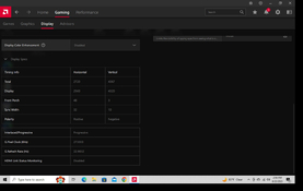
DIY 31 Megapixel Enlarger

Sparrow.jpg

A
Sparrow.jpg

  • 1
  • 0
  • 40
Orlovka river valley

A
Orlovka river valley

  • 4
  • 0
  • 90
Norfolk coast - 2

A
Norfolk coast - 2

  • 5
  • 1
  • 84
In the Vondelpark

A
In the Vondelpark

  • 4
  • 2
  • 163
Cascade

A
Cascade

  • sly
  • May 22, 2025
  • 9
  • 6
  • 140

Recent Classifieds

Forum statistics

Threads
197,840
Messages
2,765,431
Members
99,487
Latest member
Nigel Dear
Recent bookmarks
0

Graham06

Member
Joined
Oct 31, 2006
Messages
125
Format
Medium Format
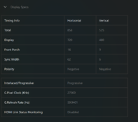
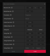
Making some small steps with '16k' lcd. For starters, it's not really 16k. its resolution is 11,154x6,230 adjusting for the rectangular pixels which is really slightly under 12k. However, that is enough to fully resolve the GFX50r output or a 60mp full frame camera. Still a ton of work to do to get this in the darkroom... I am going to incorporate resize into the application itself (a complex subject) and look into GPU acceleration. Probably several months out. The photo is a image that has been bitmapped to 3 bit. Dimensions are 11203 x 6192 and 1400 x 6192 after the mapping. I promised myself I wouldn't work on this but like the story of the scorpion and the frog I can't resist, not sure if I am the scorpion or the frog!

How many frames per second can you show without tearing artifacts etc? Won't you need to show 32 frames to get another 5 bits of colour depth? How many bits of colour depth to see subtle tones and avoid banding in skies etc. You can use floyd steinberg dithering for the remaining depth. And if you fs dither each frame, each frame will have its own dither pattern which would further reduce visible noise. And then there's how to choose the 32 frames to minimise light bleeding. And light bleed compensation/deconvolution.

When you add everything together it goes from a routine bit of code to a fun computer problem ( though perhaps you do each step separately and it isn't hard)

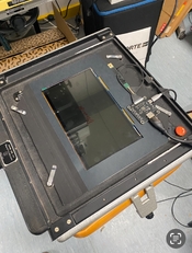
I'm on the verge of clicking the purchase button on the parts to make something. I'm a programmer but don't really enjoy messing with electronics. I have a beseler 45mx with those round holders and have been experimenting with etching copper plates with pcb photoresist film for photogravure. I found a beseler film holder on one of those 3d printing sites, and I imagine it won't be too hard to modify the model to hold a LCD. I'd use to print digital negatives, and contact print pcb film covered plates

I'm not sure I can make a single purchase serve both purposes: if I want to contact print, I should get a 10.1" lcd. if I want a digital 4x5 negative, I should get that 6.9" 9k one
 

koraks

Moderator
Moderator
Joined
Nov 29, 2018
Messages
21,315
Location
Europe
Format
Multi Format
How many frames per second can you show without tearing artifacts etc?

For printing, it doesn't have to go fast, does it? You can modulate the light source in tandem. It'll likely be easier to do that if you need to handle any timing issues than trying to fix that on the display side. And aren't these displays 8bit anyway? That would make things a lot less complicated for most printing that involves continuous tone. It'll be different if you want/need to do halftones. For your photogravure, this is a relevant issue. But then you're stuck with 1 bit pixels anyway.

I have a beseler 45mx with those round holders and have been experimenting with etching copper plates with pcb photoresist film for photogravure.

I've thought about that, but I had sold off the etching press before I started making PCB's in earnest. I now use a liquid/paste resist for PCBs and contact print them on the same setup as my carbon transfer prints. The main difference is that the PCB resist is very, very fast (solder mask is very slow, by contrast).
 

Graham06

Member
Joined
Oct 31, 2006
Messages
125
Format
Medium Format
For printing, it doesn't have to go fast, does it?
avandesande said his image was 3 bits deep. Looking at the specs online for the 12k 10.1 screen it seems the display speed is around 20hz (perhaps the answer to my question), so it will take more than a second to display all 32 frames, which starts to become a problem if your exposure time is short, and the light cuts out mid cycle
 

koraks

Moderator
Moderator
Joined
Nov 29, 2018
Messages
21,315
Location
Europe
Format
Multi Format
avandesande said his image was 3 bits deep. Looking at the specs online for the 12k 10.1 screen it seems the display speed is around 20hz

I think you're confusing a couple of things here. The 3-bit story is compressing three monochrome pixels into a single RGB pixel.
This in turn is unrelated to display speed since as I said you can pulse the light source of response time of the display is a problem. However, even at a sluggish refresh rate of 20Hz you're still working with 50ms exposures, which is an order of magnitude faster than what you generally print with on silver gelatin.
So no, I don't see the problem you're pointing out, and even if it existed, it would be easy to work around by switching the light source.
 

Graham06

Member
Joined
Oct 31, 2006
Messages
125
Format
Medium Format
I think you're confusing a couple of things here. The 3-bit story is compressing three monochrome pixels into a single RGB pixel.
This in turn is unrelated to display speed since as I said you can pulse the light source of response time of the display is a problem. However, even at a sluggish refresh rate of 20Hz you're still working with 50ms exposures, which is an order of magnitude faster than what you generally print with on silver gelatin.
So no, I don't see the problem you're pointing out, and even if it existed, it would be easy to work around by switching the light source.
See post #159 and #160. The 16k screen is 3 bit (8 levels), but the 8k screen is 8 bit (256 levels) All are mono, so require 3x less data. So supposedly these 16k screens are not the same, and if you do nothing more, you'll have the shitty image in post #174. But there are two very achievable improvements: add another 32 frames to get another 5 bits of colour depth, and use floyd steinberg dithering to correct colour error in neighbouring pixels. We are waiting with interest to see the progress the OP and others make. I am sure they will at least almost succeed.

Re modulating the light source in sync with the display: if I understand your idea, it is to choose the light level for each 50ms frame. If you have that ability, you can get the extra bit depth in 5 frames ( base 2) instead of 32 (base 1). I am sure it is possible 'cos that's how rgb LEDs work, but the electronics skill required is beyond my ability.

With a 20Hz display, and 32 frames, you have a 1.5s exposure cycle, and I imagine you'd have to keep exposures over 10s to avoid artifacts (which I realise I can do 'cos my Beseler enlarger has a 'resistrol' dimmer I can use. My undimmable UV lamp is wired to my ceiling, but I can put an aperture over it if I need to which is within my electronics ability)

For the dithering, you can use the wonderful command line tool ImageMagick. It has loads of options ( chatgpt will save you hours of documentation reading even if it is almost always slightly to very wrong) It can scale the image to adjust for rectangular pixels too.

I actually think it will be a challenge to go from 'almost works' to 'amazing' The things we like about a photo print are often very subtle, and a tiny little line, barely visible banding, slight fuzziness or slightly uneven tones will make us throw a print attempt in the bin. I really want to pick a 12k or 16k screen, but I worry that rectangular pixels will lead to unfixable artifacts
 

koraks

Moderator
Moderator
Joined
Nov 29, 2018
Messages
21,315
Location
Europe
Format
Multi Format
if I understand your idea, it is to choose the light level for each 50ms frame.

You're not bound to the 50ms timeframe. You've got all the time in the world of you turn off the light source in between exposures. With an LED light this works for sure, with halogen/tungsten it depends a bit, but should work in principle just as well.
I don't see the purpose personally in hanging on to stuff like a resistrol while at the same time using a fancy LCD. If you can hack an LCD into an enlarger, you can hack a programmable LED source into it just as well.
 

AndrewBurns

Member
Joined
Jul 12, 2019
Messages
197
Location
Auckland, New Zealand
Format
35mm
I'm not quite sure what the desire to use the super-high resolution displays with rectangular pixels is in the first place? From my calcs a 10" 8k resolution screen will give you >300 dpi on a 16x12" print size which is plenty for me. I suppose if you want to go to very large prints it might make sense.
 

Graham06

Member
Joined
Oct 31, 2006
Messages
125
Format
Medium Format
You're not bound to the 50ms time frame. You've got all the time in the world of you turn off the light source in between exposures.
Then I don't think I am understanding what you are proposing. The light source turns all off or all to a certain level at some time. The lcd changes 20 times a second or 100 times in a short 5s exposure (assuming 5s min exp as a design constraint) If you choose 5 levels (1,0.5,0.25,0.125,0.06) you still have to sync to a time resolution of 1s which you could do by hand with practice. But it feels like a hassle.

Avandesand's technique leaves the light source on full the whole time. I haven't looked at his code, but I expect he makes new frames by adding the residual error from the previous frame. You'll have >10 bits of colour depth after only a few seconds.
I don't see the purpose personally in hanging on to stuff like a resistrol while at the same time using a fancy LCD.
For me, my limited resource is enthusiasm. I don't enjoy darkroom work all that much, so I am trying to minimize the effort required to get a beautiful print that I am proud of. Different techniques each add their own special character that adds something to a print that I didn't plan ( e.g. copper plate etchings have something special when you see them in person and hold one. Same for carbon prints I believe, though I've never seen one ) For me, my life skills are in programming, and some time as an amateur photographer. I am at beginner level for electronics, and don't enjoy the time and experience required to learn. The more skill you have the more you can get out for the effort provided.

AndrewBurns' comment about dpi makes me realize I will be happy with a 10"8k screen. I can put it in a 4x5 enlarger and just print from the center and still have fairly large prints at >300dpi. I never make very large prints anyway. That way I follow the well trodden path.
 

AndrewBurns

Member
Joined
Jul 12, 2019
Messages
197
Location
Auckland, New Zealand
Format
35mm
Then I don't think I am understanding what you are proposing. The light source turns all off or all to a certain level at some time. The lcd changes 20 times a second or 100 times in a short 5s exposure (assuming 5s min exp as a design constraint) If you choose 5 levels (1,0.5,0.25,0.125,0.06) you still have to sync to a time resolution of 1s which you could do by hand with practice. But it feels like a hassle.

Avandesand's technique leaves the light source on full the whole time. I haven't looked at his code, but I expect he makes new frames by adding the residual error from the previous frame. You'll have >10 bits of colour depth after only a few seconds.

I think the idea is that you should easily be able to turn the light source on and off quickly and at will. So you could display a static image on the screen, flash the light source for 0.5 seconds, and then refresh the LCD while the light is turned off. With my LCD-based UV contact printing rig it actually takes about 1 second for the image to display full-screen because my raspbery pi is kinda slow, so I just leave the UV LED off until the image is properly displayed and then turn it on.
 

Graham06

Member
Joined
Oct 31, 2006
Messages
125
Format
Medium Format
I think the idea is that you should easily be able to turn the light source on and off quickly and at will. So you could display a static image on the screen, flash the light source for 0.5 seconds, and then refresh the LCD while the light is turned off. With my LCD-based UV contact printing rig it actually takes about 1 second for the image to display full-screen because my raspbery pi is kinda slow, so I just leave the UV LED off until the image is properly displayed and then turn it on.
Oh, I see. You make a number of exposures, each half/double the length of the previous one. Each frame you add, adds an extra bit of colour depth. No fancy syncing required.
 

travelight

Member
Joined
Dec 1, 2024
Messages
43
Location
Australia
Format
Med. Format RF
I've got the 10.1/8k screen, and I picked up a Minisforum UM760 'Slim' pc with AMD Radeon 760m card, which supports hdmi2.1 - however the screen is only detected as a generic 720x480 PnP monitor.. what a I missing?
I saw a similar pc suggested, but only just noticed a later comment about AMD drivers, I hope I haven't bought the wrong unit :/
 

koraks

Moderator
Moderator
Joined
Nov 29, 2018
Messages
21,315
Location
Europe
Format
Multi Format
Minisforum UM760 'Slim' pc with AMD Radeon 760m card

What operating system are you running on it?
What driver do you have installed for the Radeon graphics card?
Keep in mind you may need to install/update a display driver whenever the card happens to be newer than the drivers the operating system comes with. Due to the rapid introduction of new hardware, it's common for an operating system to come with drivers that don't work well with newer hardware.
 
OP
OP

avandesande

Subscriber
Joined
Sep 7, 2002
Messages
1,345
Location
Albuquerque, NM
Format
Med Format Digital
You will need to make sure the Amd software is installed and set manually. It is frustrating to use but if you hunt enough you can find the settings and set them.
 

Attachments

  • graphics settings copy.jpg
    graphics settings copy.jpg
    92.5 KB · Views: 38

travelight

Member
Joined
Dec 1, 2024
Messages
43
Location
Australia
Format
Med. Format RF
@avandesande I figured out how to install the AMD software, and found where to create a custom resolution.. but there are a few extra settings there that i don't see on your example. I'm a little wary about frying the device if I get it wrong.

..also this is slowed down a bit as i forgot id need a keyboard so I'm using the accessibility onscreen one with a mouse

win11, latest drivers
 

Attachments

  • Screenshot 2024-12-18 012840.png
    Screenshot 2024-12-18 012840.png
    197.7 KB · Views: 27
Last edited:
OP
OP

avandesande

Subscriber
Joined
Sep 7, 2002
Messages
1,345
Location
Albuquerque, NM
Format
Med Format Digital
This from the manufacturer, the nvidia settings translate 1:1
 

Attachments

  • nvidiasettings.jpg
    nvidiasettings.jpg
    322.5 KB · Views: 42
OP
OP

avandesande

Subscriber
Joined
Sep 7, 2002
Messages
1,345
Location
Albuquerque, NM
Format
Med Format Digital
Sorry, i'm not sure how to interpret/map those to my settings. do you mean they are in identical positions?

I just figured out from looking at it. If you can wait later today I will hook up LCD screen to my NVIDIA machine and get you a english screen shot.
 

travelight

Member
Joined
Dec 1, 2024
Messages
43
Location
Australia
Format
Med. Format RF
does this look correct? if i change timing standard to 'CVT' it resets the timing info so i left it on manual
 

Attachments

  • Screenshot 2024-12-18 015221.png
    Screenshot 2024-12-18 015221.png
    185.5 KB · Views: 19

travelight

Member
Joined
Dec 1, 2024
Messages
43
Location
Australia
Format
Med. Format RF
..actually its 2am here, i probably should leave this for tomorrow. if you do get an English screenshot that would be great. I tried creating the profile and it refused as not compatible with the device... so there may be something else i need to change first?
this is what is currently set
 

Attachments

  • Screenshot 2024-12-18 020924.png
    Screenshot 2024-12-18 020924.png
    140.5 KB · Views: 16
Last edited:

travelight

Member
Joined
Dec 1, 2024
Messages
43
Location
Australia
Format
Med. Format RF
refuses to allow me to create custom resolution like this, error incompatible with display :/
 

Attachments

  • Screenshot 2024-12-18 021838.png
    Screenshot 2024-12-18 021838.png
    216.3 KB · Views: 27

travelight

Member
Joined
Dec 1, 2024
Messages
43
Location
Australia
Format
Med. Format RF
Well, I appear to have got it working - I downloaded a tool called CRU and used that to add a DisplayID extension block with the custom resolution, along with some other tweaks. When I went back into the AMD tool, the display was now recognized as "DDC Display - HDMI", and I could create the custom resolution in the AMD tool, and now its applied I see an image on the screen.
 
OP
OP

avandesande

Subscriber
Joined
Sep 7, 2002
Messages
1,345
Location
Albuquerque, NM
Format
Med Format Digital
I was just working on getting the screenshot posted for you with nvidia settings. Glad to hear it is working!
 

Attachments

  • nvidia_settings.jpg
    nvidia_settings.jpg
    86.9 KB · Views: 34

travelight

Member
Joined
Dec 1, 2024
Messages
43
Location
Australia
Format
Med. Format RF
Installed into a temporary mask in the pin-register carrier for my L184, and projecting a nice crisp negative. I can pretty easily focus on the grid with my grain focuser at this enlargement - so it’s probably a bit too big. Will try making some 12x16 prints tomorrow :smile:
Thanks for the assistance, and for the wonderful software.
I ended up rotating the mask 180’ and taping the driver board on front of the carrier - there’s a small felt strip at the front that allows the wire to pass through. As shown in the pic, there wasn’t clearance for the bulkier cables.
 

Attachments

  • IMG_7787.jpeg
    IMG_7787.jpeg
    542.3 KB · Views: 62
  • IMG_7788.jpeg
    IMG_7788.jpeg
    535.8 KB · Views: 56
OP
OP

avandesande

Subscriber
Joined
Sep 7, 2002
Messages
1,345
Location
Albuquerque, NM
Format
Med Format Digital
Glad to see your success. Are you using the exposure software? I've attached some luts to use with it, the ilfordbasecontrast is calibrated for Ilford WT with no filter and works for most things. The gamma file is for making negatives, there is more about this in the digital negative forum. There is a lut generator on the third tab of the sotware, just create the lut file and apply your curve in photoshop to make your own luts.
 

Attachments

  • luts.zip
    111.7 KB · Views: 25

travelight

Member
Joined
Dec 1, 2024
Messages
43
Location
Australia
Format
Med. Format RF
Glad to see your success. Are you using the exposure software? I've attached some luts to use with it, the ilfordbasecontrast is calibrated for Ilford WT with no filter and works for most things. The gamma file is for making negatives, there is more about this in the digital negative forum. There is a lut generator on the third tab of the sotware, just create the lut file and apply your curve in photoshop to make your own luts.

Thanks, I’ve never done any digital negatives so I think there will be a bit of a learning curve for me :smile:
 
Photrio.com contains affiliate links to products. We may receive a commission for purchases made through these links.
To read our full affiliate disclosure statement please click Here.

PHOTRIO PARTNERS EQUALLY FUNDING OUR COMMUNITY:


Ilford ADOX Freestyle Photographic Stearman Press Weldon Color Lab Blue Moon Camera & Machine
Top Bottom