-
Welcome to Photrio!Registration is fast and free. Join today to unlock search, see fewer ads, and access all forum features.Click here to sign up
- Home
- Forums
- Analog Workflow Forums (100% Analog/Traditional)
- Analog Equipment
- Camera Building, Repairs & Modification
You are using an out of date browser. It may not display this or other websites correctly.
You should upgrade or use an alternative browser.
You should upgrade or use an alternative browser.
Building A Professional Grade Shutter Tester
-
A
- Thread starter ic-racer
- Start date


Recent Classifieds
-
For Sale Kodak Medalist II camera case
- Started by campy51
-
Want to Buy Lomo UPB-1 - 16mm cine film processing tank
- Started by blee1996
-
For Sale Really Right Stuff RRS BH-55 Ball Head
- Started by samuelphoto
-
For Sale Gitzo GT3532LS Systematic Series 3 Carbon Fiber Tripod
- Started by samuelphoto
-
For Sale SUMMILUX M 35MM F;1.4
- Started by Guillaume Zuili
Forum statistics
Evening ic-racer,
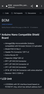
Am I missing something glaringly obvious? I saw references to the Bom talk about a .CSV file, unless it's only available on a computer (non-mobile browser) I must be missing something. Or is this as detailed as it gets? (Screenshot attached)
I have to admit, whilst the prospect of assembly and wiring etc is a daunting one, the initial task of buying the right bits seems to be causing me more concern!
I spent a good 15 minutes trying to work out for the life of me which 328p microcontroller on mouser to buy earlier (I'm unsure what I'm looking at!), and don't even get me started on the shield PCB. Any links to the bits you purchased would certainly be appreciated!
Many thanks
TT
Attachments
He did not use Mouser for anything. Almost everything comes from AliExpress. If you type in the generic names of the components you will get hits on AliExpress. For example type 238p microcontroller and the first thing that comes up is the type of board he used. I actually spent more and got a REAL Arduino nano too and used the clone boards for testing.

Thank you! Is there any advantage from using the real nano? Just to clarify, there isn't anything more specific or any more detailed list of components besides their general terms.
I'll definitely take that approach on AliExpress if required, just would like this to be as reliable as possible, but I'm also aware the correct operation is based on the clone parts (which has caused some issue for you at points!)
Many thanks
I'll definitely take that approach on AliExpress if required, just would like this to be as reliable as possible, but I'm also aware the correct operation is based on the clone parts (which has caused some issue for you at points!)
Many thanks
Last edited:
You can always ask here before you buy things.
The 'real' Nano and the clone boards do program differently when in the Arduino IDE app, but otherwise seem to work identical after being programmed. I have a socket for the Nano board and I ran my Shutter Tester from both types of boards and it runs identical.
The 'real' Nano and the clone boards do program differently when in the Arduino IDE app, but otherwise seem to work identical after being programmed. I have a socket for the Nano board and I ran my Shutter Tester from both types of boards and it runs identical.
Niglyn
Member
The clone Nano boards almost always come with the old bootloader installed. So if loading code via Arduino IDE, then 'use old bootloader' has to be selected. This often catches people out.
They also offer a choice of mini or micro USB connector. Functionally a clone or genuine Arduino are the same.
However, I believe the professional tester code is given as a HEX file?
Something like AVRDUDESS would need to be used. Select the 'Nano' preset of Nano boards with the old bootloader, our Uno preset for boards with the newer bootloader.
vandergus
Member
Alright, feeling a little dumb. Where is the source code on github? All I can find in /src is a demo file. It's surely not the complete code for the tester. What am I missing?
Technically there is no source code. Only a pre-compiled "Firmware" as a .HEX file. Listed under "Firmware" on the main page.
Good news is the Firmware is excellent. Better than I could write myself.
Link is here also: https://github.com/srozum/film_camera_tester/releases/tag/2.9.1
Good news is the Firmware is excellent. Better than I could write myself.
Link is here also: https://github.com/srozum/film_camera_tester/releases/tag/2.9.1
Here comes my build. I used the horizontal keypad but placed it vertically in order to fit a smaller aluminium enclosure. I also tried multiple types of acrylic boards and ended up with a 3mm PC diffuser. It performs almost the same with a 5mm thick acrylic but it is much thinner. I had to tune the power supply voltage up to 13.5V in order to reach 16EV. The linearity of the light source is pretty good and the maximum error is within ±0.2EV, which happens at both ends of the testing range. In order to fit the thinner diffuser and make the panel flat, I redrew and CNC a front plane using 3mm thick aluminum board, and it worked out great
with the enclosure.


with the enclosure.
I had to tune the power supply voltage up to 13.5V in order to reach 16EV.
Won’t that give the 12V rated LED a pretty short lifetime? Build looks great otherwise!
Last edited:
Not sure why my LED requires a higher voltage. But as long as the controller uses a PWM control and I seldom use 16EV which requires full power output, I think it should be fine for the LED. It it does break in the future, I will just replace one LED unit. I once guessed that it could be the diffuser that attenuating too much light. But after trying more than 3 diffusers, I decided to go with the 13+V.
Here comes my build. I used the horizontal keypad but placed it vertically in order to fit a smaller aluminium enclosure. I also tried multiple types of acrylic boards and ended up with a 3mm PC diffuser. It performs almost the same with a 5mm thick acrylic but it is much thinner. I had to tune the power supply voltage up to 13.5V in order to reach 16EV. The linearity of the light source is pretty good and the maximum error is within ±0.2EV, which happens at both ends of the testing range. In order to fit the thinner diffuser and make the panel flat, I redrew and CNC a front plane using 3mm thick aluminum board, and it worked out great
with the enclosure.
View attachment 349075
View attachment 349076
Fabulous! Thanks for sharing the pictures!
Not sure why my LED requires a higher voltage.
Make sure your LED driver PCB is configured correctly. I think it is worth investigating: “While adjusting the voltage be carefull to not exceed 13V or you can damage componets of the Tester!”
Source (under Calibration):
Light Source
DIY Film Camera Tester. Contribute to srozum/film_camera_tester development by creating an account on GitHub.
 github.com
The Nano takes up to 20v, the LED driver takes up to 25v, the only thing I could determine that is limited to 12V is the fan, but my experience with these fans is that they can handle a few extra volts. Otherwise, I suspect, a resistor could be placed in line with the fan.
Make sure your LED driver PCB is configured correctly. I think it is worth investigating: “While adjusting the voltage be carefull to not exceed 13V or you can damage componets of the Tester!”
Source (under Calibration):

Light Source
DIY Film Camera Tester. Contribute to srozum/film_camera_tester development by creating an account on GitHub.
I've replaced Rcs on LED driver board with a 91mR, so it should be fine.
I'm wondering if reflective material, such as tinfoil should be added to the inner surface of the reflector. I printed it with black ABS using an FDM printer. And I don't think it reflects too much light. Maybe adding tinfoil will help to improve the efficiency but will have negative impact on consistency.The Nano takes up to 20v, the LED driver takes up to 25v, the only thing I could determine that is limited to 12V is the fan, but my experience with these fans is that they can handle a few extra volts. Otherwise, I suspect, a resistor could be placed in line with the fan.
Not sure why my LED requires a higher voltage.
Btw, there was someone who I think had a similar problem to yours. The issue was a fresnel lens with a wrong focal length:
Light Source Calibration Issue · srozum film_camera_tester · Discussion #29
Hi Serhiy, So I started with a calibration of 12.5v as recommended from Light Source Wiki. I don't have a fancy luminance meter but I do have various camera hot shoe meters and digital cameras. At ...
github.com
Btw, there was someone who I think had a similar problem to yours. The issue was a fresnel lens with a wrong focal length:

Light Source Calibration Issue · srozum film_camera_tester · Discussion #29
Hi Serhiy, So I started with a calibration of 12.5v as recommended from Light Source Wiki. I don't have a fancy luminance meter but I do have various camera hot shoe meters and digital cameras. At ...
Disassembled my light unit and had it double checked. Focal length of the fresnel len was confirmed by placing it under sun light and measured the distance between the focal point and len surface. It is installed with smooth side facing LED and groves facing outward as required. So it should be fine.
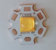
Now I suspect that I got a wrong LED. It looks like this :
As I live in China, I use TAOBAO instead of aliexpress. So I can't following the aliexpress links directly but look for same components on TAOBAO instead. Can you help to distinguish if it is the right one? Or maybe I should try something else from different vendor. This one cost me about 3USD here and I guess it can't be the REAL cree but a required FAKE one.
Ok, I guess you found the source of the issue. This does not look like the right one. The two dark squares and the thick separation lines inside the lens give it away.
Here is a link to a seller that should have the right one:
https://aliexpress.com/item/1005002137930742.html (12V, 20mm)
If you can’t ship within China, can you at least message the sellers on the platform and ask if they also have a Taobao store? Most should have one. The 3000K version should look like this:
Attachments
Last edited:
Ok, I guess you found the source of the issue. This does not look like the right one. The two dark squares and the thick separation lines inside the lens give it away.
Here is a link to a seller that should have the right one:
https://aliexpress.com/item/1005002137930742.html (12V, 20mm)
If you can’t ship within China, can you at least message the sellers on the platform and ask if they also have a Taobao store? Most should have one. The 3000K version should look like this:
The one I'm using is listed as a Epileds brand as suggested in the BOM. But I found that it actually has various versions. I might get one with wrong color temperature, which might lead to lower efficiency. I've placed order on some "warm-white" LEDs (listed as 3000K). I will update later when tested with the new ones.
The new LEDs arrived. And I've replace the previous one with it. It does show different light temperature but it doesn't show any different on output power. It still requires 13+V and the linearity is a little bit worst than the previous one.
Here comes the photo of both LEDs I get, the new arrival on the left and previous one on the right.

Here comes the photo of both LEDs I get, the new arrival on the left and previous one on the right.
| Photrio.com contains affiliate links to products. We may receive a commission for purchases made through these links. To read our full affiliate disclosure statement please click Here. |
PHOTRIO PARTNERS EQUALLY FUNDING OUR COMMUNITY:  |