Building A Professional Grade Shutter Tester

Takatoriyama

D
Takatoriyama

  • 4
  • 1
  • 60
Tree and reflection

H
Tree and reflection

  • 2
  • 0
  • 58
CK341

A
CK341

  • 3
  • 0
  • 68
Plum, Sun, Shade.jpeg

A
Plum, Sun, Shade.jpeg

  • sly
  • May 8, 2025
  • 3
  • 0
  • 95
Windfall 1.jpeg

A
Windfall 1.jpeg

  • sly
  • May 8, 2025
  • 7
  • 0
  • 76

Recent Classifieds

Forum statistics

Threads
197,622
Messages
2,762,064
Members
99,423
Latest member
southbaybrian
Recent bookmarks
0

FM2

Member
Joined
Jul 24, 2023
Messages
26
Location
Germany
Format
Multi Format
Wow, spot on. Thank you! This diode really is sensitive. It’s working now!

However, I find that the tester still crashes on startup if the sensor is not completely covered until the test is started (even if it is cased). So best practice seems to be putting sensor 6 on the camera first and then fire up the tester.
 
Last edited:

aconbere

Subscriber
Joined
Aug 2, 2023
Messages
248
Location
Seattle, WA
Format
4x5 Format
I thought I'd start by getting Sensor #2 working but I'm having a hell of a time. First I'm not sure whether I have an PIC0903SL or PIC0103SL. I've tried with both the 2.9.0 and 2.9.1 firmwares. In both cases when put into the frame opening it intermittently registers exposures, always with extremely large times. I assume something is up with my construction (the hole appears clear but who knows!).

I'm thinking about just swapping out the diode with another one but feels like I'm flying blind a bit.

1. Does anyone have a good procedure to identify which sensor I have?
2. Thoughts on a systematic test of the sensor?
 
OP
OP
ic-racer

ic-racer

Member
Joined
Feb 25, 2007
Messages
16,487
Location
USA
Format
Multi Format
I thought I'd start by getting Sensor #2 working but I'm having a hell of a time. First I'm not sure whether I have an PIC0903SL or PIC0103SL. I've tried with both the 2.9.0 and 2.9.1 firmwares. In both cases when put into the frame opening it intermittently registers exposures, always with extremely large times. I assume something is up with my construction (the hole appears clear but who knows!).

I'm thinking about just swapping out the diode with another one but feels like I'm flying blind a bit.

1. Does anyone have a good procedure to identify which sensor I have?
2. Thoughts on a systematic test of the sensor?

In my case it was clearly obvious. Are you sure when you swapped firmwares you actually uploaded the correct one? It would be easy to confuse them as they are labeled the same when you get them from the server.

Otherwise you can download the code for the tester below and wire up your sensors as shown in that thread and I think it would also be pretty obvious which sensors you have:
 

aconbere

Subscriber
Joined
Aug 2, 2023
Messages
248
Location
Seattle, WA
Format
4x5 Format
In my case it was clearly obvious. Are you sure when you swapped firmwares you actually uploaded the correct one? It would be easy to confuse them as they are labeled the same when you get them from the server.

Otherwise you can download the code for the tester below and wire up your sensors as shown in that thread and I think it would also be pretty obvious which sensors you have:
Not actually having the right firmware was my first concern! But the tester reports its version when starting up so I verified :-D

Hmmm I have used these before in the past with a little laser. I should probably just wire up the various diodes I have and see if VOUT is high or low in various conditions.
 

aconbere

Subscriber
Joined
Aug 2, 2023
Messages
248
Location
Seattle, WA
Format
4x5 Format
Okay so I can confirm that the sensor reads high when dark and low when lit. So I guess that means it's a PIC0103SL so I'll swap the firmware back to 2.9.1 and do some more testing.
 

aconbere

Subscriber
Joined
Aug 2, 2023
Messages
248
Location
Seattle, WA
Format
4x5 Format
I feel like I’m going a little crazy. It’s definitely acting like it’s measuring the dark when running 2.9.1

I put the sensor against the film gate. Hit start. The display reads “running”. I charge and fire the shutter (nothing). I do it again and it beeps and reads out a very incorrect timing 😵‍💫

Time to try 2.9.0 again! 😭
 
Last edited:

aconbere

Subscriber
Joined
Aug 2, 2023
Messages
248
Location
Seattle, WA
Format
4x5 Format
On 2.9.1 it pretty clearly measures dark. Gives me a couple seconds read out, about the time it takes me to recharge and fire the shutter.

On 2.9.0 it doesn’t seem to work correctly. I either get no reading or VERY small readings like 12us on a 1/60 shutter speed.

What the screen shows
 

aconbere

Subscriber
Joined
Aug 2, 2023
Messages
248
Location
Seattle, WA
Format
4x5 Format
I'm considering just ordering an entirely new set of sensors so I'm super confident in what they are. Is there a current sensor set that folks are buying and known correct?
 
OP
OP
ic-racer

ic-racer

Member
Joined
Feb 25, 2007
Messages
16,487
Location
USA
Format
Multi Format
On 2.9.1 it pretty clearly measures dark. Gives me a couple seconds read out, about the time it takes me to recharge and fire the shutter.

On 2.9.0 it doesn’t seem to work correctly. I either get no reading or VERY small readings like 12us on a 1/60 shutter speed.

What the screen shows

I think you are on the correct track.
Now look at the sensor in the box. It may be that the hole is not aligned with the little lens. The printing on the PC board is not correct.
234424530-8939d01d-d634-4421-bdd8-033be5202f6b.png
 
Last edited:
OP
OP
ic-racer

ic-racer

Member
Joined
Feb 25, 2007
Messages
16,487
Location
USA
Format
Multi Format
When I first assembled sensor#2, with incorrect alignment, it only responded to off-axis light from my overhead lights. Light coming straight from the Camera Tester's light source would not trigger it.


aconbere

Subscriber
Joined
Aug 2, 2023
Messages
248
Location
Seattle, WA
Format
4x5 Format
Interesting… for hole alignment I actually positioned the sensor into the hole, then adjusted the legs to fit the pcb so i’m fairly confident there.

I’m leaning towards potentially a bad sensor… orrrr damage when removing the little ledge?

In either case my next step is going to be replacing the sensor and trying again. Here’s hoping!
 

aconbere

Subscriber
Joined
Aug 2, 2023
Messages
248
Location
Seattle, WA
Format
4x5 Format
No luck with the new sensor. Next thought is just that my hole isn’t lined up nicely and things aren’t fit well. Two options, second swing at sensor 2, I have a spare lid printed and I could just drill new holes and try again.

Curious how folks are approaching alignment and maybe I’m just doing it wrong.

I did uncover another issue where it seems like the light unit is noisy and I get a bunch of false readings when it’s on 😰
 
OP
OP
ic-racer

ic-racer

Member
Joined
Feb 25, 2007
Messages
16,487
Location
USA
Format
Multi Format
I thought building the sensors was the hardest part of the whole thing. I did a lot of trial and error.

I tried gluing the sensor right to the lid. But the epoxy did not hold well and the force of the legs soldered to the PC board made it shift.

I was next going to try to just use jumper wires , but there is not much room. So I gave up on that.

Next I counter sunk the holes, so alignment would not be such an issue and holes drilled at a slight angle would not matter as much.

To make sure everything was aligned I compared measured speeds with a focal plane shutter with the sensor in different orientations and the speeds are close (but not exact).

Picture, Glued Sensor. Did not work as expected:

glued sensor.jpeg
 
OP
OP
ic-racer

ic-racer

Member
Joined
Feb 25, 2007
Messages
16,487
Location
USA
Format
Multi Format
Make sure the face of the sensor is perfectly flat by removing the step up. I used a razor blade to protect the lens while filing it flat.
file 2.jpg
file 1.jpg
bent.jpeg
 

aconbere

Subscriber
Joined
Aug 2, 2023
Messages
248
Location
Seattle, WA
Format
4x5 Format
Back with no luck. I've carefully filed down the edges of the sensors, and counter sunk the holes.

This time around I attached the PCB to the body of the sensor and used a drill press to drill through the guide hole to ensure alignment. When soldering the sensor to the PCB I then aligned the lens with the hole. I can feel that this sits nicely in the counter sunk hole by moving the PCB around and feeling the lens drop into the hole.

At this point I'm inclined to believe there must be some other issues going on. Unfortunately I blew up my last nano accidentally shorting GND and VCC when checking to make sure that there wasn't some weird dip going on (VCC was holding pretty nicely at around 4.95v). Anyway I think that's what will be next. I've got more nano's coming, and I'll just start probing all the signals and seeing what I can see. It should be fairly obvious on the scope when the shutter opens and closes and if that's looking good then the bug is somewhere other than the sensor.
 
OP
OP
ic-racer

ic-racer

Member
Joined
Feb 25, 2007
Messages
16,487
Location
USA
Format
Multi Format
Another way I tested my sensors was to use the sensor out of the enclosure and shine a laser at the sensor. Then put a focal plane shutter anywhere in the beam. It should give accurate readings if everything is OK.
 
Last edited:

aconbere

Subscriber
Joined
Aug 2, 2023
Messages
248
Location
Seattle, WA
Format
4x5 Format
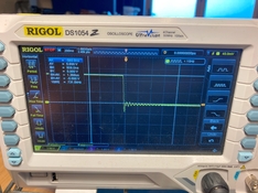
Okay! So got the sensor on the scope and this seems.... good? This is just the falling edge from the shutter opening. (If anyone knows how to set up a double trigger on a Rigol I'd be happy to show what this looks like for capturing the full curtain travel). This is obviously one of the newer sensors where dark is high and light is low. But this doesn't explain ANYTHING about why it's been giving me hell and not working at all. So I'm thinking something else must be wrong.
 

Attachments

  • IMG_3019.jpg
    IMG_3019.jpg
    827.9 KB · Views: 48
OP
OP
ic-racer

ic-racer

Member
Joined
Feb 25, 2007
Messages
16,487
Location
USA
Format
Multi Format
Double and triple check the wiring of the probe and the sockets.
 

aconbere

Subscriber
Joined
Aug 2, 2023
Messages
248
Location
Seattle, WA
Format
4x5 Format
My scope is probing the pin off the connector on the inside of the case. What i’ll do today is figure out the wiring and probe off the arduino socket. Then it will test the end to end wiring (and I’ll figure out how to get the scope to record the rising and falling edges).
 

aconbere

Subscriber
Joined
Aug 2, 2023
Messages
248
Location
Seattle, WA
Format
4x5 Format
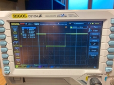
Here's the probe, scoped at the arduino's pins, through a full shutter actuation.

This looks perfect to me. Today I'll reflash a nano with 2.9.1 and see if I can get the tester to work, but I'm not holding a lot of hope.

Side Note: I'm a little surprised that there weren't current limiting resistors in the lines to the probes. I can't imagine that they need very much current to run and that would protect the arduino's voltage regulator from shorts. I rebuilt most of the boards in KiCad as an exercise and I wonder if it would be worth trying to get some small changes like that in.
 

Attachments

  • IMG_3023.jpg
    IMG_3023.jpg
    893 KB · Views: 48

aconbere

Subscriber
Joined
Aug 2, 2023
Messages
248
Location
Seattle, WA
Format
4x5 Format
Okay, new nanos came in this morning. Flashed with 2.9.1.

I don't have a great adapter to lift the leg on the nano, so I'm just probing between the connector on the inside of the case and ground on the nano. I have the light disconnected for now to simplify, using a bright local light source instead. No other probes are connected.

The system boots, reports version 2.9.1

I start the simple shutter tester with the probe attached to the back of the body. Point at the light and fire the shutter.

There are three cases I've seen:

1. The tester reports nothing - but the the scope displays a nice clean pulse.
2. The tester reports an actuation - but it is WILDLY inaccurate. Example: Based on the scope I can measure a 21ms exposure for what the camera thought would be 1/60th. The tester reports this as 8 seconds.
3. The tester starts going off like crazy reporting lots of actuations - No square wave on the scope (but it does look like maybe some increase in picked up noise).

So at this point I feel like I'm running out of ideas haha it feels to me like there has to be a bug in the firmware? Or maybe there's an noise floor that I'm exceeding but hasn't been accounted for in the software? Noise seems "okay" during normal operations minus whatever is going on with 3.

HMPF
 
Last edited:

aconbere

Subscriber
Joined
Aug 2, 2023
Messages
248
Location
Seattle, WA
Format
4x5 Format

aconbere

Subscriber
Joined
Aug 2, 2023
Messages
248
Location
Seattle, WA
Format
4x5 Format
Oh! I got a response in the github discussion, he caught it immediately. I wired the sensor incorrectly. The sensor pin labeled A goes to the connector pin labeled A/B not A/A. Ooops. That's fixed issues 1 and 3. Not registering actuations, and way too many. Trying out 2.9.0 to see if it fixes the long recorded times.
{moderator's note - fixed that double negative for you}
{ Author's note - oops! we had conflicting editing fixes and now it's backwards again - Fixed now}
 
Last edited:
Photrio.com contains affiliate links to products. We may receive a commission for purchases made through these links.
To read our full affiliate disclosure statement please click Here.

PHOTRIO PARTNERS EQUALLY FUNDING OUR COMMUNITY:


Ilford ADOX Freestyle Photographic Stearman Press Weldon Color Lab Blue Moon Camera & Machine
Top Bottom