-
Welcome to Photrio!Registration is fast and free. Join today to unlock search, see fewer ads, and access all forum features.Click here to sign up
- Home
- Forums
- Analog Workflow Forums (100% Analog/Traditional)
- Analog Equipment
- Camera Building, Repairs & Modification
You are using an out of date browser. It may not display this or other websites correctly.
You should upgrade or use an alternative browser.
You should upgrade or use an alternative browser.
Build a shutter tester for Focal Plane shutters - Cheap, Easy & it Works
-
A
- Thread starter Niglyn
- Start date


Recent Classifieds
-
For Sale Fuji GW670 III
- Started by campy51
-
For Sale Hasselblad X Pan w/ 45mm/f4 Lens
- Started by eftones
-
For Sale 6 antique French pneumatic shutters _ Guerry
- Started by Manual Camera
-
For Sale Voigtländer Nokton Classic 35mm/1.4 with Leica M-mount
- Started by Klaus Mähring
-
For Sale Voigtländer Bessa R2 Special Edition Olive Green
- Started by Klaus Mähring
Forum statistics
- Threads
- 204,295
- Messages
- 2,866,727
- Members
- 102,213
- Latest member
- PabloThePhotographer
- Recent bookmarks
- 0
Ports 39 34 36 require pull up, and don't see any on your descriptions
Pins, not ports, and they can be pulled up in software. I virtually never use hardware pullups.
Pins, not ports, and they can be pulled up in software. I virtually never use hardware pullups.
Hi, no all pins GPIO have pull up and down integrated in the ESP32 execpt pins GPIO36, GPIO39, GPIO34, GPIO35. If the digitalpin (eg: 36 is configured to "high" and you turn de rotary button as the same time, you will probably burn the "pin". I just ask that to make a PCB for Nyglin, i don't have the code so i can't make it without any informations. Pin, ports my english is pretty far now so by the way sorry for that!

Niglyn
Member
Hi, Ports 39 34 36 require pull up, and don't see any on your descriptions, is it because you're are using a specific rotary button with internal pull up?
Hi, yes the encoder has built in pull-up resisters, hence the 4v supply required,
Niglyn
Member
Hi, no all pins GPIO have pull up and down integrated in the ESP32 execpt pins GPIO36, GPIO39, GPIO34, GPIO35. If the digitalpin (eg: 36 is configured to "high" and you turn de rotary button as the same time, you will probably burn the "pin". I just ask that to make a PCB for Nyglin, i don't have the code so i can't make it without any informations. Pin, ports my english is pretty far now so by the way sorry for that!
Hi, Your English is fine. I can barely speak a second language, let alone write in it.
The specified encoder has pull-up resisters & capacitors built in.
I deliberately connected the encoder to the ESP32 pins that do not have internal pull-up resisters.
As for a pcb, I was thinking a daughter board, where both the ESP32 development board and TFT plug into. With all the TFT & toucj connections routed on the pcb.
Other connections routed to screw terminals.
Hello,
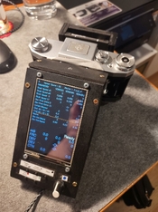
a quick update from me. The unit is now running, and I've been able to take my first measurements with my 70-year-old Praktica.
The long times seem to be correct. The short ones show quite clearly that ther is friction involved.
What I haven't been able to get working yet, is to get the SD card mounted upon startup.
Regards,
Backfocus
Attachments
Hello,
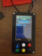
Can I get auth key for my esp32 build, the reference code is 81333248.
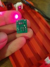
Btw I had trouble with the sensors I bought, they were showing seen in the test screen and only showed blocked if I crush them between my fingers.
But then I remembered post in this thread mentioning defective bundle 5 sensors plus 5 laser pack like mine so I checked the aliexpress order and the article page thinking maybe I need to connect the sensor in different way. I knew they somewat work, because I tested them and saw voltage output when shone with light.
Luckily someone had left comment with solution, problem being with the board missing connection. Everything seemed to work after the modification and I am getting plausible results mostly I think.( third picture is copied from the ali poster)
Now it will be interesting to see if I get the same results with the 3 sensor version compared to arduino when using the same sensor/laser setup.
Also Niglyn what do you think about the fix, arethere potential issues with it.
Can I get auth key for my esp32 build, the reference code is 81333248.
Btw I had trouble with the sensors I bought, they were showing seen in the test screen and only showed blocked if I crush them between my fingers.
But then I remembered post in this thread mentioning defective bundle 5 sensors plus 5 laser pack like mine so I checked the aliexpress order and the article page thinking maybe I need to connect the sensor in different way. I knew they somewat work, because I tested them and saw voltage output when shone with light.
Luckily someone had left comment with solution, problem being with the board missing connection. Everything seemed to work after the modification and I am getting plausible results mostly I think.( third picture is copied from the ali poster)
Now it will be interesting to see if I get the same results with the 3 sensor version compared to arduino when using the same sensor/laser setup.
Also Niglyn what do you think about the fix, arethere potential issues with it.
Attachments
kur1j
Member
So I am wanting to get a camera tester to debug/validate my camera shutter problems (capping as an example).
I was considering getting a Reveni Labs, https://www.reveni-labs.com/reveni-labs-camera-tester unit. I don't mind a project, but I don't really want to debug problems with testing equipment.
I ran across this unit and had a few questions.
1) Has anyone validated this setup with faster shutter speeds (e.g. 1/1000 or faster)?
2) I have a 3d printer and want to build cases to make this more usable (rather than stray wires coming out of everywhere), but seems like the 3d printed parts are an after thought, does anyone have good print files for this?
3) How do people deal with RELIABLE alignment of the lasers/sensors?
4) Has anyone reliably used this to test their cameras shutters or has it been more so a project in itself (e.g. this https://www.photrio.com/forum/threa...eap-easy-it-works.197756/page-21#post-2838553). "Right now I'm at a dead end and I can't figure out if the problem is with the shutter or the shutter tester". This scares me as problem with testing equipment. If you can't trust the tool its as good as a waste of time and worthless. Not trying to be critical of a "free" project, I commend it, but at the same time I want to utilize a tool for its purpose, don't want to be 7 layers deep in debugging to debug other debugging problems.
5) Kind of going with 2) is there good instructions/3d prints for building out cases for these these units?
Niglyn
Member
Hello,
Can I get auth key for my esp32 build, the reference code is 81333248.
Btw I had trouble with the sensors I bought, they were showing seen in the test screen and only showed blocked if I crush them between my fingers.
But then I remembered post in this thread mentioning defective bundle 5 sensors plus 5 laser pack like mine so I checked the aliexpress order and the article page thinking maybe I need to connect the sensor in different way. I knew they somewat work, because I tested them and saw voltage output when shone with light.
Luckily someone had left comment with solution, problem being with the board missing connection. Everything seemed to work after the modification and I am getting plausible results mostly I think.( third picture is copied from the ali poster)
Now it will be interesting to see if I get the same results with the 3 sensor version compared to arduino when using the same sensor/laser setup.
Also Niglyn what do you think about the fix, are there potential issues with it.
Hi, first of all apologies. Photrio seems not to be sending me an email when somebody posts or PMs, so unless I check in, I cannot see new posts.
Thank you for taking the time to post the issue and more importantly, the solution.
As for the sensor board issue. Ideally I would like one in my hand to look at, or at the least a photo of the component side.
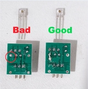
But from what I can surmise by looking at the photos and comparing it to an original pcb, it seems somebody has copied the original pcb layout, changing it slightly, muffing it up, making two errors.
This board has a slightly different layout to the original, the solder pad circled in red has been moved up.
It seems that this solder pad is not connected to any pcb track.
Assuming on the other side, it is the pullup resister, then as correctly shown in the OPs photo, it should be connected to the pad below.
The second error that I can see on the 'good board' (but it looks ok on the 'Bad' board photo), the pcb track from the smoothing capacitor just stops and does not continue to the top-left.
In the 'Good' photo below, I have highlighted in yellow, the two errors, where wire links require soldering.
Why the pcb design has changed, I have no idea. I have two variations in my collection, the pcbs are identical, but the screen printing is slightly different.
Whether there is just one pcb manufacturer of this board & they have slightly changed it & goofed up, or another company has decided to copy the design, who knows.
Niglyn
Member
So I am wanting to get a camera tester to debug/validate my camera shutter problems (capping as an example).
I was considering getting a Reveni Labs, https://www.reveni-labs.com/reveni-labs-camera-tester unit. I don't mind a project, but I don't really want to debug problems with testing equipment.
I ran across this unit and had a few questions.
1) Has anyone validated this setup with faster shutter speeds (e.g. 1/1000 or faster)?
2) I have a 3d printer and want to build cases to make this more usable (rather than stray wires coming out of everywhere), but seems like the 3d printed parts are an after thought, does anyone have good print files for this?
3) How do people deal with RELIABLE alignment of the lasers/sensors?
4) Has anyone reliably used this to test their cameras shutters or has it been more so a project in itself (e.g. this https://www.photrio.com/forum/threa...eap-easy-it-works.197756/page-21#post-2838553). "Right now I'm at a dead end and I can't figure out if the problem is with the shutter or the shutter tester". This scares me as problem with testing equipment. If you can't trust the tool its as good as a waste of time and worthless. Not trying to be critical of a "free" project, I commend it, but at the same time I want to utilize a tool for its purpose, don't want to be 7 layers deep in debugging to debug other debugging problems.
5) Kind of going with 2) is there good instructions/3d prints for building out cases for these these units?
Hi, Reveni Labs is a fine tester. I have communicated with the designer/owner & he is a nice chap.
1) The Shutter Tester should work fine up to 1/8000s. Higher speeds than 1/10000s are recorded but report as an error. Personally I have not tried testing above 1/1000s.
2) This is a DIY build, were it to be turned into a manufactured product, the cost would be the same as Reveni. There are some basic 3d print files available on Github and some people have made their own 3d printed cases & holders, but nobody, as far as I know have put their print files on the web, or allowed me to add them to the Github.
3) I just used a tape measure to space the sensors. After all, we are looking for consistency not ultimate accuracy. Alternate is to make a mask and drill holes at exactly 32mm, or 3d print one.
I have added 3d files for the Lasers, a marking guide for the box and a bezel for the screen, but not got round to drawing one for the sensors, as these are slightly more tricky due to the protrusion on the sensor, which may involve a little trial and error to get the recess correct & I do not have a printer to make test prints.
4) Yes, lots of people use The Shutter Tester to repair & check their cameras. I use it & is why I built it in the first place.
You have to be careful with DIY/free/cheap shutter testers as they may suffer from a known problem, which has been discussed at length. The problem is, we are trying to measure a single photon which effectively has no width, with electronic sensors which of course do. So you measure not only the slit width (to get shutter 'speed') but also the width of the sensors & their hysteresis as well.
Of the free open source code I have looked at, not one addresses the issue above. Similarly of the ones available pre-built on ebay etc, they make no mention of this either.
As far as I am aware The Shutter Tester is the only tester available that details this problem, addresses and corrects for it.
I am not saying other pre-built testers do not also correct for it, but their documentation makes no mention of it.
Yes, The Shutter Tester is a bit of a project. I, being an electronics/software person who also likes to tinker with all sorts, clocks, cameras etc, thought it would be easy to make a shutter tester. Well it turns out it is not, see paragraph above.
When this issue was solved, I continued to refine the functionality and usability of The Shutter Tester. Sometimes at the request of users, other times just things I thought of, like changing the screen colour or having different screen layouts, for example.
There is no debugging to be done. As you can see from all of the satisfied builders and users in this group. Ok occasionally we get a curve ball, like this batch of faulty sensor pcbs, but as you can see from the threads above, it has been quickly addressed.
I suppose it all really depends on you, how much you want to spend, if you like building stuff, how many cameras you want to test etc.
The Shutter Tester is as accurate, if not more so, than any other available tester. If you want a ready built new product, your only real option is Reveni. However, the same questions get asked, how accurate is it compared to a 'professional' tester.
Alternate is to buy a 1970s tester. How accurate do you think it will be after all of these years. First step would be to find a calibration company who have the facilities to calibrate it.
Then we have the 'what is shutter speed' question. If you have never tested shutters before, the first thing is how horrified you will be on how inconsistent and inaccurate they are. Just look at the ISO standard for shutter speed deviation.
So what you really want is consistency of the tester, Who cares if 1/500s reads as 1/498s or 1/30s reads as 1/29s
(The Shutter Tester reads accurately, the above is just an example about consistency vs accuracy)
The old professional testers, full of 1970s cmos logic chips will never be as 'accurate' or consistent as a modern day microprocessor. They used logic chips, not microprocessors, so could not cleverly adapt for sensor width. their solution, if you look, was to have very long but very thin light dependant resisters, hidden under a thin slot. This way they could get the full shutter depth of light, but in a narrow beam, similar to a modern day mask.
Now, these long thin resisters were bespoke components and no longer available today. They were also stuck with their slot width, whilst minimising the error caused by sensor width, were still not immune from it.
5) You could always try PMing posters here who have made their own cases & ask if they will share their design. Alternate is to start learning cad. There are pleny of free ones out there & tutorials on youtube.
I have cad/cam/machining cnc experience, hence have added a few parts to the Github. However the whole point of this tester is for people to be able to make it just using basic hand tools & a soldering iron. There are no complicated pcbs to make, no parts to be 3d printed.
Yes it could be neater with a pcb and 3d printed case, this is open to anyone if they wish to design and make them. I'm happy to put the files & details on the Github.
At some point, still a long way off, I will get a 3d printer and start making parts, cases etc. These I will sell for cost price & make the files available for free. But for the moment, I do not want to generate 3d print files, as I will not be able to test and refine them on a printer, before making them publicly available.
Last edited:
Niglyn
Member
Would be nice if there was a "Heathkit" of this.
Hi, I did think of making a kit of parts. However with people from all over the world it would require expensive postage.
So instead, I decided to make the parts list with links to Aliexpress, who ship worldwide and give free postage.
Photrio seems not to be sending me an email when somebody posts or PMs, so unless I check in, I cannot see new posts.
@Sean, please be informed of this; could you check whether there's an account settings problem? @Niglyn, the most common and obvious cause of this is Photrio's automated emails being qualified as spam, so please be sure to check your spam folder and whitelist @photrio.com emails. Keep in mind that email updates are on an opt-in basis for thread posts (but I assume you actually opted in for your thread?), but they are 'on' by default on PM's.
In any case, sorry for any inconvenience caused, and thanks for your continued commitment to answering people's questions!
Niglyn
Member
HI, Here is a photo of the original sensor pcb.
I have circled in yellow the pad, which is correct on this board, attaching to the small rectangular copper area below.
Compare this to the new (faulty) board where this pad has been moved up and is not connected to the copper traces on the pcb.
Note, if modifying a faulty board, you have to scratch off the green coating to expose the bare copper below.
Niglyn
Member
@Sean, please be informed of this; could you check whether there's an account settings problem? @Niglyn, the most common and obvious cause of this is Photrio's automated emails being qualified as spam, so please be sure to check your spam folder and whitelist @photrio.com emails. Keep in mind that email updates are on an opt-in basis for thread posts (but I assume you actually opted in for your thread?), but they are 'on' by default on PM's.
In any case, sorry for any inconvenience caused, and thanks for your continued commitment to answering people's questions!
Hi, it seems if I do not log into Photrio for a while. the email alerts stop. But once I log in, they start up again for a while.
Almost as if there is a setting 'stop sending emails if user has not logged in for x number of days'
Hm, that's odd; I'm not aware of any such feature. Hopefully @Sean finds a moment to investigate.Hi, it seems if I do not log into Photrio for a while. the email alerts stop. But once I log in, they start up again for a while.
Almost as if there is a setting 'stop sending emails if user has not logged in for x number of days'
There's 31 web pages of this and I'm late to the party. Interesting, though. My question is, what is used for the calibration standard after building it? You can't just build a shortwave radio out of parts you bought from a parts list, and have that to be the end of the project. You have to align it afterwards, which means you need a sweep generator and a scope to align it. How is this project any different on getting it calibrated to some reasonable degree of lab standard after you've built it? Thank you.
The timing relies ultimately on the clock of the microcontroller. This fed from a regular external crystal oscillator. The accuracy of a typical crystal oscillator is in the order of 20-30ppm, let's say less than 100ppm in any case even under adverse conditions. A critic may argue that this can be spoiled by poor software design, but I'm sure @Niglyn has avoided the main pitfalls.There's 31 web pages of this and I'm late to the party. Interesting, though. My question is, what is used for the calibration standard after building it? You can't just build a shortwave radio out of parts you bought from a parts list, and have that to be the end of the project. You have to align it afterwards, which means you need a sweep generator and a scope to align it. How is this project any different on getting it calibrated to some reasonable degree of lab standard after you've built it? Thank you.
No calibration will be required, ever, and the device will still be way more accurate and consistent than it needs to be for this application.
Niglyn
Member
There's 31 web pages of this and I'm late to the party. Interesting, though. My question is, what is used for the calibration standard after building it? You can't just build a shortwave radio out of parts you bought from a parts list, and have that to be the end of the project. You have to align it afterwards, which means you need a sweep generator and a scope to align it. How is this project any different on getting it calibrated to some reasonable degree of lab standard after you've built it? Thank you.
Hi, thanks for the interesting question & for posting,
Yes, we are up to 31 pages! However this is the forum/user/discussion group.
You do not need to read any of this to build The Shutter Tester.
All of the build, user guides, parts list etc are found in the Github.
In the 1970s, using discrete components, potential dividers, to get the required voltage, with resisters of 20% tolerance etc, things could drift. Electronics would need aligning, local oscillator, IF modulator, discrete power rails etc.
However, it is not the 1970s anymore and modern microcontrollers can replace hundreds of discrete components.
The ESP32 specified, runs at 240Mhz, Each cpu cycle is 4 nano seconds.
The oscillator accurate to 20-30ppm. It has ic power regulators. No calibration required.
We can run up to 62500 basic instructions in the time it takes to measure a shutter speed of 1/1000s
The code is efficiently written for accurate timing results and to minimise jitter & latency within the measuring cycle.
I do not understand your line
'how is this project any different on getting it calibrated to some reasonable degree of lab standard after you've built it?'
Different to what?
When one first gets into camera repair, the first thing one is shocked by, is how inaccurate shutters on old mechanical cameras are.
If you expect to see a test result of 1/30s, 1/125s. 1.250s etc, think again. Look at the ISO standard for shutter speed and see how wide they are.
You may have seen some posts from users querying why their serviced camera, when tested on The Shutter Tester is not giving 'accurate' results. Well the sad truth is, The Shutter Tester is giving accurate results, it is the camera that was serviced to the ISO tolerance, for example 1/500s or 2ms can be between 1.43ms and 2.67ms
There was a great post from a chap getting very bad readings on The Shutter Tester. He then tried a roll of film. And yep, The Shutter Tester was 100% accurate and his camera had serious issues.
So whilst The Shutter Tester is accurate, one must not get caught up in trying to get a camera to be exactly 1/500s or 1/125s as, as you adjust one speed, the others will change and it will drive you mad.
It is more important to get consistency of readings, the curtain travel times within the service manual specification and the shutter speeds all within ISO tolerance.
It would easily be possible for The Shutter Tester to output a 100khz frequency (or any other frequency), driven from the oscillator, for a user to send it to a calibration lab, to check the accuracy of the oscillator, however, I can't really see anybody going to the expense of doing this.
I started doing some due diligence by reading the first 4 pages of this thread.27 more to go I suppose. I've never used Github, but just went on to do a search by typing in "shutter tester". Apparently there's 46 of them. No way I can know which one is the one in this thread. Also, there seemed to be a situation where only the user Niglyn has tthe code needed to program it. For what it's worth, I've restored a LOT of ham radio gear, oscilloscopes, signal genrators, R to R tape recorders, and lots of other things. Also I'm pretty good at Freecad and have a couple nice 3D printers. One has a .2mm tip that can print extremely high detail in PLA. So I'm sure I can contribute stl's to the forum for a nice cabinet for this device. Thank you.
| Photrio.com contains affiliate links to products. We may receive a commission for purchases made through these links. To read our full affiliate disclosure statement please click Here. |
PHOTRIO PARTNERS EQUALLY FUNDING OUR COMMUNITY:  |