Why is Zone System EI often about half rated ISO/ASA?

Amsterdam protest

A
Amsterdam protest

  • 0
  • 0
  • 0
Service Entrance

A
Service Entrance

  • 1
  • 1
  • 30
Trash and razor wire

A
Trash and razor wire

  • 1
  • 0
  • 21
Bicycles chained

Bicycles chained

  • 0
  • 0
  • 18
Tubas in the Park

A
Tubas in the Park

  • 1
  • 0
  • 19

Recent Classifieds

Forum statistics

Threads
197,858
Messages
2,765,801
Members
99,488
Latest member
colpe
Recent bookmarks
0

RobC

Member
Joined
Nov 5, 2007
Messages
3,880
Location
UK
Format
Multi Format
This intrigues me. I hope that there can be a wider discussion of this.

Each stop is twice or half as much light as previous. If we shine 512 units of light at a target then if there were 11 cards each with a reflectance of twice the previous then:

0=1/2
1=1
2=2
3=4
4=8
5=16
6=32
7=64
8=128
9=256
10=512

So the mid point is 5 which will reflect 16 units of light. 16 is 3.125% of 512.

The point where 18% is reflected is where the reflectance is 92.16 units of light and that is between card 7 and card 8, 2 1/2 stops less than the full 100% of 512.

If we have 6 cards and shine 16 units of light at them, then;

0=1/2
1=1
2=2
3=4
4=8
5=16

The mid point is between cards 2 and 3 which is 3 units of light. 3 is 18.75% of 16 which is close enough and is 2 1/2 stops from 100% of reflectance.
18% is always 2 1/2 stops less than whatever is 100% reflectance in the same light.

However, its not that simple. The first example above is a false representation of real life except in a lab prepared experiment.
The second example of 5 stop range is more life like.

But again its more difficult than that becasue your spot meter does more stuff to reduce the reading. It divides by approx 12.5 which is same as taking 8% of the reading.

trying to keep all this in your head when doing practical photography simply isn't necessary.

Typically the part of your subject which is in direct light will represent only a portion of that range and the other portion will be in varying degrees of shade. So where do you place your grey card if you are using one? The answer is to tear it up and forget all about grey cards and use a spot meter to measure an actual highlight and shadow, determine the range and decide whether you want to expose for a shadow or a highlight and place the exposure where you want it on your film curve. If you must use a grey card then you may as well use an incident meter which will likely be more consistently accurate due to difficulty of using a grey accurately which requires specific angles between card, light source and camera for it to give an 18% reflectance.

Personally I have adopted the methodolgy of calibrating EI and Dev to capture that full 10 stop range so thats its printable on G2 paper. I then meter for and expose for a highlight except where the range is too long in which case I expose for a shadow.
 
Last edited by a moderator:

cowanw

Member
Joined
Aug 29, 2006
Messages
2,221
Location
Hamilton, On
Format
Large Format
Does this mean that if one (stupidly but with correct accuracy) spot meters off a grey card in the scene and develops and prints such that your 512 units of light are correctly represented, that that part of the image that is the grey card will be Zone 7?
 

RobC

Member
Joined
Nov 5, 2007
Messages
3,880
Location
UK
Format
Multi Format
Does this mean that if one (stupidly but with correct accuracy) spot meters off a grey card in the scene and develops and prints such that your 512 units of light are correctly represented, that that part of the image that is the grey card will be Zone 7?

Take a bright white piece of paper and put it in direct sunlight. Place a grey card against it and then meter both. How many stops difference are there ?

I would suggest it will be about 2 1/3 stops. Infact you can use the reverse side of the grey card if its a genuine Kodak one. Just make sure the card is in same plane when you turn it over and meter position is same.
 

DREW WILEY

Member
Joined
Jul 14, 2011
Messages
13,787
Format
8x10 Format
Now place a a seam of white quartz poking thru granite in the scene, along with some reflective mica or a sunlit snow patch. Adjacent to it,
some black volcanic rocks in deep shadow. The story of my life. Ten to twelve stop ranges. No wonder I always seem to get in film arguments with people who live in smoggy cities where the contrast is soft and a gray card left outdoors overnight becomes a brown card.
Due to such inevitable differences, one should think of the Zone System as an elastic rubber band, and not a set of decrees on a stone tablet.
 

cowanw

Member
Joined
Aug 29, 2006
Messages
2,221
Location
Hamilton, On
Format
Large Format
Take a bright white piece of paper and put it in direct sunlight. Place a grey card against it and then meter both. How many stops difference are there ?

I would suggest it will be about 2 1/3 stops. Infact you can use the reverse side of the grey card if its a genuine Kodak one. Just make sure the card is in same plane when you turn it over and meter position is same.

I will do that, but I was enquiring about how it prints, not how it meters.
 

RobC

Member
Joined
Nov 5, 2007
Messages
3,880
Location
UK
Format
Multi Format
I will do that, but I was enquiring about how it prints, not how it meters.

That depends on your calibration of EI and Dev which I have no idea about.

It also depends on what zone you place it on and also it depends on what you set your print time to, white or middle grey.

So I need to know those also before I can answer with a degree of accuracy.

You can't just say white will print as white becasue if you metered and place the grey card on zone 5 white won't print as white.

But if you have metered white and placed it zone 10 and print time is set for zone 10 then yes the grey card print approx 2 1/2 print values darker if calibration was for a 10 stop range. Or print value 6 1/2 if you calibrated for 7 1/3 stop range.

Theres too many variables which I don't know.

Oh, and if you meter the card and place it on zone 7 and print for a zone 7 then you will be about right if you've calibrated for a 10 stop range.
 
Last edited by a moderator:

cowanw

Member
Joined
Aug 29, 2006
Messages
2,221
Location
Hamilton, On
Format
Large Format
Oh, and if you meter the card and place it on zone 7 and print for a zone 7 then you will be about right if you've calibrated for a 10 stop range.

I appreciate there are many variables; and I appreciate your frankness.
Referring to your last sentence and with regards to placing the tone of the grey card in Zone 7, if the card is metered as part of a 10 brightness range (your EI and development) and the suggested camera settings are used as read, I interpret, that, that is, by definition, placing the tone of the card in Zone 7.
Consequently, to place that tone in Zone 5, the suggested exposure will be reduced by 2 stops.
Do I understand you correctly?
 
Joined
Jan 7, 2005
Messages
2,603
Location
Los Angeles
Format
4x5 Format
But if you have metered white and placed it zone 10 and print time is set for zone 10 then yes the grey card print approx 2 1/2 print values darker if calibration was for a 10 stop range. Or print value 7 if you calibrated for 7 1/3 stop range.

Thanks for finally explaining your approach. You're using a ten stop range and fitting it on the full range of the paper. Makes sense. What I think you are missing is the 7 1/3 stop calibration part. The range of the paper for the 7 1/3 stop test is shorter than the full range of the paper. The remainder of the 10 stop range falls outside "aim" density range for the 7 1/3 stop test willing the full range of the paper. The results are basically the same.

Adams' 1.15 - 1.25 NDR (after subtracting 0.10 over Fb+f) is based off the dynamic range (I to VIII), not full black to white(I to X). In addition the 1.30 comes from the no flare Zone System test. In actual use, the range is reduced due to flare. The resulting NDR falls around the 1.05 LER for Grade 2 paper.

Matching the negative's NDR to the paper's LER is will just give you the ballpark. One of the problems with photography is that it can't be easily defined using psychophysics. It's not as straight forward as a certain color temperature of light being perceived as blue. The photograph is more subjective. I hesitate to say it's because photography is an art because not everyone uses it for artistic purposes. Jones published two lengthy papers on paper grades and negative matching in the late 1940s. The tests weren't about creating specific criteria for paper grades, but to determine the best approach to objectively determine sensitometrically the paper grade that will consistently produce high quality prints. Jones concluded, “because of the influence of the brightness distribution and subject matter in the scenes photographed, an accurate prediction cannot always be made of the exposure scale (Log Exposure Range) of the paper which will give a first-choice print from a negative of known density scale (Density Range)… But what other course is there to follow? Either we must make the best of a somewhat imperfect relationship or face the prospect of having no criterion whatever for choosing the paper contrast grade.”

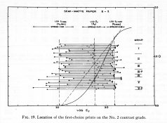
I think the following example from Jones' paper dramatically illustrates his statement. It's a paper curve for a grade 2 paper. The horizontal lines superimposed over the curve represent the negative density range and its exposure placement. Each of these negatives yielded prints that observers thought were the highest quality print obtained from each negative. It's obvious based on the results shown in this example that the negative and paper don't have to match perfectly to make a good print. The psychophysical aspects of sensitometry and tone reproduction are to help predict what will have the best chance of producing quality results.

Jones Graph.jpg

The subjective nature of the photograph is what allows so many different image making approaches to be successful.
 

RobC

Member
Joined
Nov 5, 2007
Messages
3,880
Location
UK
Format
Multi Format
I appreciate there are many variables; and I appreciate your frankness.
Referring to your last sentence and with regards to placing the tone of the grey card in Zone 7, if the card is metered as part of a 10 brightness range (your EI and development) and the suggested camera settings are used as read, I interpret, that, that is, by definition, placing the tone of the card in Zone 7.
Consequently, to place that tone in Zone 5, the suggested exposure will be reduced by 2 stops.
Do I understand you correctly?

No. The calibration means that with a spot meter, whatever you meter will give you a zone 5 placement. It doesn't matter how light or dark the subject is. When metered it will give you a zone 5 placement reading unless you open up or close down from the reading given. So if you want to place the grey card on zone 7 1/2 you would meter it and open up two and a half stops. But if you want it to print as print value 5 then you would just meter it and not adjust the exposure. But knowing that white will only be 2 1/2 stops lighter you may want to take that into consideration.

I don't think about tone reproduction at all when I'm photographing. I think about retaining detail where I want it to be retained at both highlight and shadow ends of the scale. Normally a scene will be between about 6 and 10 stops of range. You can either place that at the shadow end of the curve or the highlight end of the curve. Or in the middle if you really want to. I just favour the highlight end becasue I think it makes printing easier and it errs towards over exposure rather than under exposure, or rather for most negs (less than 10 stops range) it leaves a decent margin for error.

The assumption is that while you are calibrating you do it on the basis that whatever is being metered will be the middle point whether its for a 10 stop range or 7 1/3 stop range. And then after calibration, whatever is metered will give you the mid point (zone 5) reading. Reducing EI and/or dev makes it work for a 10 stop range or any range that you choose to make the calibration work for.
 
Last edited by a moderator:
Joined
Jan 7, 2005
Messages
2,603
Location
Los Angeles
Format
4x5 Format
Each stop is twice or half as much light as previous. If we shine 512 units of light at a target then if there were 11 cards each with a reflectance of twice the previous then:

0=1/2
1=1
2=2
3=4
4=8
5=16
6=32
7=64
8=128
9=256
10=512

So the mid point is 5 which will reflect 16 units of light. 16 is 3.125% of 512.

The point where 18% is reflected is where the reflectance is 92.16 units of light and that is between card 7 and card 8, 2 1/2 stops less than the full 100% of 512.

If we have 6 cards and shine 16 units of light at them, then;

0=1/2
1=1
2=2
3=4
4=8
5=16

The mid point is between cards 2 and 3 which is 3 units of light. 3 is 18.75% of 16 which is close enough and is 2 1/2 stops from 100% of reflectance.
18% is always 2 1/2 stops less than whatever is 100% reflectance in the same light.

However, its not that simple. The first example above is a false representation of real life except in a lab prepared experiment.
The second example of 5 stop range is more life like.

But again its more difficult than that becasue your spot meter does more stuff to reduce the reading. It divides by approx 12.5 which is same as taking 8% of the reading.

trying to keep all this in your head when doing practical photography simply isn't necessary.

Typically the part of your subject which is in direct light will represent only a portion of that range and the other portion will be in varying degrees of shade. So where do you place your grey card if you are using one? The answer is to tear it up and forget all about grey cards and use a spot meter to measure an actual highlight and shadow, determine the range and decide whether you want to expose for a shadow or a highlight and place the exposure where you want it on your film curve. If you must use a grey card then you may as well use an incident meter which will likely be more consistently accurate due to difficulty of using a grey accurately which requires specific angles between card, light source and camera for it to give an 18% reflectance.

Personally I have adopted the methodolgy of calibrating EI and Dev to capture that full 10 stop range so thats its printable on G2 paper. I then meter for and expose for a highlight except where the range is too long in which case I expose for a shadow.


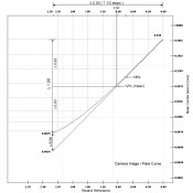
Here's an interesting concept. The average 7 1/3 stop (log 2.2) luminance range with diffused white highlights falling at 100% reflectance will have a range of around 0.92 logs falling above the metered point and around 1.28 logs falling below. What most people don't consider is what happens inside the camera. Development for an average scene isn't for the 7 1/3 stops. It is for 6 1/3 to 6 stops. Flare reduces the range that makes it to the film. This is actually the reason for the aim NDR being off with the Zone System compared to the LERs of paper grades. It's making a calculation based on no flare testing conditions and applying them to conditions with flare.

So there's 0.92 above and 1.28 below the metered point. The 1.28 is reduced by flare. One stop reduces it to 0.98 and average flare is between 1 and 1 1/3 stops which can reduce the difference more. So with one stop flare, 0.92 above and 0.98 below. The range of the for the shadow part is from 0.98 to 0.88 below. Flare balances the ranges and effectively makes the metered exposure the "middle" of an average scene in the camera. Below is an example of 1 1/4 stops flare.

Normal LSLR and Flare.jpg
 
Last edited by a moderator:

RobC

Member
Joined
Nov 5, 2007
Messages
3,880
Location
UK
Format
Multi Format
Thanks for finally explaining your approach. You're using a ten stop range and fitting it on the full range of the paper. Makes sense. What I think you are missing is the 7 1/3 stop calibration part. The range of the paper for the 7 1/3 stop test is shorter than the full range of the paper. The remainder of the 10 stop range falls outside "aim" density range for the 7 1/3 stop test willing the full range of the paper. The results are basically the same.

Are they? I don't think so becasue my CI, as I said is around 0.5. Standard dev is significantly higher. How you manage to say they are the same just doesn't make any kind of sense. They won't magically print the same way with same contrast on the same grade.

You have copied and studied adams numbers. I looked at them and ignored them and just use the practical evaluation (thats experiment to you) of reproducing his zone patches. The numbers I have given you are just read from the result of that evaluation. If I didn't have a densitometer I could still have arrived at exactly the same result. The densitometer is just useful for seeing what is happening and shortening the new film/dev/paper combo tests that I may do. That's as far as it needs to go.
 
Last edited by a moderator:
Joined
Jan 7, 2005
Messages
2,603
Location
Los Angeles
Format
4x5 Format
Are they? I don't think so becasue my CI, as I said is around 0.5. Standard dev is significantly higher. How you manage to say they are the same just doesn't make any kind of sense. They won't magically print the same way with same same contrast on the same grade.

Arguments from incredulity are pointless. Facts are facts whether you accept them or not.

I can show you how it works with a lot of graphs. Oh wait, I already showed you some. Take another look at the Holm's Preferred Zones (his paper is online). Plus I said basically. There are a number of variables that I'm unaware of in your testing. What is your aim NDR? How did you produce the test negative? I'm referring to the no flare test vs the camera image. That's one stop difference in effective luminance range. Adams made this mistake. Many people do. Before dismissing something, maybe you should work through it first. For me, I'm suspecting your testing or interpretation of the results are lacking something.

As for Adams, what I always found interesting is how his numbers could be so far off and yet work for most people. A NDR for grade 2 paper is not 1.30 but more around 1.05. People who do Zone System testing seem to be happy with it though. But is his numbers real? I found that the difference between the two systems was an illusion resulting from how the testing was done but mostly how the data was interpreted. Because ZS testing for development uses only two points of density, it's near impossible to discover the cause. Put it up on a film curve and it becomes evident.
 
Last edited by a moderator:

RobC

Member
Joined
Nov 5, 2007
Messages
3,880
Location
UK
Format
Multi Format
I can show you how it works with a lot of graphs, plus I said basically. There are a number of variables that I'm unaware of in your testing. What is your aim NDR? How did you produce the test negative? I'm referring to the no flare test vs the camera image. That's one stop difference in effective luminance range. Adams made this mistake. Many people do. Before dismissing something, maybe you should work through it first. For me, I'm suspecting your testing or interpretation of the results are lacking something.

Not interested. Like I said before, if you actually expose and print the zone patches and it produces exactly what you expect it to produce, then anyone telling you its wrong is not going to be taken seriously.
 

Xmas

Member
Joined
Sep 4, 2006
Messages
6,398
Location
UK
Format
35mm RF
Adams knew that overexposure of negatives increased the average number of acceptable prints!

Mees published it in his book with a graph showing this. So did Haist. It is in his book. And, before he became ill, he was tracing Adams route through the Grand Tetons reproducing many of the Adams shots on modern film, both B&W and color.

Adams could not afford to miss a shot.

So, he biased the zone system to call for about 1/2 to 1/3 stop overexposure in order to increase the number of usable negatives when he was out in the middle of nowhere and could not go back easily to re-create a scene. This was to help you all out, not create trillions of disturbed electrons discussing why and wherefore! :wink:

Simple as that!

PE
HiRon

Hope you are better.
Why then did Kodak people sponsor the ASA speed of Trix changing from 200 to 400 in 61 or so. They could have fired people instead?

Noel
 
OP
OP
Bill Burk

Bill Burk

Subscriber
Joined
Feb 9, 2010
Messages
9,160
Format
4x5 Format
Are they? I don't think so because my CI, as I said is around 0.5. Standard dev is significantly higher. You have copied and studied Adams numbers. I looked at them and ignored them.

If I were to explain what I think you have done, you appear to be developing to something like N-1 and using variable contrast paper to make up for any different subject luminance range that you encounter.
 

Photo Engineer

Subscriber
Joined
Apr 19, 2005
Messages
29,018
Location
Rochester, NY
Format
Multi Format
Because the curve shape became different. It used to have a bow in the middle, but they straightened it out. Also, they introduced the newer sensitization methods then and with the same grains got 1 stop more speed. This is called, btw, the speed grain ratio.

PE
 

markbarendt

Member
Joined
May 18, 2008
Messages
9,422
Location
Beaverton, OR
Format
Multi Format
No. The calibration means that with a spot meter, whatever you meter will give you a zone 5 placement.

Isn't that only true if we use that reading as the camera setting?

Does the zone system teach anybody to set the camera by using a direct reading without applying a correction or offset to find the camera setting?

The calibration point in the zone system is 0.1 right?

That's not zone V is it?

Isn't the difference between the meter reading and the speed point on the film curve defined by a specific spread in the zone system? Put another way, doesn't an offset (calibration) need to be applied to get the meter to read properly at zone V?
 
OP
OP
Bill Burk

Bill Burk

Subscriber
Joined
Feb 9, 2010
Messages
9,160
Format
4x5 Format
Isn't that only true if we use that reading as the camera setting?

Does the zone system teach anybody to set the camera by using a direct reading without applying a correction or offset to find the camera setting?

The calibration point in the zone system is 0.1 right?

That's not zone V is it?

Isn't the difference between the meter reading and the speed point on the film curve defined by a specific spread in the zone system? Put another way, doesn't an offset (calibration) need to be applied to get the meter to read properly at zone V?

If you put a Zone System sticker on your meter, you align Zone V with the main meter dial arrow.

Now there is nothing stopping anyone from choosing an Exposure Index that allows them to place shadows on Zone I with a direct reading. (Or picking any favorite Zone and making the Exposure Index to fit). But that's not your usual teaching.
 
Joined
Jan 7, 2005
Messages
2,603
Location
Los Angeles
Format
4x5 Format
This is the introduction from Safety Factors in Camera Exposures by C.N. Nelson. It outlines the reasoning for a proposed change in the sensitometric speed criterion.

"During the past three or four years, much criticism has been aimed at the safety factor involved in the use of American Standard exposure indexes' with exposure meters calibrated in accordance with American Standard procedures. A number of articles in photographic magazines have pointed out the penalties and disadvantages resulting from the use of too large a safety factor and have urged that a smaller safety factor be introduced by means of a revision in the American Standard for determining ASA exposure indexes for black-and-white negative films. The general spirit of these articles is illustrated by the following title of one of them: "ASA Exposure Index: Dangerously Safe."

A safety factor exists in a camera exposure whenever that exposure is greater than the minimum camera exposure that will produce a negative from which a print of excellent quality can be made. The ratio of the actual camera exposure to this minimum camera exposure is, by definition, the safety factor.

If a large safety factor is used, the negatives obtained will, on the average, be much denser than is required for making a high-quality print. A small safety factor means thinner negatives. The main advantages of negatives resulting from the use of a small safety factor are:

1. Easier focusing of enlargers
2. Shorter printing times
3. Less graininess in enlargements
4. Sharper pictures
a. Greater depth of field
b. Reduced subject-motion blur
c. Reduced camera-motion blur

Another advantage, found with the use of some films (especially if they have been overdeveloped), is that the shape of the part of the density-vs.-log exposure curve which is used for the thinner negatives is better than the shape of the part of the curve used for the heavily exposed negatives.

Because of these advantages, many photographers are convinced that the best camera exposure is one which is only slightly greater than the minimum camera exposure required for a print of high quality.

The main disadvantage of a small safety factor is that occasionally an underexposed negative will be obtained as a result of an error in camera exposure. The original purpose of the safety factor was to absorb such errors. Present-day experience with color reversal films, for which a large safety factor cannot be used, shows, however, that the number of underexposed pictures resulting from the use of a small safety factor is remarkably small. If a large safety factor is undesirable at the present time, why was it thought to be necessary when the American Standards for film ratings and exposure meters were first adopted in the 1940's? The first reason is that exposure meters, camera shutters, and lens apertures were not as accurate in the 1940's as they are in 1959. The second reason is that the camera-exposure latitude of black-and-white films was effectively greater in those earlier years, largely because the increase in print graininess with increase, in camera exposure was not as evident with the large cameras, large negatives, and small degree of enlargement or contact printing then commonly used. The great increase in the number of small cameras in recent years and the increase in the degree of enlargement has made the graininess problem more acute.

Many photographers have adopted the practice of giving less exposure than is indicated by the use of ASA exposure indexes with exposure meters. The American Standard indexes for black-and-white films are used by them only as a starting point for deriving a new kind of exposure index which is obtained by the simple procedure of doubling the Standard exposure index. This practice, of course, has the effect of cutting the safety factor in half, giving the preferred thinner negatives.

In recognition of this practice, a new Subcommittee, PH2-18, of the American Standards Association was formed a little more than a year ago for the purpose of revising the American Standard for Determining photographic speed and Exposure Index. Under the chairmanship of J. L. Tupper, .his Subcommittee has prepared a draft of a new Standard which will very likely be officially approved soon by the ASA Sectional Committee PH2 on Photographic Sensitometry (M. G. Anderson, Chairman), the Photographic Standards Board, and the officials of the American Standards Association. In this proposed Standard, the level of the numbers used for rating black-and-white films is approximately doubled. Such a change would have the fleet of reducing the safety factor to one half its present value.

There are no plans for reducing the safety factor by means of a change in the calibration formula or exposure meters because there are too many meters in existence with the present calibration and because the meters are also used for color film for which no change in exposure level or film rating is required or desired.
"
 
Last edited by a moderator:
OP
OP
Bill Burk

Bill Burk

Subscriber
Joined
Feb 9, 2010
Messages
9,160
Format
4x5 Format
Thanks Stephen,

I'm always interested in exploring the coincidence how several speed methodologies can all come close to agreeing with each other.

Probably because a committee was involved.
 

Xmas

Member
Joined
Sep 4, 2006
Messages
6,398
Location
UK
Format
35mm RF
If you put a Zone System sticker on your meter, you align Zone V with the main meter dial arrow.

Now there is nothing stopping anyone from choosing an Exposure Index that allows them to place shadows on Zone I with a direct reading. (Or picking any favorite Zone and making the Exposure Index to fit). But that's not your usual teaching.

Yes and that is the subtle point before 1961 your Weston meters calibration for zone 1 and zone 5 allowed you to use box ASA for HP3.

after 1961 you would be a stop out...

Back to starting post in this thread?
 

Ian Grant

Subscriber
Joined
Aug 2, 2004
Messages
23,241
Location
West Midland
Format
Multi Format
There's two or rather 3 different approaches to exposure being discussed in this thread.

There's the Theoretical approach of Stephen Benskin, the practical approach of the Zone Sstem and the Over-exposure approach of others.

Many of us are using the Practical approach of exposing for the shadows and developing for the high-lights, and the Zone System or BTZS. are just ways of putting this into practice. The Zone system doesn't mean over-exposure, it means more precise exposure and subsequent development adjusted to suit.

The over-exposure approach was largely used by mass market cameras with emulsions like Verichrom Pan & Selochrome Pan with their wide latitudes.

It's largely forgotten that the change in the B&W ASA standard increasing the nominal film speed took place at the time built in meters exposure meters became common place with many cameras, and the prices of hand-held meters was dropping substantially with Japanese imports (US/Europe etc)..

Ian
 

RobC

Member
Joined
Nov 5, 2007
Messages
3,880
Location
UK
Format
Multi Format
Isn't that only true if we use that reading as the camera setting?

what the meter reading is, is always a mid point after calibration.

Does the zone system teach anybody to set the camera by using a direct reading without applying a correction or offset to find the camera setting?
People interpret it in various ways according to how they want to use it. It should be remebered that Adams was using mostly sheet film and therefore exposing for shadows and then adjusting development for highlights on a sheet by sheet basis which makes sense. However, for roll film users it doesn't make any sense because you have many images on a roll all with different SBRs and you only get one development for all of them. In this case it makes a lot more sense to calibrate for a 10 Stop range because it covers 95% of all your SBRs on a roll, expose for the highlights and then adjust contrast in printing. If you are using sheet film then ignore anything I say and do it Adams way.

The calibration point in the zone system is 0.1 right?
That number is just a minimum recommended value in my opinion. Whether you actually get 0.8 or 1.5 is of little significance providing there is sufficient distance between zone 0 and zone 1. That difference according to me should be a minimum of 0.07. That value is the minimum required to show that the toe is coming up from being flat and that is the clue to the EI you should be using for the contrast range you are trying to calibrate to.

That's not zone V is it?
No it isn't zone V.
I think the confusion here is that previous posts are suggesting that zone V is 4 stops UP from 0.1. Well that is the target but meters don't use an offset from 0.1 UP from the bottom of the curve. They use an offset Down from the reading they take to a midpoint. This whole part of the discussion is so unecessary. If you do the zone patch test a la Adams (and me) then it will become very clear in an intuitive way without having to think about 0.1 or speed point. It only requires to think about lowering EI to get required shadow separation down to zone 0 and adjusting dev to get zone 10 to print as just white (or zone 9 as just a hint of tone before white which is the same thing in terms of required dev).

Isn't the difference between the meter reading and the speed point on the film curve defined by a specific spread in the zone system? Put another way, doesn't an offset (calibration) need to be applied to get the meter to read properly at zone V?
See above.

My aproach to all this is to use an intuitive non technical methodology which is just as accurate if not more so than a purely technical/scientific theory based approach. You need to make a choice which route you want to take because I am not going to start explaining my approach using charts, diagrams and log values. If you want to use those numbers then you should follow someone elses advice. If you are trying to compare my approach to a theoretical approach then you will fail becasue I don't use fixed targets and the results it gives may or may not fit some other peoples targets. I really don't care if they do or don't. I Don't think about them. I just use a practical test of actually doing photography to prove that what is being produced is what is expected. And if it is then the numbers are irrelevant. The proof is that if I point my meter at anything and place the exposure on a zone, then that is what is produced in the print. And I test that for each zone from 0 thru 10. Works for me. YMMV.

I would add that becasue all films curve shape varies, some with long shallow toes, some with very short abrupt toes, some with "average" toes, it means that any theoretical fixed value of 0.1 can't be right. Its not a fixed value but the theoreticians can't handle that concept. It also means the midpoint density and print value will vary from film to film and that both the shadow and the highlight densities will vary from film to film. And different papers response will vary in shadows, mid tones and highlights too. So when any theorist tells you about their target numbers, you should ask them to give you the numbers for the specific film, dev, and paper combination they are talking about with the exact times, temps, dilutions anc chemicals they are using so that you can be sure you're both swinging from the same branch.
 
Last edited by a moderator:
Photrio.com contains affiliate links to products. We may receive a commission for purchases made through these links.
To read our full affiliate disclosure statement please click Here.

PHOTRIO PARTNERS EQUALLY FUNDING OUR COMMUNITY:


Ilford ADOX Freestyle Photographic Stearman Press Weldon Color Lab Blue Moon Camera & Machine
Top Bottom