Consider taking a DSLR scan of a C-41 negative (raw, linear capture with no gamma correction). You get a negative that must be inverted.
However, it is well-known that due to the orange film base, simply inverting the RGB color channels will result in a positive with a teal cast. This is because the characteristic curves for each of the layers of the film are vertically offset. I've heard that scanners fix this by providing different exposures for the different color layers to compensate for the offset.
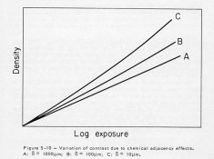
But examining the technical data sheet for Porta 400 (for example), I see that the curves are not merely offset, but also of different slopes. So simply the modifying the exposures for each layer won't produce true neutrals throughout the full range of luminances. See page 4 here: https://imaging.kodakalaris.com/sites/prod/files/files/resources/e4050_portra_400.pdf. They also differ in shape in the "shadow toe."
This leaves two possibilities. One, it was never the goal of C-41 film to produce true neutrals, and the slight color cast is an intentional part of the "film look," so the resulting cast doesn't matter (assuming the basic per-channel exposure adjustment described above). Or two, scanners are removing by doing something more sophisticated than just modifying exposure times per-color.
Which of these is true? And in either case, are details of the algorithms used by high-end scanners for color correction available anywhere? I suspect it's not much more than simple levels/curves/black-white point adjustments, but I'm curious how exactly those adjustments are being done so I can replicate them. Modifying the changes multiplicatively to simulate different per-channel exposures is trivially easy, but I'm not sure it's the whole story.
(Here I'm concerned with just matching the output of scanners, roughly. I'm aware that color can be "improved" by further tweaking and nonlinear curves fiddling, but I want to understand the fundamentals of the process first.)
However, it is well-known that due to the orange film base, simply inverting the RGB color channels will result in a positive with a teal cast. This is because the characteristic curves for each of the layers of the film are vertically offset. I've heard that scanners fix this by providing different exposures for the different color layers to compensate for the offset.
But examining the technical data sheet for Porta 400 (for example), I see that the curves are not merely offset, but also of different slopes. So simply the modifying the exposures for each layer won't produce true neutrals throughout the full range of luminances. See page 4 here: https://imaging.kodakalaris.com/sites/prod/files/files/resources/e4050_portra_400.pdf. They also differ in shape in the "shadow toe."
This leaves two possibilities. One, it was never the goal of C-41 film to produce true neutrals, and the slight color cast is an intentional part of the "film look," so the resulting cast doesn't matter (assuming the basic per-channel exposure adjustment described above). Or two, scanners are removing by doing something more sophisticated than just modifying exposure times per-color.
Which of these is true? And in either case, are details of the algorithms used by high-end scanners for color correction available anywhere? I suspect it's not much more than simple levels/curves/black-white point adjustments, but I'm curious how exactly those adjustments are being done so I can replicate them. Modifying the changes multiplicatively to simulate different per-channel exposures is trivially easy, but I'm not sure it's the whole story.
(Here I'm concerned with just matching the output of scanners, roughly. I'm aware that color can be "improved" by further tweaking and nonlinear curves fiddling, but I want to understand the fundamentals of the process first.)