Film Speed and Development Test (Excel spreadsheet supplied)

A window to art

D
A window to art

  • 0
  • 0
  • 12
Bushland Stairway

Bushland Stairway

  • 4
  • 1
  • 60
Rouse st

A
Rouse st

  • 6
  • 3
  • 101
Do-Over Decor

A
Do-Over Decor

  • 1
  • 1
  • 113

Recent Classifieds

Forum statistics

Threads
199,236
Messages
2,788,370
Members
99,840
Latest member
roshanm
Recent bookmarks
1
OP
OP
RalphLambrecht

RalphLambrecht

Subscriber
Joined
Sep 19, 2003
Messages
14,663
Location
K,Germany
Format
Medium Format
... Then I also thought it wouldn't necessarily be at the right colour temperature because unless it was pointing straight up it would pass light reflecting from the surrounding terrain. ...

Peter

That will be close enough. You want some of the surrounding terrain. Just the sky alone would be too high of a color temperature. Avoid early morning and late afternoon. You can also get some daylight bulbs for you light table, but I would not go through that expense.
 

PeterB

Member
Joined
Apr 3, 2005
Messages
644
Location
Sydney, Aust
Format
Medium Format
Hi Ralph,
the window didn't work ! Initially because the 'best' window position only let in afternoon sun which gave too much flare for my lens (yes I could have blocked that direct light into the lens but too much hassle again). The other problem is that with my lens it was impossibly difficult to get diffuse even light because the background wasn't sufficiently out of focus. So I then got a pane of glass from a photo frame and positioned it in a perfect place looking out to some trees, blue sky and a grey wooden fence, only to have the same problem with the background being too in focus. The other problem I then encountered was clouds moving into view changing the exposure levels !

Can you comment on my next plan which is to get a piece of bright white cardboard and use that as a backdrop reflecting direct sunlight through a pane of glass about a few metres away upon which I have taped the transmission step. The white card should be neutral (i.e. have no colour cast) (excluding effects of any optical brighteners fluorescing). I would then set my camera exposure to a grey card sitting in the same sunlight, or even use a hand held light meter to get the incident light level.
regards
Peter
 
OP
OP
RalphLambrecht

RalphLambrecht

Subscriber
Joined
Sep 19, 2003
Messages
14,663
Location
K,Germany
Format
Medium Format
Peter

I thought it was obvious not to photograph directly into the sun, my mistake.

... the window didn't work ! Initially because the 'best' window position only let in afternoon sun which gave too much flare for my lens ...

What is wrong with that window in the morning?
 

PeterB

Member
Joined
Apr 3, 2005
Messages
644
Location
Sydney, Aust
Format
Medium Format
I thought it was obvious not to photograph directly into the sun, my mistake.
I take responsibility ! It wasn't directly into the sun, the lens seems rather susceptible to flare so direct sunlight falling on it (but the sun itself not in the frame) is enough to noticeably reduce the contrast. I am using a Mamiya C330 with 80mm lens. I really need to get a lens hood as they are more subject to flare than the newer super multi coated lenses.

What is wrong with that window in the morning?

I touched upon this when I described how moving my portable pane of glass didn't work either. When I said the background wasn't sufficiently out of focus what I also meant to write was that the background has different colours throughout it and causes some of the Tx steps to be illuminated with light from the blue sky, others from some green trees and others from buildings or fences . None of those light sources are neutral enough in colour to preserve the original colour temperature of the direct sun which is about 5500K.

That is when I came up with the idea of using a white piece of card or paper to reflect direct sunlight back through a pane of glass a couple of metres away to which I affix the Tx step. I would ensure the white is behind the Tx step when viewed through the camera. Even if you still think I should use the natural environment can you comment on my idea 'cause in my mind it is superior to using some typical scene out of a window.

Rgds
Peter.
 

Lee L

Member
Joined
Nov 17, 2004
Messages
3,281
Format
Multi Format
To assure an even background for the step wedge, it's easiest to have a sheet of translucent perspex, opal glass, or a diffusion theatre gel behind the wedge. Backing with a clear piece of material (or nothing) will always produce the problems you're encountering and create an uneven background for the step tablet unless you have a very evenly lit uniform surface behind it. Make sure no direct shadows fall on the back of the diffusion material you use, as that will cause local 'density' differences.

To avoid flare, mask off the area around the step wedge + diffusion material with darker material, perhaps a larger piece of foamcore, and use the lens hood you mentioned. You could also use a 5000K fluorescent lamp in a clamp lamp reflector behind such a set up to make something consistent and usable at any time of day or night.

Lee
 
OP
OP
RalphLambrecht

RalphLambrecht

Subscriber
Joined
Sep 19, 2003
Messages
14,663
Location
K,Germany
Format
Medium Format
As Lee said.

... I really need to get a lens hood as they are more subject to flare than the newer super multi coated lenses. ...

You may want to do that before the test as flare will affect the test results. Alternatively, you could contact print the step tablet onto film, but that will eliminate flare altogether, which is not realistic.
 

PeterB

Member
Joined
Apr 3, 2005
Messages
644
Location
Sydney, Aust
Format
Medium Format
Thanks for your input Lee. If the perspex or opal glass have no specs with them, how likely are they to have a colour cast to them ? (I.e. not neutral?).
Lee what do you think about my suggestion to use a piece of white card as I explained in my last post above?

Rgds
Peter
 

Lee L

Member
Joined
Nov 17, 2004
Messages
3,281
Format
Multi Format
The difficulty with the piece of card is lighting it evenly. You're working with 1/3 to 1/2 stop steps in the wedge, and for usable results the card has to be lit very evenly and consistently over the entire area that the lens can see. That's more difficult to achieve than even backlighting for a diffusion material over a smaller area behind the step wedge.

There is a 'danger' that perspex or opal/milk glass will have some colour cast, and I don't know what's locally available in Oz. It might be less of a problem than you think, and is likely immaterial if you're shooting B&W film. If it appears anywhere near 'white' to the eye when you hold it up to the light, you're well within bounds for B&W. There are diffusion gels for theatre or photograpy that are color neutral. Check for a local theatre or photo studio supplier. Google "theatre supplies sydney australia". Lee and Rosco make suitable materials that are inexpensive. The supply store should have small swatch books for you to use in making a selection.

If you can't find a lens hood, just shoot through any size dark box that you can find/make to put between camera and the step wedge.

Lee
 

PeterB

Member
Joined
Apr 3, 2005
Messages
644
Location
Sydney, Aust
Format
Medium Format
The difficulty with the piece of card is lighting it evenly. You're working with 1/3 to 1/2 stop steps in the wedge, and for usable results the card has to be lit very evenly and consistently over the entire area that the lens can see.

Lee

Hi Lee, I would be illuminating the white card with direct sunlight outside. That should give ideal uniformity.
 

PeterB

Member
Joined
Apr 3, 2005
Messages
644
Location
Sydney, Aust
Format
Medium Format
As Lee said.
You may want to do that before the test as flare will affect the test results.

Thanks Ralph. I'll make a mock lens hood from cardboard and look to buy the real thing soon.
Peter. Even without sunlight hitting the lens there is bound to be a minor contribution from indirect light, so doing the test with the same configuration I intend to use the camera would be important , especially since this test is designed to compensate for contrast reduction due to flare.

Peter
 

Lee L

Member
Joined
Nov 17, 2004
Messages
3,281
Format
Multi Format
Hi Lee, I would be illuminating the white card with direct sunlight outside. That should give ideal uniformity.

That may not be the case when you're:
a) shooting through the window, which will add its own glare and reflections (and which seems to be the plan unless I'm misreading)
or
b) have the step wedge out in the sun as well, which would add glare and reflections off the face of the step wedge.

If you're shooting with the target in the sun, you may want to use a reflective step wedge. If it doesn't cover the range you need in one go, you can make bracketed shots to introduce the wanted greater or lesser densities.

I'm not really trying to be difficult, it's just that there are contingencies that we don't always take into account, and it's best (and in the long run easiest) to eliminate error up front rather than puzzling over where it came from later.

Lee
 

PeterB

Member
Joined
Apr 3, 2005
Messages
644
Location
Sydney, Aust
Format
Medium Format
Thanks Lee. Fortunately I'll be shooting outside with the white card in the sun and the transmission step wedge in the shade taped to a piece of glass. We usually have lots of sun in Sydney, but today (Sunday) has been overcast and a bit wet and I only have time to do this hobby on the weekends !
 

PeterB

Member
Joined
Apr 3, 2005
Messages
644
Location
Sydney, Aust
Format
Medium Format
Film Calibration test setup photographed and documented.

This Sunday arvo was the only free time I had to get back to this testing, but alas the cloud cover kept shifting. As a consolation, I spent the time photographing and documenting the test setup I had assembled.

http://goo.gl/wD4Kg
 

PeterB

Member
Joined
Apr 3, 2005
Messages
644
Location
Sydney, Aust
Format
Medium Format
Hi Ralph,

I developed one of the five rolls tonight (for 11mins). Before I develop the other ones I'm a bit concerned about two things

1. I used a 31 step Tx wedge. I did one development for 11mins and steps 24 through 31 (Tx densities 2.35 to 3.05) are all at the density of the film base+fog. This suggests my exposure might have been too long. Have I lost too much dynamic range in this test ? I exposed HP5+ using a nominal ASA of 200 (I know its 400, but I usually use it at 200 and your instructions say "You can use the manufacturer’s recommended film speed, since the actual exposure is not critical as long as it is within 1 stop."). I metered a grey card in the same direct sunlight as my white cardboard with a spot meter. My Mamiya C330 then required an exposure compensation ox x2.5 (1 1/3 stops) when shooting so close up, so I then put the ASA to 80 to address that). This resulted in me using f8 @ (1/250)s for all frames on all rolls.

2. I use XTOL 1+2 dilution which results in longer dev times. What set of dev times should I use instead of the the nominal ones you list (spanning 4-16min)?

rgds
Peter
 

PeterB

Member
Joined
Apr 3, 2005
Messages
644
Location
Sydney, Aust
Format
Medium Format
I developed one of the five rolls tonight (for 11mins). Before I develop the other ones I'm a bit concerned about two things

1. I used a 31 step Tx wedge. I did one development for 11mins and steps 24 through 31 (Tx densities 2.35 to 3.05) are all at the density of the film base+fog. ....

2. I use XTOL 1+2 dilution which results in longer dev times. What set of dev times should I use instead of the the nominal ones you list (spanning 4-16min)?

I think I can answer my questions. I looked at the example numbers in the spreadsheet and I was surprised to find the lowest two dev times (4 and 5.5 mins) both had very similar Tx densities (of about 0.05) for steps 24-31.

With increasing dev time, (esp up at 16mins in the example excel spreadsheet) those steps do increase marginally in density on the negs. So I think I will just need to extend my dev times out to perhaps 25 minutes.

I forgot that increasing the dev time does have a minor effect on the shadow density but primarily it is the exposure times which lock in the shadow density. Therefore I haven't wasted those steps on my Tx wedge, as most of them will play a part at higher dev times.


So now to estimate my remaining dev times.

From the example excel spreadsheet I fitted the points (1,4),(2,5.5),(3,8),(4,11),(5,16)=(n,t) to the general exponential curve t = m x EXP (a x n) :

t = 2.7968 x EXP(0.3466 x n)
with R² = 0.9992​

I then fixed a, passed it through my own point (2,11min) and solved for a new m, giving me
t = 5.5 x EXP (0.3466 x n)​

I then fixed a, passed it through my own point (2,11) and solved for a new m, giving me
t = 5.5 x EXP (0.3466 x n)

This gives me new points of (1,7.8),(2,11),(3,15.6),(4,22),(5,31.1)=(n,t)
The nominal dev time here for my choice of film, dilution, temp(20degC) and EI (200) is about 13mins.
I think my proposed dev times seem too long. So I'll recalculate this exponential equation with a two point fit to solve for both m and a after I do the next dev at say about 20mins.
 
Last edited by a moderator:

PeterB

Member
Joined
Apr 3, 2005
Messages
644
Location
Sydney, Aust
Format
Medium Format
Ok, so I had no need to complicate that formula above because I just noticed that those dev times in fact follow the simple geometric series t(n+1)=t(n)xSQRT(2). Which doubles every 2nd point, just like f-stops do !!
Anyway my initial exponential curve fit was pretty darn close and it still seems I will need to go out to about 32min dev time.
 

PeterB

Member
Joined
Apr 3, 2005
Messages
644
Location
Sydney, Aust
Format
Medium Format
Did my step wedge suffer from ambient light reflections during film testing ?

Well folks, I think I've got a problem. I've completed all the transmission density measurements of the 5 rolls of HP5plus 120 film developed in XTOL 1+2. You can see photos of my setup here.
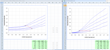
I've entered the raw data from my (frequently calibrated densitometer) into the spreadsheet supplied by Ralph over 5 months ago (and re-attached in xls format with my data) and I have two main concerns. Firstly though is a screen shot giving a comparison of my Family of Curves LHS to the default data in the spreadsheet (RHS) which was from Ralph's testing.
Film Test Evaluation.png

My first concern is that the lowest densities I get (in the toe) are way above 0.05, and none of them overlap in the toe area. According to my interpretation of the instructions posted by Ralph and WBM, they need to go below 0.17 so to determine the effective film speed (Zone 1.5=0.17). The fb+f density ranges from about 0.1 to 0.15, so I think this means the film was fixed adequately.

So why do I have too much transmission density in the toe ?

The other concern I have is that the highest density measured is only 1.5, whereas Ralph's was 2.1 It would seem I'm missing a good chunk of dynamic range here.

Should I expect a greater transmission density than 1.5 for a relative log exposure of 3.0 ?​

The possible explanation for the added toe density might be reflections from ambient light as I did this outside. I did shield one side of the path from camera lens to the transmission step wedge using opaque card to hopefully eliminate reflections. The side I shielded was the side the sun was on. I know Lee warned me about reflections, but is this truly the side effect, or is this response typical of my film+dev combo ? I did use a lens hood to reduce flare.

rgds
Peter

PS Ralph. I hope you are recovering OK. Take it easy if that's possible.
 

Attachments

  • FilmTestEvaluation of Ilford HP5plus 120 in XTOL 1+2.xls
    214 KB · Views: 119
Last edited by a moderator:
Joined
Jan 7, 2005
Messages
2,634
Location
Los Angeles
Format
4x5 Format
There looks to be two things going on with your test. First, you have under exposed the step tablet. That's what is causing the large flat line. You have yet to overcome the inertia of the film. Second, you really need to contact the step tablet. It eliminates many variables and makes it easier to track down problems. In this case, the problem looks like flare. The flat line portion should equal the Fb+b as there hasn't been enough exposure to produce density differences. The density above Fb+f has to come from non-image producing exposure. A light leak is one possible answer, but based on the description of the test, the large white background is at fault. Contacting eliminates flare. There's a reason why things are done a certain way. Don't try to reinvent the wheel.
 

Bill Burk

Subscriber
Joined
Feb 9, 2010
Messages
9,329
Format
4x5 Format
Stephen's right, there has to be tons of flare in your setup.

The difference between tungsten and daylight on film has got to be far less than the difference between your graph and ideal. You may be working too hard to rule out a variable that is significant, but not as gross.

At the very least, build a dark chamber for the area in front of the camera and mask out the step tablets with black construction paper to minimize flare. But I would second Stephen's recommendation to make your tests with the step wedges in contact with film.
 

PeterB

Member
Joined
Apr 3, 2005
Messages
644
Location
Sydney, Aust
Format
Medium Format
Stephen and Bill, thank you for your suggestions. I totally forgot about the flare from the large white card I used. I was only considering flare caused directly from the sun !! I won't make that mistake again.

If I contact expose the step wedge with my film it will be fiddly as I'm using 120 roll film not sheet film. Also won't that eliminate any inherent contrast reduction caused by my Mamiya's 80mm lens? I assumed one of the points of this test was to incorporate one's equipment in the light path.
What do you think about the idea of using a light box and taping the step's border with black to eliminate flare?
My original reason not to use it was its unknown colour temperature, but as Bill points out that is minor compared to the other problems I introduced.

When I expose the step wedge again I will increase the exposure. I had followed closely all the instructions but at least now I have a baseline to help me work out how much more exposure I need.
 

Bill Burk

Subscriber
Joined
Feb 9, 2010
Messages
9,329
Format
4x5 Format
Hi PeterB,

It'll be better but you'll still have flare. The clear steps will light up the whole works giving the denser steps some illumination.

Testing the camera system including flare was often taught in Zone System workshops. There is great value to be had learning the effects of exposure and development in a short time. I have a hunch you may have just learned that lesson.

The practice of camera system tests is often discouraged these days because it includes too many variables and you won't know what the results mean.

Film tests in contact with test strips will get you the response of film to light and development. Even if you do not have an accurate sensitometer, with a consistent exposure you'll get good graph shapes. The graph that matches the ASA gradient will give you the benchmark for speed, you can look down at 0.1 density and work backwards (trusting the manufacturer's box speed).

This will give you numbers to put in Ralph's spreadsheet for your film and development technique and times.

You can test for flare separately from the test for film speed. The book Beyond the Zone System describes a black box. Basically a cardboard box painted black inside with a hole in front. A coffee can painted black is another one. The idea is you shoot this in your typical scene and theoretically it should be perfectly clear on film because it is pure black. But flare will give it some density.

You kind of already did a flare test.
 
Joined
Jan 7, 2005
Messages
2,634
Location
Los Angeles
Format
4x5 Format
What do you think about the idea of using a light box and taping the step's border with black to eliminate flare?

Masking off any stray light from a light box will improve the results, but basically you are testing for too many factors. If you want to test the film, test only the film. If you want to test the lens, test only the lens. If you have too many variables, it's near impossible to attribute the influence of any particular variable.

There isn't a single flare factor for a given lens. 80% of flare comes from the subject and it varies depending on the luminance range and tonal distribution. A small black area with a light surround will have greater flare than visa-versa even though they have identical luminance ranges. So it isn't really beneficial to do a film test using a camera if testing for flare is your goal. The results will only reflect that specific situation and it will limit the usefulness of applying the data to other situations.

A key reason to contract the step tablet is to eliminate flare from the mix so that you can ascertain the proper film characteristics. Flare is then factored in at the evaluation stage. For instance, the flare factor for a statistically average scene is around one stop to 1 1/3 stop with modern lenses. If you are attempting to determine the film density at a seven stop scene luminance range you simply take the seven stops and subtract flare to give you the illuminance range to use when evaluating the film curve. For one stop of flare, the film effectively has a six stop illuminance range for a seven stop luminance range.

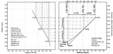
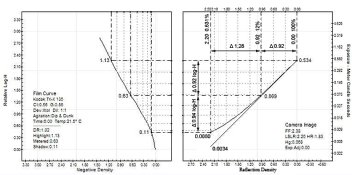
Conceptually, you can think of testing as having two different kinds of exposure. There's the sensitometric exposure that produces the characteristic curve and the photographic or camera exposure that juxtaposes the luminance values of the subject on top of the film curve and is what we use to evaluate the results for a given set of conditions. Film speed and camera exposure of EI should also be viewed in a similar manner.

I've attached an two examples to help illustrate this concept. One example has a one stop flare factor and the other a 1 1/3 stop flare factor. Notice how the subject's values are changed in the camera (Quadrant 1) and are placed on top of a fixed film curve (Quadrant 2). The straight line in Quadrant 1 represents a zero flare model and you will notice how the exposure would fall further into the film's toe without the presence of flare. The resulting negative density ranges from the two examples will be different, but in neither case does the film curve change.
 

Attachments

  • One stop flare example.jpg
    One stop flare example.jpg
    116.2 KB · Views: 130
  • one and a third stop flare.jpg
    one and a third stop flare.jpg
    118.2 KB · Views: 129
Last edited by a moderator:
Joined
Jan 7, 2005
Messages
2,634
Location
Los Angeles
Format
4x5 Format
Bill,

I actually did a similar test once using the Davis black box. I cut out four different squares to surround the hole in the black box and made four identical exposures. The squares were white, black, gray, and a mixture of all three. I've attached the results.
 

Attachments

  • Flare test.jpg
    Flare test.jpg
    64.4 KB · Views: 133

PeterB

Member
Joined
Apr 3, 2005
Messages
644
Location
Sydney, Aust
Format
Medium Format
Thanks again Bill and Stephen. That dreaded flare rears its head everywhere ! Before I read your last posts I was thinking to myself, how on earth can I hope to properly expose and develop a scene with lots of light areas in it (either in or just outside the image) if that is going to contribute to contrast reduction through flare. Clearly as you point out I need to test for that separately with my (non modern, (single coated ?) lens) as well as make assumptions/adjustments based on how my scene's brightness levels are weighted/distributed.

I will do a bit of reading up on doing the contact method, I think the main thing I need to determine now is how much exposure to give it and by what method (as I won't have a shutter to accurately time anything. The exposure must be at least 5-10 seconds if I use my enlarger timer. I was thinking of using that timer to switch a the light from a distant globe in the same room perhaps (my enlarger light would be way to bright for that many seconds worth of exposure).
 
Joined
Jan 7, 2005
Messages
2,634
Location
Los Angeles
Format
4x5 Format
Peter,

If you don't want to contend with reciprocity failure, you need to keep the exposure under a second.

BTW, a good way to calculate aim CI is:

desired negative density range / (log subject luminance range - flare)

Example: 1.05 / (2.2 - .40) = 0.58

Also, flare tends to increase as the scene's luminance range increases and decreases as the scene's luminance range decreases. It averages a 1/3 stop increase or decrease in flare per one stop change in luminance range.
 
Photrio.com contains affiliate links to products. We may receive a commission for purchases made through these links.
To read our full affiliate disclosure statement please click Here.

PHOTRIO PARTNERS EQUALLY FUNDING OUR COMMUNITY:


Ilford ADOX Freestyle Photographic Stearman Press Weldon Color Lab Blue Moon Camera & Machine
Top Bottom