Build a shutter tester for Focal Plane shutters - Cheap, Easy & it Works

Untitled

A
Untitled

  • 1
  • 2
  • 251
Blood Moon Zakynthos

H
Blood Moon Zakynthos

  • 0
  • 0
  • 533
Alexandra

H
Alexandra

  • 2
  • 0
  • 640
Prison

D
Prison

  • 2
  • 1
  • 732

Recent Classifieds

Forum statistics

Threads
199,772
Messages
2,796,380
Members
100,033
Latest member
awshaw
Recent bookmarks
0

Kotanov

Member
Joined
Aug 4, 2025
Messages
4
Location
Bulgaria
Format
Digital
Hi, first of all apologies. Photrio seems not to be sending me an email when somebody posts or PMs, so unless I check in, I cannot see new posts.

Thank you for taking the time to post the issue and more importantly, the solution.

As for the sensor board issue. Ideally I would like one in my hand to look at, or at the least a photo of the component side.

But from what I can surmise by looking at the photos and comparing it to an original pcb, it seems somebody has copied the original pcb layout, changing it slightly, muffing it up, making two errors.

This board has a slightly different layout to the original, the solder pad circled in red has been moved up.

It seems that this solder pad is not connected to any pcb track.
Assuming on the other side, it is the pullup resister, then as correctly shown in the OPs photo, it should be connected to the pad below.

The second error that I can see on the 'good board' (but it looks ok on the 'Bad' board photo), the pcb track from the smoothing capacitor just stops and does not continue to the top-left.


In the 'Good' photo below, I have highlighted in yellow, the two errors, where wire links require soldering.

Why the pcb design has changed, I have no idea. I have two variations in my collection, the pcbs are identical, but the screen printing is slightly different.
Whether there is just one pcb manufacturer of this board & they have slightly changed it & goofed up, or another company has decided to copy the design, who knows.


View attachment 406078

Hello,
I was away for a bit and had no time to reply and play with the tester. I have attached photos of both sides of the boards, on mine the only issue seems to be the first connection to the resister the others are ok, I just tested them. So they appear to work with the added connection.
I will probably buy more boards but from different seller after I do some more testing and will build better laser/sensor stand

Oh and the activation code you send me does not seem to work, so please advice what to do.

Greetings.
 

Attachments

  • 20250827_230254.jpg
    20250827_230254.jpg
    597.8 KB · Views: 21
  • 20250827_230332.jpg
    20250827_230332.jpg
    318.7 KB · Views: 21
OP
OP

Niglyn

Member
Joined
Feb 26, 2022
Messages
446
Location
Surrey, UK
Format
Analog
I started doing some due diligence by reading the first 4 pages of this thread.27 more to go I suppose. I've never used Github, but just went on to do a search by typing in "shutter tester". Apparently there's 46 of them. No way I can know which one is the one in this thread. Also, there seemed to be a situation where only the user Niglyn has tthe code needed to program it. For what it's worth, I've restored a LOT of ham radio gear, oscilloscopes, signal genrators, R to R tape recorders, and lots of other things. Also I'm pretty good at Freecad and have a couple nice 3D printers. One has a .2mm tip that can print extremely high detail in PLA. So I'm sure I can contribute stl's to the forum for a nice cabinet for this device. Thank you.

HI, well you have the choice of 46 if you want to build one :surprised:) or look at those listed on ebay etc for built units. Should keep you busy comparing them all :surprised:)

Here is the link to mine.

The complied code for The Shutter Tester is free and on Github.

A passkey is required, which is given free. Details are in the user guide.
 

F4U

Member
Joined
Jan 15, 2025
Messages
633
Location
Florida
Format
8x10 Format
HI, well you have the choice of 46 if you want to build one :surprised:) or look at those listed on ebay etc for built units. Should keep you busy comparing them all :surprised:)

Here is the link to mine.

The complied code for The Shutter Tester is free and on Github.

A passkey is required, which is given free. Details are in the user guide.

Thank you. but before I go through all that, I had recently bought one of these off ebay. It SEEMS to be doing OK, but how can I really know? Is the one in this thread really any better? See attached photo
 

Attachments

  • Screenshot_2025-08-28_16-25-20.jpg
    Screenshot_2025-08-28_16-25-20.jpg
    234 KB · Views: 37
  • Niglyn
  • Deleted
  • Reason: too much waffle
OP
OP

Niglyn

Member
Joined
Feb 26, 2022
Messages
446
Location
Surrey, UK
Format
Analog
I try to refrain on commenting or critiquing other shutter testers and other shutter tester designs available. Queries about their design & products should of course be addressed to them. I certainly do not wish to upset anyone or get into battle over whose is more accurate or whose is best.

All of details of my tester & compiled code are freely available, including the user guide detailing all of the functionality, I'm happy to answer questions and discuss my tester, camera repair and testing in general.

The issue of how to accurately measure focal plane shutters, how to go about doing so and the problem with sensor width has been discussed & debated in magazine articles going back to the 60s. Many of these articles have been re-published and can be found on-line.

Kosmo-photo has an article on their web site discussing this exact issue of sensor width influencing readings and warning against using inaccurate testers.
They have a very old drum tester, which is a revolving drum with slots and a light source.
This is similar to the old way of using an old CRT television.

The issue I see, and the same trap I initially fell into, not understanding that a focal-plane shutter is a slot (formed by the opening and closing curtain) and this gap determines exposure or shutter 'speed' and so a simple sensor cannot be used to measure the moving curtain.

This gap cannot be measured with a single sensor, as sensors 'turn on' and 'turn off' at different points on their surface.
For example a sensor might turn on when it sees the first teeny chink of light, when the senor is uncovered by only 0.2mm.
It will then turn off, when most of the sensor is almost fully covered, maybe 0.9mm. This is called hysteresis.

There may be a device out there, using two sensors in a single package, accurately aligned so one measures on, the other off, on the exact same plane, but I have not found such a device, searching RS & Farnell catalogues.

What I have seen in more than one place, including a product page, is a shutter tester tester. This uses an LED, driven by an Arduino, which flashes at 1/125s.

This in turn is pointed at the shutter tester, which then reads 1/125s. This then 'proving' their shutter tester design is accurate.

This is quite alarming as it shows the person does not understand how a focal-plane shutter works or the issues in measuring the shutter 'speed'.

Of course the tester will read 1/125s as the whole sensor is illuminated by the LED for exactly 1/125s.
What is not realised, is the moving curtain of the shutter does not instantly open & close, like an LED turning on & off.
 
Last edited:
OP
OP

Niglyn

Member
Joined
Feb 26, 2022
Messages
446
Location
Surrey, UK
Format
Analog
An extract from a kosmo foto article, detailing shutters and the testing of them. I agree with every word, which is why the multitude of DIY shutter testers available, either to purchase or make oneself, are simply inaccurate at higher speeds.

"The real switch of the sensor from light to dark comes not at the actual time of the curtain moving against the sensor, but at time when the actual light stream is reduced to what the sensor believes is dark, and sensor may have some inertia too. Also, the point of switching from light to dark is not the same as the point of switch from dark to light. So, sensors have their own characteristics that affect metering.

In this case we can reach an important conclusion: the shorter metered time, the more influence physical features of the device has on accuracy. In other words, the shorter the time measured, the more likely there will be an error in the metering".


And for leaf shutters, things get worse for leaf shutters

"And finally the case of the shortest speed. Leaves open – leaves close. No delay. Shutter did not stay in the fully opened position. And in this case the result of metering is not dependent on the shutter! The result is dependent on device characteristics only! In Picture 5 I show three possible levels of the switching sensor: L1, L2, L3. Using those levels we can get three values of the metered time t1, t2, t3. And all the values will be correct. But they will reflect not the shutter speed, but the internal setting of the metering device".

Screenshot-2020-12-09-at-09.16.46.png


"And now some final conclusions:

  • The metered value always contains an error.
  • With a faster shutter speed, the margin of error in the metered value is greater.
  • Never use as the correct value the metered value based on the fastest shutter speed, especially for leaf-shutter cameras"

Additional comments by niglyn.....
Thank heavens we have my The Shutter Tester, cheap, simple and the most important factor:-
It works!

Errors detailed above are mathematically computed in my shutter tester and the results shown are the calculated exposure values, thus giving an accurate result.
 
Last edited:
OP
OP

Niglyn

Member
Joined
Feb 26, 2022
Messages
446
Location
Surrey, UK
Format
Analog
Here is another article from Kosmo Foto discussing testing of camera shutters and how it is not so simple to test them!
Hopefully a copy & paste works.

Link to original, which maybe easier to read.

How to get the best from a smartphone light meter​

By
Stephen Dowling
-
09/12/2020
7857

0
KMZ Iskra (Pic: Oleg Khalyavin)
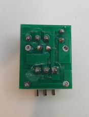
Leaf shutters like the one in this KMZ Iskra add extra complexity (Pic: Oleg Khalyavin)
By Oleg Khalyavin
Lately, shutter testers are becoming very popular for using on old classic films cameras. Such popularity resulted from the recent availability smartphones, that allow the development of metering devices using software applications. In this case, an input device is used as a light sensor connected to the phone’s microphone input connector. And what were previously specialised pieces of hardware costing at least $100 are now software solutions almost free and available to almost anyone.
Now many people try to check shutter speeds this way, and even adjust shutters.
However, let’s try to think how this metering process works. How do modern simple shutter testers with one light sensor calculate the metering, and how does the tester get a final result: digits on the smartphone screen?
Let’s look at two types of shutters – the process of metering shutter curtain speed and the shutter speed in a lea shutter camera.
First up – shutter curtains! In an ideal world both curtains (the first opening, and the second closing the frame window) travel at an infinitely fast speed. In this case, we need to meter the time between opening and closing the frame window. But this is not how things work in the real world. Really curtains need some time for opening and some time for closing. It makes an error in metering.
Lightmeter display (Pic: Oleg Khalyavin)

Of course, we can ignore this error and just meter the time between getting light to the light sensor and losing that light. It almost exactly represents the time it takes to open the frame at long speeds. Let’s determine the phrase long time speeds as a set of speeds longer than sync speed of the shutter. So, long time speeds are the speeds with delay between full opening of first curtain and starting of move of second curtain.
The diagram on Picture 1 shows the quantity of light reaching the film while the shutter works on long time speed. The diagram shows the period of the opening frame (it’s uneven, because the curtain has inertia and travels with changing speed), the period of delay and the period second curtain closes the frame. What does the shutter tester meter in this case? The time between two events – the opening and closing in the dot of the light sensor. What does the metered time show? An almost accurate time of the shuttering opening with potential error for uneven travelling of the curtains. But we can overlook this error because time of delay is longer than the time curtains move. Nice result! It’s working!
Screenshot-2020-12-09-at-09.02.42.png

Picture 1. Diagram of light for long time speed of curtains shutter
But it all changes if the shutter works at a faster speed (short time speed). In this case, the second curtains start moving while the first curtains are moving too. In fact, both curtains move independently at the same time. In the old classic Leica, the shutter curtains are not linked to each other. In the old Contax rangefinders, the shutter curtains are linked but softly, by friction over the silk ribbons. In the later Zenit SLRs, the shutters have a hard link between the curtains while moving.
In shutters with independent curtains, there is the possibility of changing of the width of the gap between curtains while they are in motion. And the speed of motion changes too. In shutters with a hard gap the width of the gap is constant, but the speed of motion may vary. So, time metered by a shutter tester may be different, depending on placement of the light sensor inside the frame. The diagram of the light is shown on Picture 2. All the same, as in the previous case, there is not any period of delay.
Screenshot-2020-12-09-at-09.07.21.png

Picture 2. Diagram of light for short time speed of shutter curtains
It would seem that with reasonable accuracy of metering we can neglect changing the width of the gap and its unstable speed. But while we try to meter short time we are have another problem: sensitivity of the light sensor and levels of switching between light and no light.
Let’s see the characteristic of sensitivity of some theoretical light sensor in Picture 3. Unfortunately, we don’t have any ideal sensor with ideal characteristics. In real life, sensors have a curve of dependence of resistance, for example, from light. For definition of the state “light” or “no light” we must choose a point, which is considered the border between light and darkness. Usually, developers select a point on the most inclined part of curve for more accuracy in working with the device. But developers may select any point of division light-dark for any reason of their own.
The real switch of the sensor from light to dark comes not at the actual time of the curtain moving against the sensor, but at time when the actual light stream is reduced to what the sensor believes is dark, and sensor may have some inertia too. Also, the point of switching from light to dark is not the same as the point of switch from dark to light. So, sensors have their own characteristics that affect metering.
In this case we can reach an important conclusion: the shorter metered time, the more influence physical features of the device has on accuracy. In other words, the shorter the time measured, the more likely there will be an error in the metering.
Screenshot-2020-12-09-at-09.12.17.png

Picture 3. Photoresistor characteristics. Dependance resistance from light.
And now let’s consider the leaf shutter. Just like shutter curtains, we will view two cases: long time and short time shutter speeds. Important note, the shortest speed for a leaf shutter is its sync speed. we’ll consider long time speeds like all speeds, except the fastest one. (In some shutters like the Compur-Rapid, the fastest speed setting uses an additional load spring, so for this shutter the short time speeds are the two shortest speeds). In other words: the long time speed is the when the shutter speed governor is employed.
Screenshot-2020-12-09-at-09.14.33.png

Picture 4. Diagram of light for long time speed of a leaf shutter
In a leaf shutter, a big role is played by the inertia of the leaves. Leaves from the closed position start moving, then accelerate, then stop and begin moving back. That’s why for a lot of time when the shutter is open, the light stream is partially blocked by the leaves.
In case of long time speed: leaves open – pause – leaves close. See the diagram of light shown on Picture 4. The longer the time, the longer the delay between opening and closing. If the sensor characteristics do not take this into account, we are likely to meter the shutter speed with some error. The size of the error depends on the metering device and not the shutter. But with reducing time of delay part of error in result is rise. Shorter time – less accuracy of meter.
And finally the case of the shortest speed. Leaves open – leaves close. No delay. Shutter did not stay in the fully opened position. And in this case the result of metering is not dependent on the shutter! The result is dependent on device characteristics only! In Picture 5 I show three possible levels of the switching sensor: L1, L2, L3. Using those levels we can get three values of the metered time t1, t2, t3. And all the values will be correct. But they will reflect not the shutter speed, but the internal setting of the metering device.
Screenshot-2020-12-09-at-09.16.46.png

Picture 5. Diagram of light for short time speed of leaf shutter
And now some final conclusions:
  • The metered value always contains an error.
  • With a faster shutter speed, the margin of error in the metered value is greater.
  • Never use as the correct value the metered value based on the fastest shutter speed, especially for leaf-shutter cameras
And lastly: I do not say that meters are useless. No, shutter testers are very useful devices if you understand the principles of how they work and use a correct method of metering. It is very important to use a proper light source. All metered values, if you compare those values, should be taken with the same light source. That way, you’ll be able to check the ratio of metered values to each other.
But please understand, metered values are not absolute and may be different from reality. Different meters may show different results on the same camera at short speeds. It does not mean the device is working incorrectly, it means different meters use different internal settings for light levels. On long speeds, all meters show almost the same results.
So, use a meter for checking your camera, but do not try to get special digits on device display. Final checking of camera is best done with the best light sensor – film!


© All material copyright Kosmo Foto except where explicitly stated. No part of this website can be reproduced without written permission.
 

Attachments

  • 1756478051048.png
    1756478051048.png
    101 bytes · Views: 12
  • 1756478051033.png
    1756478051033.png
    101 bytes · Views: 10
  • 1756478051005.png
    1756478051005.png
    101 bytes · Views: 9
  • 1756478050986.png
    1756478050986.png
    111 bytes · Views: 9
  • 1756478050970.png
    1756478050970.png
    111 bytes · Views: 9
  • 1756478050955.png
    1756478050955.png
    111 bytes · Views: 11

ronron

Member
Joined
Aug 10, 2025
Messages
12
Location
france
Format
35mm
hi Niglyn, i've just finish it today, can you send me the code? thanks
code.jpg
 
OP
OP

Niglyn

Member
Joined
Feb 26, 2022
Messages
446
Location
Surrey, UK
Format
Analog
Hi, here are some photos of the pcb I am working on.

It replaces the screw-terminal breakout board.

TFT plugs in one side of the board, ESP32 dev board on the other.

All the connections between TFT and ESP32 are on the pcb, which simplifies the wiring.

Other connections will be bought to the edge of the board on screw terminals.
test2back.jpg
test2front.jpg
 

tiasmaaa

Member
Joined
Mar 12, 2025
Messages
15
Location
Switzerland
Format
35mm
hello!

I'm currently servicing Mamiya RB lenses, and so im trying for the first time the shutter tester with leaf shutter.
I took measurement and from the center of the iris and the edge, there's 14mm. Perhaps in the settings of your shutter tester, the sensor space can't be set under 20mm. Is it possible to make a small update for that ? Or maybe is it simple to change in the code ?

Thank you !

And btw, still no one made a good 3d print for sensor/laser ? I have no 3d printer and no skills making plans... But im getting tired of my Lego cheap system ahaha.
 

ronron

Member
Joined
Aug 10, 2025
Messages
12
Location
france
Format
35mm
i also use a tree position switch to get vertical or horizontal with schottky diode on each receiver, i'm going to try it tomorrow
 
OP
OP

Niglyn

Member
Joined
Feb 26, 2022
Messages
446
Location
Surrey, UK
Format
Analog
hello!

I'm currently servicing Mamiya RB lenses, and so im trying for the first time the shutter tester with leaf shutter.
I took measurement and from the center of the iris and the edge, there's 14mm. Perhaps in the settings of your shutter tester, the sensor space can't be set under 20mm. Is it possible to make a small update for that ? Or maybe is it simple to change in the code ?

Thank you !

And btw, still no one made a good 3d print for sensor/laser ? I have no 3d printer and no skills making plans... But im getting tired of my Lego cheap system ahaha.

Hi, I have just changed the code so you can set a sensor width down to 10mm. It is on github 4_01_01b

Please be aware the leaf testing functionality has only been tested on my home-made leaf shutter, so please do not rely on the results.

I have been making pcbs today, to replace the breakout board in The Shutter Tester.
All the TFT wiring is now on the pcb, so cuts down on the spaghetti.

Decided to stick with screw terminals for the other connections, so the builder can choose connectors & layout that suits them.
Providing they work ok, will sell them, together with all the header & screw connectors, for cost price.

So the above is why I have not got round to 3d printing yet :surprised:)

There are a few 3d files floating around but I'm not aware of anyone publishing a complete project.

Please let us know how you get on testing leaf shutters.
 
OP
OP

Niglyn

Member
Joined
Feb 26, 2022
Messages
446
Location
Surrey, UK
Format
Analog
I can't get any signal on 25 33 and 32 weird!

HI, they are inputs, so you will not see much on them with a volt meter or scope.

Go into the alignment utility to see them change state.

Use a 10k resister in series to connect one of the pins to 3V (don't connect 3V directly).

The alignment utility will then show a steady state.

Remove the resister & 3V and connect directly to 0V
The alignment utility will now show the opposite state.

Note, with nothing connected, the input is floating and could show anything & will be unstable.
 

ronron

Member
Joined
Aug 10, 2025
Messages
12
Location
france
Format
35mm
Thanks Niglyn there is no change, the only things i see, it is that i have always 3.15v even when there is nothing connected, if i put the laser on, i get 3.10v and 3.15v when i cut the signal between led and laser
 

ronron

Member
Joined
Aug 10, 2025
Messages
12
Location
france
Format
35mm
with the 10k it's ok it 's changing on the screen, something goes wrong between laser and esp
 
OP
OP

Niglyn

Member
Joined
Feb 26, 2022
Messages
446
Location
Surrey, UK
Format
Analog
with the 10k it's ok it 's changing on the screen, something goes wrong between laser and esp

Hi, not the laser, but the sensor.

Laser connects only to 3V and 0V.

Sensor board connects to 3V, 0V and the centre connector to the ESP32 pin

Please check your sensor board. There is a faulty batch that has one leg of the pullup resister not connected correctly.

Look at post 764 and 768.
 
OP
OP

Niglyn

Member
Joined
Feb 26, 2022
Messages
446
Location
Surrey, UK
Format
Analog
PCB update,

Hi everyone,

I have designed a new pcb to replace the existing breakout board.

The TFT screen plugs in one side of the pcb and the ESP32 board on the other.

All of the TFT wires, including touch-screen are routed directly on the pcb, this cuts down on and simplifies the wiring.

All of the other connections are made via screw terminals, in the same way as the existing breakout-board.

Additional 5V, 3V and 0V screw terminals have been added. This allows for neater wiring and negates the need for extra terminal blocks to connect the 5V 3V & 0V wires.

The new pcb is 100mm long. This is 8mm shorter than the TFT. Unfortunately adding the extra 8mm would treble the price of the pcb.
So whilst the top two mounting holes line up, the bottom two do not, so the builder will need to make two short extension links from an offcut of plastic.

Price is as cheap as I can possibly make them, ordering in batches of 10.
They will be £5.00 or 6 euro plus postage. (based on today's component prices)
This includes the black header sockets for TFT & ESP32 and all the green screw terminals.

Alternately, the pcb can be ordered directly from the manufacturer.

Will post an update when the first one is up & working.

Here is the board, note the green sockets shown here are not the final ones to be used, which will be the traditional screw terminals as used on the existing breakout board.


shuttertester3_5mm_100mmboard.jpg
 

tiasmaaa

Member
Joined
Mar 12, 2025
Messages
15
Location
Switzerland
Format
35mm
Hi, I have just changed the code so you can set a sensor width down to 10mm. It is on github 4_01_01b

Please be aware the leaf testing functionality has only been tested on my home-made leaf shutter, so please do not rely on the results.

I have been making pcbs today, to replace the breakout board in The Shutter Tester.
All the TFT wiring is now on the pcb, so cuts down on the spaghetti.

Decided to stick with screw terminals for the other connections, so the builder can choose connectors & layout that suits them.
Providing they work ok, will sell them, together with all the header & screw connectors, for cost price.

So the above is why I have not got round to 3d printing yet :surprised:)

There are a few 3d files floating around but I'm not aware of anyone publishing a complete project.

Please let us know how you get on testing leaf shutters.

thank you so much ! that was fast.
actually it looks working. Maybe i can compare with audacity method, but i think yours is more accurate.
i'm testing mamiya rb lense, i actually have no idea if the lense should have good shutter speed or not.
i made a first test, based on iso 516 tolerence for front shutter.
that's the result :

Marked speed Nominal_ms Ev_limit ISO_min_ms ISO_max_ms Measured_ms Status Δ vs nominal % |Δ| in Ev
1/400 2,50000 0,45 1,83011 3,41510 4,55000 Out of tol 82,00% 0,86394
1/250 4,00000 0,45 2,92817 5,46416 5,03000 OK 25,75% 0,33056
1/125 8,00000 0,3 6,49802 9,84916 6,20000 Out of tol -22,50% 0,36773
1/60 16,66667 0,3 13,53754 20,51908 11,80000 Out of tol -29,20% 0,49818
1/30 33,33333 0,3 27,07508 41,03814 28,00000 OK -16,00% 0,25154
1/15 66,66667 0,3 54,15016 82,07630 65,00000 OK -2,50% 0,03653
1/8 125,00000 0,3 101,53155 153,89305 67,00000 Out of tol -46,40% 0,89970
1/4 250,00000 0,3 203,06310 307,78610 192,00000 Out of tol -23,20% 0,38082
1/2 500,00000 0,3 406,12620 615,57221 470,40000 OK -5,92% 0,08804
1 1000,00000 0,3 812,25240 1231,14441 1013,00000 OK 1,30% 0,01863
chat gpt made me a nice excel file where i just need to put my recorded speed (Measured_ms), and it calculate the margin of error in % and Ev.

I have to figure out why i have some speed out of tolerence. I will first disassemble the shutter, clean it and lube it. I read somewhere that the speed escapement should run dry, without oil on the seiko #1 mamiya shutter.

Thanks for the update!
 

ronron

Member
Joined
Aug 10, 2025
Messages
12
Location
france
Format
35mm
Bonjour, pas le laser, mais le capteur.

Le laser se connecte uniquement à 3V et 0V.

La carte de capteur se connecte à 3 V, 0 V et le connecteur central à la broche ESP32

Veuillez vérifier votre carte de capteur. Il s'agit d'un lot défectueux dont une patte de la résistance de rappel est mal connectée.

Regardez les posts 764 et 768
oui le capteur et en effet le problème vient de la !
 

MC2442

Member
Joined
Jul 12, 2025
Messages
2
Location
Italy
Format
Digital
Hello Niglyn, I just finished the build, can you send me the authentication code? My reference code is 90823304, thank you.
 
Photrio.com contains affiliate links to products. We may receive a commission for purchases made through these links.
To read our full affiliate disclosure statement please click Here.

PHOTRIO PARTNERS EQUALLY FUNDING OUR COMMUNITY:


Ilford ADOX Freestyle Photographic Stearman Press Weldon Color Lab Blue Moon Camera & Machine
Top Bottom