• Welcome to Photrio!
    Registration is fast and free. Join today to unlock search, see fewer ads, and access all forum features.
    Click here to sign up

DIY 31 Megapixel Enlarger

Recent Classifieds

Forum statistics

Threads
202,383
Messages
2,839,920
Members
101,304
Latest member
Jack Kenyon
Recent bookmarks
0

AndrewBurns

Member
Joined
Jul 12, 2019
Messages
316
Location
Auckland, New Zealand
Format
Multi Format

michaelbirkmose

Member
Allowing Ads
Joined
May 4, 2014
Messages
18
Format
Medium Format
Back at it. First prints with the new mounting platform and the protective film of the display. It is SO much nicer to work with this setup. It also seems like micro contrast got a lot better (that annodized black aluminium kills a lot of glare/light leaks)

1763231122221.png

1763230975616.png
 
Last edited:

michaelbirkmose

Member
Allowing Ads
Joined
May 4, 2014
Messages
18
Format
Medium Format
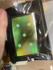
I received my Raspberry Pi 5 today, so now it’s time to build the 3rd generation of my software, trying to make it as accurate as possible using DRM/KMS + GBM + EGL + OpenGL ES, running on Pi OS Lite with no window manager. The aim is to control the display with minimal jitter and maximum reproducibility. The nice thing about these APIs is that you can actually measure when things are latched, whether you miss vblanks, etc., so you get a good idea of whether your exposure is consistent.

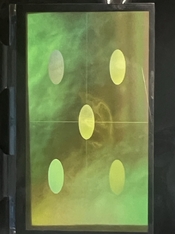
Running the panel as 1-bit and using time modulation for tonal control yields the cleanest results in my experience. Direct 8-bit exposure produced noticeable artifacts every time I tried it (most apparent in monotone areas).

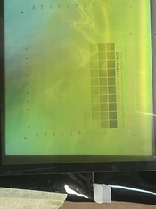
My biggest challenge right now is the highlights (toe of the paper), which need very little exposure - they build density fast. I’ll experiment with more diluted developers and other darkroom tricks, but I really want the exposure pipeline to be as accurate as possible to help with precision, especially in the highlights given they’re the trickiest for me. So I’m having fun going a bit more low-level. 🙂

One nice side effect of driving the display directly with DRM/KMS is that it basically becomes plug-and-play for timing. I don’t have to mess with modelines or force modes like others reported - the Pi just reads the EDID and I can use the panel’s preferred timing exactly as it is.

For example, I can see the mode I need straight from the EDID:

sudo cat /sys/class/drm/card1-HDMI-A-1/edid | edid-decode

Block 2, DisplayID Extension Block:
Version: 1.2
Extension Count: 0
Display Product Type: Extension Section
Video Timing Modes Type 1 - Detailed Timings Data Block:
DTD: 2840x4320 19.994380 Hz 1:1 87.175 kHz 263.270000 MHz (aspect 1:1, no 3D stereo, preferred)
Hfront 120 Hsync 20 Hback 40 Hpol N
Vfront 20 Vsync 4 Vback 16 Vpol N
Checksum: 0x16
Checksum: 0x90

And in my code I simply ask DRM for that “preferred” mode and use it:

drmModeModeInfo mode = chosen_conn->modes[0];
for (int m = 0; m < chosen_conn->count_modes; m++) {
if (chosen_conn->modes[m].type & DRM_MODE_TYPE_PREFERRED) {
mode = chosen_conn->modes[m];
break;
}
}
 

greg7mdp2

Member
Joined
Dec 22, 2025
Messages
10
Location
United States
Format
Large Format
I took a hiatus from my darkroom experiments and went down a rabbit hole designing - and having CNC machined - a carrier plate to mount the LCD in anodized black aluminum. It just arrived today, and I’m excited to get back to experimenting. Looks pretty neat!View attachment 411154View attachment 411155View attachment 411156

Wow, that's really nice. I have a Durst L1200 as well, and I also have the same display on order. Would you be willing to share your design so I can have the same carrier CNC machined as well?
 

michaelbirkmose

Member
Allowing Ads
Joined
May 4, 2014
Messages
18
Format
Medium Format
Just to add a few details: the cutout (the recessed area where the display sits) has generous tolerance. This was my first time having something CNC-machined, so I intentionally made it a few millimeters larger than strictly necessary.


The plate also includes mounting holes for a Raspberry Pi 5, which is what I’m currently using.


If it’s helpful, I can send over the STEP files and the technical drawing I provided to the manufacturer. I didn’t model the plate manually - I generated it in Python using the CadQuery library - so I can quickly produce bespoke STEP files if you’d like any changes. Of course, if you’re comfortable with CAD tools, feel free to edit it to your heart’s conten, this is all still pretty new to me, so I’m just sharing how I approached it.
 

michaelbirkmose

Member
Allowing Ads
Joined
May 4, 2014
Messages
18
Format
Medium Format
I ended up building a ultra precise rasberry pi5 solution so that I can control latching of time modulated 1bit frames with microsecond precision (from the O/S perspective, the display is running at 20hz, so you are bound by 50ms frame times). I build a bespoke UI that I control projected on the baseboard in the darkroom, using a Nintento switch bluetooth controller :D Had a lot of fun building this thing. Last step is to figure out how to generate some good LUTs.


f2daed26-bddf-47cd-b47a-b71a880c30d4.jpeg
8ed46a7b-e024-4f7f-aea4-1ca2d54ac598.jpeg


0a1cbeba-686b-4a0e-ab7c-9877e26944e2.jpeg
 

greg7mdp2

Member
Joined
Dec 22, 2025
Messages
10
Location
United States
Format
Large Format
Just to add a few details: the cutout (the recessed area where the display sits) has generous tolerance. This was my first time having something CNC-machined, so I intentionally made it a few millimeters larger than strictly necessary.


The plate also includes mounting holes for a Raspberry Pi 5, which is what I’m currently using.


If it’s helpful, I can send over the STEP files and the technical drawing I provided to the manufacturer. I didn’t model the plate manually - I generated it in Python using the CadQuery library - so I can quickly produce bespoke STEP files if you’d like any changes. Of course, if you’re comfortable with CAD tools, feel free to edit it to your heart’s conten, this is all still pretty new to me, so I’m just sharing how I approached it.

Thanks you so much, I would love the STEP files and the drawing. I am not familiar with CAD tools, so I would probably reuse your design exactly. Also if you could tell me which manufacturer you used I'll use the same.
 

greg7mdp2

Member
Joined
Dec 22, 2025
Messages
10
Location
United States
Format
Large Format
I ended up building a ultra precise rasberry pi5 solution so that I can control latching of time modulated 1bit frames with microsecond precision (from the O/S perspective, the display is running at 20hz, so you are bound by 50ms frame times). I build a bespoke UI that I control projected on the baseboard in the darkroom, using a Nintento switch bluetooth controller :D Had a lot of fun building this thing. Last step is to figure out how to generate some good LUTs.


View attachment 414188View attachment 414189


View attachment 414187

Very cool. I understand why you mounted the raspberry pi to the carrier, since you don't need an auxilliary display or keyboard. Instead of the switch controller, maybe you could have used a bluetooth mouse?
 

greg7mdp2

Member
Joined
Dec 22, 2025
Messages
10
Location
United States
Format
Large Format
I ended up building a ultra precise rasberry pi5 solution so that I can control latching of time modulated 1bit frames with microsecond precision (from the O/S perspective, the display is running at 20hz, so you are bound by 50ms frame times). I build a bespoke UI that I control projected on the baseboard in the darkroom, using a Nintento switch bluetooth controller :D Had a lot of fun building this thing. Last step is to figure out how to generate some good LUTs.


View attachment 414188View attachment 414189


View attachment 414187

If you want to share the software, that would be very cool too!
 

greg7mdp2

Member
Joined
Dec 22, 2025
Messages
10
Location
United States
Format
Large Format
my email is **** at gmail
Moderator's note: we have deleted most of the posted email, after noting that communication has been established.
While some steps had been taken to make the posted email less of an attraction to scrapers, it remains our advice that sharing an email address - or any other personal information - may not be wise if the post is public.
The scammers are out there!
It is always more prudent to share such information in a more private Conversation, either by initiating one yourself when you have attained the required privileges, or requesting that your correspondent start a private Conversation with you.
 
Last edited by a moderator:

michaelbirkmose

Member
Allowing Ads
Joined
May 4, 2014
Messages
18
Format
Medium Format
Shared the mount files by email 🙂

Regarding the controller: I just programmed the UI to match the layout of the gamepad, so there’s nothing to set up - you simply press the corresponding button. It makes things much smoother for me in the darkroom.

As for sharing the software, that one has a lot of moving parts, so it’s not something I’m planning to release. That said, I’m happy to provide pointers if you’re looking to build your own 🙂 It also looks like quite a few people in this thread have built their own solutions, and I don’t think there’s really a one-size-fits-all approach here.

The biggest takeaway for me was that 1-bit time modulation is a must (at least with my display). Without it, I was getting visible artifacts in areas with smooth tonality.
 

greg7mdp2

Member
Joined
Dec 22, 2025
Messages
10
Location
United States
Format
Large Format
Shared the mount files by email 🙂

Regarding the controller: I just programmed the UI to match the layout of the gamepad, so there’s nothing to set up - you simply press the corresponding button. It makes things much smoother for me in the darkroom.

As for sharing the software, that one has a lot of moving parts, so it’s not something I’m planning to release. That said, I’m happy to provide pointers if you’re looking to build your own 🙂 It also looks like quite a few people in this thread have built their own solutions, and I don’t think there’s really a one-size-fits-all approach here.

The biggest takeaway for me was that 1-bit time modulation is a must (at least with my display). Without it, I was getting visible artifacts in areas with smooth tonality.

Cool, thanks again. Using a game controller does make sense for using in the dark. I probably will have more questions once I receive the LCD panel and can start playing with the software.
Just curious, what language did you use for the software?
 

michaelbirkmose

Member
Allowing Ads
Joined
May 4, 2014
Messages
18
Format
Medium Format
I use Rust for the software - most of the logic is written in Rust, some of it is wrappers around the more low level Linux DRM/KMS/GBM/EGL. My approach was to build this as an appliance and take direct control of the GPU to have very precise control of latching of frames (due to the time modulation trick). My observation is with 1bit mode every frame counts when rendering the highlights (as they build up very fast).

My initial experiments was Python, then I wrote a C version, and finally a Rust version.
 

greg7mdp2

Member
Joined
Dec 22, 2025
Messages
10
Location
United States
Format
Large Format
I use Rust for the software - most of the logic is written in Rust, some of it is wrappers around the more low level Linux DRM/KMS/GBM/EGL. My approach was to build this as an appliance and take direct control of the GPU to have very precise control of latching of frames (due to the time modulation trick). My observation is with 1bit mode every frame counts when rendering the highlights (as they build up very fast).

My initial experiments was Python, then I wrote a C version, and finally a Rust version.


🙏
 

BenjaminAustin

Member
Allowing Ads
Joined
Oct 5, 2010
Messages
25
Format
Multi Format
Hi All

The supplier I was talking to recently updated their 16K screen from 3 bits per pixel to 8 bits per pixel.

Naturally - I got excited and bought one.
I tried running it on an SBC based on the rockchip - a Radxa Rock 5C (similar to the Pi 5) - but ran into a hardware limit because of the unusual dimension of the screen when taking into account the packed-pixels. (3x 8bit mono pixels per 24bit RGB pixel)

I connected to a beefier PC and dedicated NVidia card and managed to get it working. See attached.

The version of the screen I bought also had a special yellow 'UV Coating' that the supplier claims to increase UV transmissivity by 5% - but requires cross polarising to be visible to the naked eye while testing (hence the unusual colouration in the photo) - and is not suitable for visible light processes. I will buy an additional LCD with the normal coatings if I want to make traditional silver prints.

My research is pointing me towards a 'lattepanda' SBC - it has a video card that the LLMs assure me will be able to cope with the unusual dimensions - and has the benefit of a whole lot of GPIO pins for running the PWM for the UV light source, thermocouple input, other controls etc...

An interesting factor is the non-square pixels in the LCD which requires careful management to ensure the image is compensated correctly.

I've managed to get it all running using shell scripts, a little python and ImageMagick - which is super convenient.
I've even put a little web app in front of it so I can upload images and control everything remotely.
I have set up the software to handle LUTs output from QCDN for when I get to printing. This should make linearisation pretty straight forward.

The attached images show:
1. Uncompensated image showing how the non-square pixels naturally want to warp the image
2. A compensated image that takes into account the 0.756:1 ratio of the pixels.
3. A greyscale output at gamma 2.2 - I have no idea how this translates when operating on UV light yet, as my enlarger is not ready.


Happy to answer any questions :smile:

B
 

Attachments

  • IMG_2268 Large.jpeg
    IMG_2268 Large.jpeg
    147.8 KB · Views: 56
  • IMG_2269 Large.jpeg
    IMG_2269 Large.jpeg
    203 KB · Views: 53
  • IMG_2270 Large.jpeg
    IMG_2270 Large.jpeg
    155.2 KB · Views: 56

greg7mdp2

Member
Joined
Dec 22, 2025
Messages
10
Location
United States
Format
Large Format
That's very cool. I'm not quite getting how the additional coating could *increase* the UV transmissivity, I was assuming that the UV not transmitted was absorbed by the LCD material, and why would an additional coating change that? I'm probably missing something.

Also, I'm not quite understanding the benefit of having multiple grey levels. Can't you just simulate it exactly by updating the projected image as the exposure progresses, turning of pixels. You'd need just to update the image 8 times during the exposure to simulate 256 grey levels.
 

BenjaminAustin

Member
Allowing Ads
Joined
Oct 5, 2010
Messages
25
Format
Multi Format
That's very cool. I'm not quite getting how the additional coating could *increase* the UV transmissivity, I was assuming that the UV not transmitted was absorbed by the LCD material, and why would an additional coating change that? I'm probably missing something.

Also, I'm not quite understanding the benefit of having multiple grey levels. Can't you just simulate it exactly by updating the projected image as the exposure progresses, turning of pixels. You'd need just to update the image 8 times during the exposure to simulate 256 grey levels.

I think they use a different material than the standard intrinsic polarisers in a normal LCD screen - and this different material results in lowered absorption of UV. So, ultimately, your instincts are correct.

My hope is that the 256 levels of grey that the screen can display (block) will be sufficient to give me a workable greyscale without having to resort to the complexities of updating the screen within a single exposure.
I am mostly interested in gum and gum adjacent print processes (SBQ, PMF) - and these have a tiny dynamic range that is extended by application of multiple layers.

I note that the 16K screen only has a 10Hz refresh rate.
 

greg7mdp2

Member
Joined
Dec 22, 2025
Messages
10
Location
United States
Format
Large Format
I think they use a different material than the standard intrinsic polarisers in a normal LCD screen - and this different material results in lowered absorption of UV. So, ultimately, your instincts are correct.

My hope is that the 256 levels of grey that the screen can display (block) will be sufficient to give me a workable greyscale without having to resort to the complexities of updating the screen within a single exposure.
I am mostly interested in gum and gum adjacent print processes (SBQ, PMF) - and these have a tiny dynamic range that is extended by application of multiple layers.

I note that the 16K screen only has a 10Hz refresh rate.

Ah, thank you Benjamin, this makes sense. A better transmittance would be useful indeed to lower the exposure time. In the LCD I ordered (the 9k, 6.9") the transmittance is listed as only 3.5%.
I'm just starting with this process and it is a lot of fun!
 

michaelbirkmose

Member
Allowing Ads
Joined
May 4, 2014
Messages
18
Format
Medium Format
Interesting @BenjaminAustin!
Do they sell the screen both with and without the special coating? (I am purely interested in silver gelatin, so personally I hope that the industry doesn't decide to start only produce screens with this special coating :D)
 
Last edited:

AndrewBurns

Member
Joined
Jul 12, 2019
Messages
316
Location
Auckland, New Zealand
Format
Multi Format
Also a word of warning to you all- don't leave your display on when you aren't using it. I left mine on overnight and the next day had issues with image persistence (the desktop pattern staying on the screen even when I wrote other images to it). A few hours with an alternating white/black screen gif and it went away, but it was annoying.

FYI I've been seeing this effect on the LCD I use in my UV enlarger, however I'm getting persistence of the images I'm actually printing.

Because it's a UV enlarger my exposure times are typically quite long (I've made many 45 minute exposures for cyanotype prints over the last year or so) but strangely I've never seen artifacts from persistent images showing up on my photo prints.

Where I have been seeing it show up are when I do exposure tests. For example last night I did an exposure test that involved sequentially displaying 10 test patterns along the length of the screen over the course of 30 minutes. And tonight I tried to print a single test pattern for 21 minutes, and in the final print there's a clear ghost image of the exposure test I did last night. Keep in mind the test pattern gets wiped back to the desktop image after the exposure time, so the pattern from last night that left a ghost image on the screen today was only displayed for a maximum of 30 minutes.

I'm not sure why I would see the ghost image effect only after exposure tests and not prints, but I suspect it might have something to do with making the screen display entirely black or entirely white in areas? In most photos none of the pixels I display are 100% black or 100% white, there are some that are very close to those values but typically they're a little either side of fully white or black. The exposure patterns on the other hand have large areas and features that are 100% black or white, which I figure might result in more persistence than a normal photo print.

In any case, I'm currently endlessly cycling the screen between black and white like Ethan did, and hopefully after a few hours the 'burned in' images will be gone.
 

Yezishu

Member
Allowing Ads
Joined
Dec 21, 2024
Messages
205
Location
Hong Kong
Format
35mm
You'd need just to update the image 8 times during the exposure to simulate 256 grey levels.

This is a expend process. originally 256 gray levels (8 bits), added with 8 exposures will result in 16 bits (65536 gray levels). Therefore, the higher the original gray level, the better.
If the switching speed is fast enough (e.g., 16 switching times per ms), 65536 gray levels can be obtained from even black and white binary values (1 bit). This is how DMD and laser scanning works on gray levels.
 
Joined
Nov 20, 2020
Messages
106
Location
Western Massachusetts
Format
8x10 Format
FYI I've been seeing this effect on the LCD I use in my UV enlarger, however I'm getting persistence of the images I'm actually printing.

Because it's a UV enlarger my exposure times are typically quite long (I've made many 45 minute exposures for cyanotype prints over the last year or so) but strangely I've never seen artifacts from persistent images showing up on my photo prints.

Where I have been seeing it show up are when I do exposure tests. For example last night I did an exposure test that involved sequentially displaying 10 test patterns along the length of the screen over the course of 30 minutes. And tonight I tried to print a single test pattern for 21 minutes, and in the final print there's a clear ghost image of the exposure test I did last night. Keep in mind the test pattern gets wiped back to the desktop image after the exposure time, so the pattern from last night that left a ghost image on the screen today was only displayed for a maximum of 30 minutes.

I'm not sure why I would see the ghost image effect only after exposure tests and not prints, but I suspect it might have something to do with making the screen display entirely black or entirely white in areas? In most photos none of the pixels I display are 100% black or 100% white, there are some that are very close to those values but typically they're a little either side of fully white or black. The exposure patterns on the other hand have large areas and features that are 100% black or white, which I figure might result in more persistence than a normal photo print.

In any case, I'm currently endlessly cycling the screen between black and white like Ethan did, and hopefully after a few hours the 'burned in' images will be gone.

My screen is working fine now, so eventually yours should go back to working. When mine got burned in, I think I had it running for 12 hours or so unattended, and I think it took a couple days to get the effect to dissapear.
 
Joined
Nov 20, 2020
Messages
106
Location
Western Massachusetts
Format
8x10 Format
I think they use a different material than the standard intrinsic polarisers in a normal LCD screen - and this different material results in lowered absorption of UV. So, ultimately, your instincts are correct.

My hope is that the 256 levels of grey that the screen can display (block) will be sufficient to give me a workable greyscale without having to resort to the complexities of updating the screen within a single exposure.
I am mostly interested in gum and gum adjacent print processes (SBQ, PMF) - and these have a tiny dynamic range that is extended by application of multiple layers.

I note that the 16K screen only has a 10Hz refresh rate.

That's odd, the 16k screen I'm using is 20hz.

I've been reading more about these screens, and the 16k screen is more than capable of showing 8-bit images. It's the display driver board which limits it to 3-bit because 8-bit would require more processing power than the cheap driver boards have. There's currently a 3d printer manufacturer working on making an 8-bit driver board for the 16k screens, but they aren't finished yet. Whenever they finish prototyping I plan on seeing if I can get my hands on one.

Here's the link to that announcement:
https://www.concepts3d.ca/blogs/news/athena-ii-pro-announcement

That's very cool. I'm not quite getting how the additional coating could *increase* the UV transmissivity, I was assuming that the UV not transmitted was absorbed by the LCD material, and why would an additional coating change that? I'm probably missing something.

Also, I'm not quite understanding the benefit of having multiple grey levels. Can't you just simulate it exactly by updating the projected image as the exposure progresses, turning of pixels. You'd need just to update the image 8 times during the exposure to simulate 256 grey levels.

And another note- you don't need to update the image 8 times to get 8-bit (256 gray levels), you only need to update it twice during the exposure (so three images). Think about how brightness values are stored in binary, an 8-bit pixel will have 8 characters (each representing 1 bit). For this explanation I'll use the value 142 (In a 0-255 scale, I just randomly chose this by sampling a photoshop file). The binary value for 142 is 10001110, to achieve that value using a 3-bit display, add a 9th bit at the end (0) and break the 9 bit values into 3 bit chunks. Now our value is [100][011][100]. We can weight each of these chunks based on the percentage of the total value they represent. In binary each subsequent bit carries 1/2 the weight of the bit which preceded it, so each 3-bit chunk carries 1/8 (1/(2^3)) of the weight of the previous chunk. With three chunks that means for however long you display the 3rd chunk, the 2nd should be displayed for 8 times that, and for however long the 2nd is displayed, the first should be displayed for 8 times that. To calculate the exposure time for each chunk, divide your exposure time into 73 steps. Display the first binary chunk for 64/73rds of the exposure, display the second chunk for 8/73rds of the exposure, and display the third chunk for 1/73rd of the exposure.

In my system rather than adding an extra bit to an 8-bit value, I truncate 1 bit off of the 16-bit value and use the same sort of algorithm to divide my exposure into 5 frames giving me a 15-bit exposure. After I designed it I realized that I'd get the same results with a 12-bit exposure for all my silver prints, because the last 3 bits only get shown for 1 1/20th of a second frame every half hour, and most digital capture systems have a noise floor less than 15 bits.
 

Yezishu

Member
Allowing Ads
Joined
Dec 21, 2024
Messages
205
Location
Hong Kong
Format
35mm
This algorithm is limited by the physical refresh rate. Taking the aforementioned 16K 10Hz display as an example, assuming a pure white image is displayed, we cannot achieve 10 time slices of 1/2, 1/4, 1/8, 1/16, 1/32...1/1024 seconds within 1 second to obtain 2 power 10 of 10,24 grayscale levels in 10 exposures.

The physical shortest time is 1/10 second, so the practically usable time slices are 4/10 second, 2/10 second, and 1/10 second. Adding a 3/10 second margin, 4 exposures can obtain 10 grayscale levels, slightly more than 2 power 3 (8) and less than 2 power 4 (16).

Adding the display's own 3-bit (8 levels) grayscale, a maximum of 80 grayscale levels can be obtained from 4 images within 1 second.
 
Photrio.com contains affiliate links to products. We may receive a commission for purchases made through these links.
To read our full affiliate disclosure statement please click Here.

PHOTRIO PARTNERS EQUALLY FUNDING OUR COMMUNITY:


Ilford ADOX Freestyle Photographic Stearman Press Weldon Color Lab Blue Moon Camera & Machine
Top Bottom