What is the Relationship between Film Speed and Camera Exposure?

Brentwood Kebab!

A
Brentwood Kebab!

  • 1
  • 1
  • 71
Summer Lady

A
Summer Lady

  • 2
  • 1
  • 99
DINO Acting Up !

A
DINO Acting Up !

  • 2
  • 0
  • 56
What Have They Seen?

A
What Have They Seen?

  • 0
  • 0
  • 71
Lady With Attitude !

A
Lady With Attitude !

  • 0
  • 0
  • 60

Forum statistics

Threads
198,777
Messages
2,780,713
Members
99,703
Latest member
heartlesstwyla
Recent bookmarks
1
OP
OP
Stephen Benskin
Joined
Jan 7, 2005
Messages
2,612
Location
Los Angeles
Format
4x5 Format
According to the exposure meter's calibration equation, the mean scene Luminance is 297 cd/ft^2 or 3196 cd/m^2. Whatever the meter points at, the f/stop and shutter speed half of the equation wants to adjust itself to balance the equation to equal the same output as with the 297 cd/ft^2 at the Sunny 16 rule - f/16 and the shutter speed as the reciprocal of the film speed - 1/film speed.

If you remove the shutter speed out of the picture, the exposure meter wants to produce a single value that, according to Connelly, "can be considered either the average image illumination required for light sensitive material having unity film speed when exposed for a time of one second, or a constant reference exposure (P)." This value is what makes exposure meters work for all materials. It wants to produce a single exposure value.

It is the film speed of the photographic material determines where the average point of exposure or the metered exposure point will fall. As we've seen, it's not just a value representing the sensitivity of the photographic material, but also includes information about the limits of useful exposure of the film type, and most importantly an adjustment by the speed constant to place the metered exposure point at the point on the film's characteristic curve so that the entire scene's exposure range will fall on the curve where it will be most advantageous.

Now that we know the average Luminance or Lg, we can determine the constant P and then calculate the exposure value for all the different film speeds.
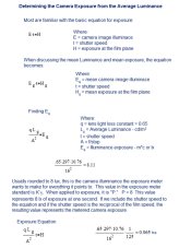
Constant P and the Metered Exposure value.jpg

There's a short cut to determine the metered exposure value for different film speeds. Simply divided the film speed into the constant P.

P/100 = 0.080
P/125 = 0.064
P/200 = 0.040
P/400 = 0.020

Now that we know the positions of both the speed point and the meter exposure point, it's now possible to determine the relationship between the speed point, film speed, and the metered exposure point.
 

Bill Burk

Subscriber
Joined
Feb 9, 2010
Messages
9,301
Format
4x5 Format
For black and white negative film, it is the point where the minimum gradient is .3x the average gradient of the film curve. By adhering to the contrast parameters of the black and white film standard, this point will always fall 0.29 log-H units to the left of the speed point (attachment - B W film speed standard and Fractional Gradient point.jpg).

I can't get my head around this. All black and white negative film has a similar shaped toe under the 0.1 speed point when developed to ASA gradient? What of long-toed and short-toed films? And if you use the 0.3x average gradient for a speed point... do you select a value for mcs that falls 0.29 to the right of the 0.3x point?
 
OP
OP
Stephen Benskin
Joined
Jan 7, 2005
Messages
2,612
Location
Los Angeles
Format
4x5 Format
I can't get my head around this. All black and white negative film has a similar shaped toe under the 0.1 speed point when developed to ASA gradient? What of long-toed and short-toed films?

Bill,
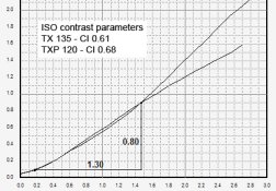
Excellent question. It all has to do with the ISO contrast parameters. The log-H range of 1.30 is designed to measure the lower portion of the film curve. Long toed curves with their slow upsweep require a higher CI to fit the the ISO conditions than a short toed film. When people refer to the ISO contrast parameters producing an gamma, contrast index, or even an average gradient of 0.61 because of the .80 / 1.30 = 0.615, they are in error as those measurement methods include a greater portion of the film curve. While this usually won't make much of a difference with the primarily straight lined short toed curves, it will with the longer toed curves.

ISO Contrast TX and TXP.jpg

And if you use the 0.3x average gradient for a speed point... do you select a value for mcs that falls 0.29 to the right of the 0.3x point?

If you are using the fractional gradient method, then yes. But it's not as simple as that. The two primary changes in the 1960 standard were the elimination of most of a safety factor and to simplify the determination of the speed point. For simplicity sake, let's just say the fractional gradient speed point falls 1 stop below where today's ISO speed point falls, and let's use the Hm value for a 125 speed film - 0.0064. This would make the .3G speed point exposure value 0.0032. If you calculate the speed using the ISO equation, the resulting film speed would be .8/.0032 = 250, but that's not the .3G speed equation. It was (1/Es) / 4 or for our example (1/.0032) / 4 = 78. So even though the .3G speed point falls ~1 stop to the left of the ISO speed point, the speeds created were ~ 1 stop slower.

For the 1960 standard, they simply could have changed the speed constant to 0.4 and divided the .3G exposure value into it: .4 / 0.0032 = 125. The reason why they didn't was because the .3G speed point was difficult to find. That's one of the reasons why they went with a density of 0.10 over Fb+f. It's exactly 1/3 stop over the film base. It's easy to determine. But the only reason why they could accept this simplified speed point was that under certain contrast conditions, the 0.10 speed point falls at a uniform distance from the .3G speed point. So, if the film is processed to those conditions, and the 0.10 speed point is used to determine the film speed, it will produce the same film speed as from the fractional gradient method. In other words, if you are adhering to the ISO contrast parameters, you are essentially using the fractional gradient method.

The implication of this is that any use of the 0.10 speed point with the film processed outside the ISO contrast parameters will no longer relate to the .3G speed point and no longer have the same correlation to the psychophysical pictorial speed tests and therefore be less accurate.

Delta-X Criterion is a method that uses a mathematical adjustment which allows the use of 0.10 as the speed point for any processing condition while still retaining the accuracy of the fractional gradient speeds.

I hope this explanation also helps clarify how the speed constant works and how the speed point isn't necessarily associated with the placement of the camera exposure. It's for testing purposes to determine the placement of the exposure.
 
Last edited by a moderator:

Bill Burk

Subscriber
Joined
Feb 9, 2010
Messages
9,301
Format
4x5 Format
So ... the .3G speed point falls ~1 stop to the left of the ISO speed point...

... under certain contrast conditions, the 0.10 speed point fell at a uniform distance from the .3G speed point...

Great, that makes sense.

The .3G and .1 speed points correlate to each other... by being a certain distance apart.
 
OP
OP
Stephen Benskin
Joined
Jan 7, 2005
Messages
2,612
Location
Los Angeles
Format
4x5 Format
The .3G and .1 speed points correlate to each other... by being a certain distance apart.

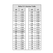
Yes, but I would like to emphasize the 0.29 only applies when the ISO contrast parameters are met, otherwise the relationship is different. Although it's not random. You can determine the Delta X value by the Delta D value while maintaining the 1.30 log-H range.

Delta X Criterion Table.jpg
 
Last edited by a moderator:
OP
OP
Stephen Benskin
Joined
Jan 7, 2005
Messages
2,612
Location
Los Angeles
Format
4x5 Format
Here are a couple of excerpts from Jack Holm's paper, Exposure-Speed Relations and Tone Reproduction, IS&Ts 47th Annual Conference, 1994. I believe it sums up what has been covered so far and begins to put into perspective the relationship between film speed and mean exposure.

“The speed values obtained from these exposure values should place the exposure values so that the corresponding tones of the scene are optimally reproduced.”

“Film speed exposure determination standards are based on the correlation of two experimental values, the film speed and the average scene luminance. These standards describe a speed point exposure which is deemed to produce a density or densities of significance for a particular film type. The optimal ratio between this exposure is then determined and used in the calculation of a constant for the speed equation. Film speeds are obtained for specific films by determining the speed point exposure and plugging the value into the speed equation to get the film speed. Since this film speed was determined assuming a particular speed-point-exposure/mean-exposure ratio, if this ratio is approximately correct, setting the film speed value on an exposure meter and reading the scene should indicate the correct exposure. The trick is to select a speed point which allows for the maximum variation in the actual speed-point-exposure /mean-exposure ratio with the minimum variation in image quality."

“It is important to note, however, that mononumeric speed values provide information about the predicted output at only one point on the characteristic curve. If a speed value is based on a shadow density, it will predict only the exposure required to produce that density, and similarly for highlight and other speed point exposure criteria. Also, typical light meters can only read one luminance value for a scene and thereby predict only one film plane exposure. The actual tone reproduction is therefore dependent on: the speed point exposure, the desired reproduction of the speed point exposure, the metered exposure, the desired reproduction of the metered exposure, and the difference between the speed point and metered exposures.”
 
Last edited by a moderator:
OP
OP
Stephen Benskin
Joined
Jan 7, 2005
Messages
2,612
Location
Los Angeles
Format
4x5 Format
So, what is this important ratio between the speed point, film speed, and metered exposure all about? This ratio is what defines the relationship between the speed point and the metered exposure point. or more specifically, the film speed and the exposure placement.
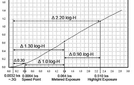
The idea is to find the optimum placement for an average scene because of it’s high occurrence, while at the same time considering maintaining the highest level of quality with variance in exposure and scene luminance range. In order to determine this placement, four variables need to be known: the film’s speed point, the metered exposure point, the average scene luminance range, and the ratio between the speed point exposure and the metered exposure.

The first three variables have already been discussed. The ratio is easy to determine. It’s Hg / Hm = k1. With the current B&W speed standard for a 125 speed film that would be:

0.064 / 0.0064 = 10 or a log 1.0

For color reversal it would be:

0.064 / 0.08 = 0.8 or a log - 0.1

What this means is the B&W ISO speed point is 1.0 log-H units to the left of metered exposure, and the color reversal ISO speed point is 0.10 log-H units to the right of the metered exposure.

Speed Point - Metered Exposure Ratio.jpg

Why is the ratio significant? If the distribution of the luminance range above and below the metered exposure point is known, optimum exposure placement can be determined by adjusting the ratio value. Changing the ratio between Hm and Hg is possible simply by changing the speed constant.
 
OP
OP
Stephen Benskin
Joined
Jan 7, 2005
Messages
2,612
Location
Los Angeles
Format
4x5 Format
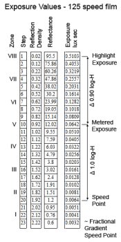
Now that we have determined the ratio between the speed point and the metered exposure, we can illustrate how an average 2.20 log scene luminance range falls onto the film curve.

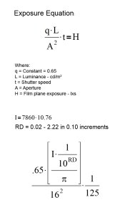
I’ve generated the exposure values using the camera exposure equation in order to confirm all the exposure values for the luminance range.

Exposure Equation for Film Speed - Metered Exposure Ratio.jpg

To help simplify things a little, I’ve made a small adjustment to the ranges above and below the metered exposure. Instead of a range of 0.92 log-H above and 1.28 log-H below, I’ve made them 0.90 above and 1.30 below. The illuminance comes from the incident exposure meter’s value for I = 7680 footcandles. It is then converted to nits (cd/m^2). The exposure is for a 125 speed film which is reflected in the shutter speed of 1/125.

Exposure for 125 speed film.jpg

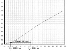
I believe this example confirms some of the concepts so far discussed. The metered exposure falls at an equivalent 12% Reflectance (RD 0.92) (step 10). We know this because for a 125 speed film, the metered exposure will be 8/125 = 0.064 lxs. The speed point exposure for a 125 speed film is 0.8 / 125 = 0.0064 and that falls at a point 1.0 log-H units below the metered exposure (step 20). This confirms the 10x ratio discussed in the last post. The shadow exposure at 0.0032 lxs falls on step 23.

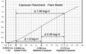
The following graph shows how the exposure placement will fall on the film’s characteristic curve.

Speed Point - Metered Exposure Ratio - Luminance Range 1.jpg
 
Last edited by a moderator:

Bill Burk

Subscriber
Joined
Feb 9, 2010
Messages
9,301
Format
4x5 Format
Well, I place my shadows on Zone II which is one third-stop above the speed point in your illustrations. And it is interesting that there "is" image information (that we don't expect to be able to print) all the way down to the 0.3G point (which is pretty close to Zone I).
 
OP
OP
Stephen Benskin
Joined
Jan 7, 2005
Messages
2,612
Location
Los Angeles
Format
4x5 Format
Take another look at it. Zone I falls at 1.20 log-H units below the metered exposure, but that's 0.20 log-H units below the speed point which also happens to be at 0.10 over Fb+f. The two don't seem to match up. What affect do you think this has on comparable film speed values?
 
Last edited by a moderator:
OP
OP
Stephen Benskin
Joined
Jan 7, 2005
Messages
2,612
Location
Los Angeles
Format
4x5 Format
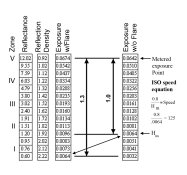
The purpose of the speed point – metered exposure ratio is to link the sensitometric exposure of the film speed testing with the camera exposure. As film speed is derived from a sensitometric exposure, it is determined from non-flare testing conditions. As a certain amount of flare exists in shooting conditions, adding a flare value to the camera exposure equation will produce more realistic film plane exposure values.

Veiling flare has the greatest influence on the deep shadows and it’s influence progressively tappers off as the exposure increase. Because of this, I’m going to focus on the exposure below the metered exposure. The example here has a flare value of one stop. The flare value is determined using the last shadow exposure value. A one stop flare factor doubles this value and then adds it to each of the other exposure values. This will double the shadow exposure but will only add around 2-3% to the metered exposure.

Exposure - 12% to shadow -  flare, no flare.jpg

Flare has effectively taken the scene’s luminance range of 2.20 and reduced it to an exposure range of 1.90. This change is down almost exclusively below the metered exposure. The exposure range has gone from a scene luminance range of 1.30 to a film plane exposure range of 1.0.

It’s done this by increasing the shadow exposure by one stop, which moves it to the right on the film curve. In the case of a one stop flare factor, it brings the exposure up to the speed point. In this situation, the metered exposure falls at a 10x ratio to the shadow exposure.

Flare isn’t consistent from scene to scene. It varies depending on a number of factors including luminance range and the distribution of the luminance values within that range. And flare is virtually impossible to measure in the field. It’s a variable that can’t be controlled. Let me repeat the Jack Holm quote from post #31, ‘The trick is to select a speed point which allows for the maximum variation in the actual speed-point-exposure /mean-exposure ratio with the minimum variation in image quality.”

This is a question of exposure placement and variance. Keep in mind that the film speed – meter exposure ratio is not intrinsic, nor is it arbitrary. It was chosen for a reason. With a flare factor of 2 (one stop) representing average flare, the shadow exposure for an average scene falls approximately one stop above the fractional gradient point. This point is the minimum point of exposure that can still insure a quality print. Even in a non-flare shooting situation, which is impossible, the shadow exposure will still fall at a usable point. This potential “safety factor” also allows for some accidental underexposure or scenes with slightly deeper shadows than the average.

As has been frequently discussed, overexposure within a certain range, doesn’t diminish image quality.

The following example uses the same film curve as post #33 with the exposure overlay incorporating the one stop flare factor.

Speed Point - Metered Exposure Ratio - Flare Model.jpg

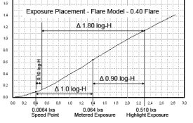
There’s a argument to be made for a slightly higher flare factor in shooting conditions, especially with smaller formats. A 1 1/3 stop flare factor moves the shadow exposure to the right an addition 0.10 log-H units.

Speed Point - Metered Exposure Ratio - Flare Model 0.jpg

What happens when the film speed constant changes, effectively changing the film speed – metered exposure ratio?
 

Bill Burk

Subscriber
Joined
Feb 9, 2010
Messages
9,301
Format
4x5 Format
Starting to hone in...

I keep confusing that while I place my shadows on Zone II, I should expect (non-flare) Zone I to be the 0.1 speed point.
 

Bill Burk

Subscriber
Joined
Feb 9, 2010
Messages
9,301
Format
4x5 Format
In another thread I had this thought...

I can't reconcile the ideas of using statistical average when I could quickly spot shadow and highlight and know the actual average.
 

markbarendt

Member
Joined
May 18, 2008
Messages
9,422
Location
Beaverton, OR
Format
Multi Format
In another thread I had this thought...

I can't reconcile the ideas of using statistical average when I could quickly spot shadow and highlight and know the actual average.

One of the joys of using an incident meter is not having to "spot" or "pick" any tone, I get the "average" automatically.
 
OP
OP
Stephen Benskin
Joined
Jan 7, 2005
Messages
2,612
Location
Los Angeles
Format
4x5 Format
It’s important to re-emphasize that the film speed – meter exposure ratio is not just chance from of the various elements involved in producing an exposure, nor is it intrinsic to the photographic process. It was chosen. Also keep in mind the film speed value isn’t intrinsic to the photographic material either. In A Review of Speed Methods, Todd and Zakia write, “The speed of a photographic material is not a fundamental concept, but provides an index number useful for calculating camera settings.” The speed point; however, does have a specific reason for it’s location. As a result, while the film speed is determined at the speed point, it might be desirable for the exposure placement to be else where.

The Fractional Gradient method is a good example of this. It’s speed point is located where the slope of the toe of the curve is equal to .3 times the average gradient of the curve. Because of this, it jumps around some, but under the current ISO standard’s parameters for film contrast, the fractional gradient (0.3G) speed point falls approximately one stop below the fixed density point of 0.10 over Fb+f.

As we’ve seen, the current ISO speed equation is 0.8/Hm. The exposure value for a 125 speed film would be .8/125 = 0.0064 lxs. If the .3G speed point falls one stop down, the exposure value there would be half of 0.0064 or 0.0032. If we apply that value to the ISO speed equation, we get .08/0.0032 = 250, but that’s not how 0.3G worked.

They wanted to give the exposure a bit of a safety factor. Meters weren’t too common, and many were bad. Many people tended to use either rule of thumb or exposure guides. So, the exposure placement needed to be elsewhere on the curve. Changing the location of the speed point was out of the question because the use of it’s location had best correlation with the psychophysical first excellent print test.

All that is required to shift the exposure placement while keeping the speed point location stable is to change the speed constant which will then change the speed point – metered exposure ratio. For 0.3G, they used 0.25 for the speed constant producing 0.25/Hm for the equation (I’m using current nomenclature to help avoid confusion). This would make the film speed for the same exposure values that resulted in a 125 speed value using the current speed stand: 0.25 / 0.0032 = 78.

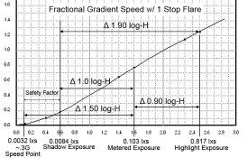
The metered exposure is then 8 / 78 = 0.103 lxs. The ratio between the speed point and the metered exposure then becomes 0.103 / 0.0032 = 32 or 1.50 log-H units. So instead of having the metered exposure fall 1.0 log-H above the speed point as with the current ISO standard. The Fractional Gradient Method had the metered exposure fall 1.50 log-H above it’s speed point. That’s a difference of 1 2/3 stops (0.50 log-H).

The below graph illustrates the exposure placement resulting from the Fractional Gradient Method. The exposure range has been adjusted to represent one stop of flare.

Factional Gradient Speed w Flare.jpg

The speed between the 0.3G speed point and where the shadow exposure falls is considered the safety factor. In addition to the shadow exposure falling 1 2/3 stops above the 0.3G speed point, it also falls 2/3 of a stop above the density of 0.10 over Fb+f. A key point to remember about speed points is that the shadow exposure doesn’t necessarily have to fall on them (for black and white negative film).

Next. How does changing the EI of the film effect the film speed – metered exposure ratio? Also, how to adjust the speed constant to create the desired change in the ratio.
 
Last edited by a moderator:
OP
OP
Stephen Benskin
Joined
Jan 7, 2005
Messages
2,612
Location
Los Angeles
Format
4x5 Format
Now let’s take a look at the changes caused by adjusting the film’s EI away from the ISO value. Most general purpose developers, when used correctly, tend to produce speeds in accordance with the ISO film speed, but it is often desirable to want a little extra exposure when shooting. So the photographer under rates the speed of the film. This might be done for a variety of reasons like for a larger safety factor, better shadow separation, or even personal taste. What does changing the EI on the exposure meter do to the film speed – metered exposure ratio?

First of all, changing the film speed setting on the exposure meter does nothing to the actual speed of the film or how the film responses to exposure. For a 125 speed film, the speed point will continue to produce a density of 0.10 over Fb+f when Hm is 0.0064 lxs no matter what the speed setting on the exposure meter. Setting a lower EI on the exposure meter will only shift the exposure placement to the right on the curve.

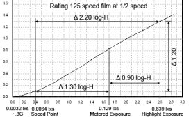
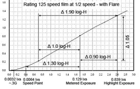
It’s common practice to under rate a film by half the ISO speed. With our 125 speed film example this would mean rating the film at 64. Because this isn’t exactly ½ of 125, I’m going to use 62.5 to keep the results simple. The metered exposure becomes 8 / 62.5 = 0.129 lxs. The ratio then becomes 0.128 / 0.0064 = 20 or a 1.30 log-H range. The two graphs below are examples of the exposure placement of the 125 speed example that has been under rated by 1 stop. One without a flare adjustment and the other with a one stop flare factor.

Speed Point - Metered Exposure Ratio - EI Change.jpg Speed Point - Metered Exposure Ratio - EI Change w flare.jpg

Just like with the Fractional Gradient Method, it’s possible to adjust the speed point – metered exposure ratio when doing the film test. Let’s say the photographer likes the results of under rating the film by one stop. Of course, he could always just half the tested film speed, or he could factor it into the sensitometric test.

It should be apparent at this point that adjusting the film speed by changing the placement of the speed point is the wrong approach. It would not only lose the connection with the exposure limits of the film curve, but it would also lose the good correlation between the sensitometric method and the psychophysical method of speed determination.

The only credible sensitometric approach is to change the speed constant from the film speed equation while keeping everything else the same. For our 125 speed film, the constant will go from 0.8 to 0.4.

0.8 / 0.0064 = 125
0.4 / 0.0064 = 62.5

We’ve shown how the ratio can be determined from dividing the speed point exposure value into the metered exposure value. It can also be determined by dividing the speed constant into the exposure constant.

8 / 0.8 = 10 or 1.0 log-H
8 / 0.4 = 20 or 1.30 log-H
From the fractional gradient method: 8 / 0.25 = 32 or 1.50 log-H.

Some of those familiar with the Zone System might be starting to wonder about the Zone System’s testing method of using a speed point – metered exposure ratio of 1.20 log-H.
 

Bill Burk

Subscriber
Joined
Feb 9, 2010
Messages
9,301
Format
4x5 Format
Interesting that your second diagram showing half film speed with flare...

Counting down stops/Zones from V.

Metered/placed Zone I falls only one-third stop to the right of the 0.1 speed point (a sane match for Zone I). And metered/placed Zone 0 falls one-third stop to the right of the 0.3G speed point (a sane match for Zone 0).

So I prefer a placement that is one-third stop to the left (faster) of the placement in your second diagram. My EI is two-third stops under rated film speed. I expect this to land my Zone I placements on 0.1 density on the film. Anything that would meter Zone 0 I would expect no density (threshold only).

It seems better to maintain the sensitometry to standard, so that it looks right in comparison to documentation. Then to shift EI at the last minute to accommodate preference/taste.

No?
 

Bill Burk

Subscriber
Joined
Feb 9, 2010
Messages
9,301
Format
4x5 Format
It seems better to maintain the sensitometry to standard, so that it looks right in comparison to documentation. Then to shift EI at the last minute to accommodate preference/taste.

Sounds like I said it ambiguously.

I mean it is easier to shift EI which affects exposure placement by changing where you place exposure. (I mean it does exactly what I want). So it seems better to shift EI
 

markbarendt

Member
Joined
May 18, 2008
Messages
9,422
Location
Beaverton, OR
Format
Multi Format
Sounds like I said it ambiguously.

I mean it is easier to shift EI which affects exposure placement by changing where you place exposure. (I mean it does exactly what I want). So it seems better to shift EI

This actually brings up something that I have wondered about for a while.

Why is it that we don't set spot meters to read the camera setting directly from the speed point?

The math isn't the issue since the formula can be adapted.
 

Chuck_P

Subscriber
Joined
Feb 2, 2004
Messages
2,369
Location
Kentucky
Format
4x5 Format
Metered/placed Zone I falls only one-third stop to the right of the 0.1 speed point (a sane match for Zone I). And metered/placed Zone 0 falls one-third stop to the right of the 0.3G speed point (a sane match for Zone 0).

Where on the horizontal axis of that graph are you claiming that Zone 0 and Zone I lies? Just curious here.....
 

markbarendt

Member
Joined
May 18, 2008
Messages
9,422
Location
Beaverton, OR
Format
Multi Format
This actually brings up something that I have wondered about for a while.

Why is it that we don't set spot meters to read the camera setting directly from the speed point?

The math isn't the issue since the formula can be adapted.

Putting some numbers to this thought for an ISO 125 film.

When metering from shadows, set meter at maybe EI 2000 (+or-).

When metering from a face, set meter at maybe EI 64.
 

Bill Burk

Subscriber
Joined
Feb 9, 2010
Messages
9,301
Format
4x5 Format
Where on the horizontal axis of that graph are you claiming that Zone 0 and Zone I lies? Just curious here.....

I'm calling the metered point Zone V and counting three-columns each per Zone
 

markbarendt

Member
Joined
May 18, 2008
Messages
9,422
Location
Beaverton, OR
Format
Multi Format
What is the point of that? It is the same as setting your EI and reading the differences in f-numbers.

If you always meter to the same point, say zone 3, to set exposure it gives a direct finished reading on the meter, no math required after taking the reading.

Measuring SBR would essentially be unchanged.
 
Photrio.com contains affiliate links to products. We may receive a commission for purchases made through these links.
To read our full affiliate disclosure statement please click Here.

PHOTRIO PARTNERS EQUALLY FUNDING OUR COMMUNITY:


Ilford ADOX Freestyle Photographic Stearman Press Weldon Color Lab Blue Moon Camera & Machine
Top Bottom