Understanding EI???

Where Did They Go?

A
Where Did They Go?

  • 2
  • 2
  • 37
Red

D
Red

  • 4
  • 3
  • 110
The Big Babinski

A
The Big Babinski

  • 2
  • 6
  • 155
Memoriam.

A
Memoriam.

  • 7
  • 8
  • 208
Self Portrait

D
Self Portrait

  • 3
  • 1
  • 104

Forum statistics

Threads
198,020
Messages
2,768,266
Members
99,529
Latest member
elgatosuizo
Recent bookmarks
0
Joined
Jan 7, 2005
Messages
2,603
Location
Los Angeles
Format
4x5 Format
Steve

Before I labor through your long note, could you please paraphrase, in a sentence or two, what you are trying to get across? I cannot get rid of the feeling that we are in violent agreement, and just prefer to expose and process our films differently. Keep in mind, nobody questions ISO. We are just trying to clarify what EI means to different people.

Jack Dunn's book is missing in my otherwise pretty extensive library, so I ordered a used copy on the web. (Actually, I accidentally ordered two, so, if somebody is interested?) Interestingly enough, it is published by the same company as mine, and I still have never heard of it. I'll never seize to learn.

Well, I find there are two different "types" of EIs. One is simply how you want to set the meter. It can be to give the film a little more exposure or to "push for speed." The other type concerns the Effective Film Speed of the film. Effective film speed is the speed derived from testing outside the method specified in the standard. You can't use the ISO prefix, but it still represents a quantitative result from some form of testing.

My contention is that in most instances, because of incorrect assumptions, the EFS type of EIs many think they are getting is really the other type. Then assuming they have an accurate result, they ascribe false attributes to the ISO standard. They now believe they have the "real" speed of the film, or that they have a personal speed that better reflects their methods. What they are really doing is working under the false sense of accuracy thinking that they have an EFS type of EI when they don't.

When I present certain facts without supporting evidence and they are rejected, I then need to explain them. There are certain fundamental concepts that have to be understood before it's possible to overturn those false assumptions. For example, you and I have talked previously about the Delta-X Criterion and I've had to present large amounts of documented information to support it. Tell you the truth, I still don't think you believe it. Even within this thread there has been rejections of the fractional gradient point as the minimal useful density point and the information presented in the exposure chart. And others aren't advanced as you.

People can explain how to do Zone System testing, but does anyone ever wonder if it is correct?

Make sure you keep the fourth edition of Exposure Manual.
 

Chuck_P

Subscriber
Joined
Feb 2, 2004
Messages
2,369
Location
Kentucky
Format
4x5 Format
Even within this thread there has been rejections of the fractional gradient point as the minimal useful density point and the information presented in the exposure chart.

Stephen,
Yes, I, for one, reject it, for now. But I do so under the advisement of "myself" :smile:
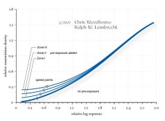
. To my understanding, the basic fractional gradient at point #1 (what is it's log exposure value by the way?) on the graph you presented basically "looks" to be a base+fog level on any other graph as far as I can tell. I can't print that on my paper with any degree of satisfaction. So, it then becomes irrelevant to me. If I can't print it, it is non-essential information.

Since we know what #4 is on the zone scale, zone I 2/3, correct? Then another 2/3 of a zone to the left would be zone I, or log exposure value 0.0. Help me with the positions on the zone scale of #1, #2, and #3? The x-axis units are confusing me. Please be brief.

People can explain how to do Zone System testing, but does anyone ever wonder if it is correct?

No.

Like I and others have tried to explain, negative density below 0.1, perhaps to .09 are valueless---this has been confirmed in practical usage. So questioning the basic concept in the ZS that a neg density of 0.1 really is the "useful threshhold" is not warranted when that assertion can be clearly verified on the surface of the print.

Chuck
 

Photo Engineer

Subscriber
Joined
Apr 19, 2005
Messages
29,018
Location
Rochester, NY
Format
Multi Format
The three part graph posted earler is quite familiar to me. I have said before that the final EI is derived from working backwards from the print. In our work, we used a 4 part graph with the final part being the print and the one part being the slope of the line with which the film is reproduced by the paper. It is called the silver criterion.

In any event, starting with the paper, one knows that the eye "sees" the world with a gamma of 1.0. Due to the laws of physics and chemistry, a toe and shoulder are imposed on all photomaterials. Therefore, the eye, integrating a print, requires a gamma of greater than 1.0 to see the print as resembling or reproducing the natural scene.

Thousands of pages of work have been published to show empirically that the curves to achieve a natural looking print fall between about 1.2 and 1.7. This is integrated via the eye using the toe, shoulder and mid scale to form a natural image. A value of 1.5 was chosen to be the optimum for "normal" contrast prints. Now, working backwards from this one can have a whole gamut of combinations of film and paper to give a value of 1.5 as the print contrast, but negative film was designed to have a long tone scale with several stops of over and under exposure allowed. It was determined at Kodak and other companies at the same time that the values of 0.6 and 2.5 for the gamma of the film and paper were optimum for this purpose.

The film was increased to 0.63 to account for flare.

As a result, working backwards and using a 4 part graph, one can place the desired exposure on the film, centering it just above the toe and on the straight line. This gives the optimum EI which can then be converted to the true EI using the X axis to derive the Log Exposure needed for a given ISO rating.

This sums up the entire process in simple language. The zone system is simple sensitometry in which an H&D curve of 21 steps is divided by 3 to give 7 steps for ease of use. It was intended so as to fit it into the straight line so that a simple ruler could be used to draw the most useful portion of the film "curve" without any "curve" being needed and without any distortion (or minimum distortion) of the original image, which was the intent. There should be no, or minimum distortion.

If you go outside of those paramaters, you distort the image in one way or another, but this is not udesirable if one wishes to achieve a certain look or character to ones images and this is what art is all about. Dodging and burning are methods of distortion of the negative image on a localized basis. Over and under exposure or development are the same on a global negative wise basis.

In any event, this is the practical and simple method of how EI or ISO is derived.

PE
 

keithwms

Member
Joined
Oct 14, 2006
Messages
6,220
Location
Charlottesvi
Format
Multi Format
As I look through the Gallery and see the the film used and the ISO rating I see that many time people shot film at rating different than the box speed.
Can some one explain the basic reasons that this technique is used? If you rate a film slower, say a 100 ISO box, shot at 80 what is the reason? Is it more tone, more contrast????

Answers will vary, of course. The only film I use that I habitually rate at a speed significantly different from box speed is xp2; it is extremely flat at box speed when metered normally. I rate it at 320 at least, sometimes slower. No doubt you will find some folks rating it at 200.

As mentioned, this rating business mostly has to do with where things fall on the three main parts of the tone curve (toe, shin, and knee). The main point, in my opinion, is where you want the contrastiest tone separation. Very broadly speaking, if you expose at box speed and meter in a neutral/average way, then the midtones will get the most separation. This is because the midtones will fall on the center of the density/exposure curve where the slope is maximum. But the thing is, we often don't really value the midtones as much as the highlights and shadows- the higher tone gradients are what makes some images appear snappier. Opinions will inevitably vary on where that high-slope part of the curve should go. Artistic decision.

In my simple version of the story, there are two roughly equivalent ways to approach this issue: by (1) rating, and (2) metering. You can quite easily translate one into the other. E.g. if you want more highlight separation then you will tend to underexpose the film.... so you could do that by rating it faster than box speed or by metering to 'protect' the highlights so that they fall on the linear part of the exposure/density curve. If you want more shadow detail then you will do the opposite, akin to rating the film slower than box speed. In either case, I think what you are really doing is devaluing the midtone separation, so to speak, and placing more value on the transitions to the highlights or shadows.

Now, this issue of tying the rating to a change in dev times is another topic altogether. My feeling is that at least for a beginner one has to standardize something and for me that was the dev time; if I had doubts about where my tones would fall, I simply bracketed and developed everything together and picked my fave. But that's not the whole story: the next step would be to consider that different developers and dev times will bring more or less range into the neg, e.g. there are compensating and supercompensating and noncompensating potions, and there are pyro potions that tend to save highlights even when you place them right on the knee, etc. Not to mention the many powerful things you can do to a developed neg like proportional or nonproportional reduction and intensification etc. Not to mention all the things you can do in the print phase, assuming that the detail you want is in the neg. (IMHO you could decide to expose and develop to weight all the tones ~equally, aim for a flat neg, and handle all this business in the print phase... kind of the complete opposite of the BTZS approach!)

I think my advice would be first and foremost to consider tone placement on the toe/shin/knee... and once comfortable with that concept go on to consider the overall compression or expansion of the tone curve... if you need to. I say "if" because modern neg films and developers are so forgiving that it's not like we're fighting some battle for shadow or highlight detail- middle of the road, standard procedures almost always yield good results.

YMMV, as everyone says....
 
Last edited by a moderator:

RalphLambrecht

Subscriber
Joined
Sep 19, 2003
Messages
14,609
Location
K,Germany
Format
Medium Format
...For example, you and I have talked previously about the Delta-X Criterion and I've had to present large amounts of documented information to support it. Tell you the truth, I still don't think you believe it...

Make sure you keep the fourth edition of Exposure Manual.

Steve

I don't question the delta-x criterion at all. It is a sound method to determine film speed. It's well published and accepted by image scientists. However, I question that the additional complexity of it is of any value to the practising photographer doing his or her own testing. Also, as others have already mentioned, theoretical discussions about density values below 0.10 are meaningless. Regardless of what theoretical image scientists will tell you, these values have no contrast to speak of and are not 'useful' to a printer trying to get some tonal information out of Zone 0. Minimum density testing works just fine with most modern emulsions.

Yes, I got the 4th edition, twice! Thanks for the reference.
 

RalphLambrecht

Subscriber
Joined
Sep 19, 2003
Messages
14,609
Location
K,Germany
Format
Medium Format
PE

I was sure, you would be familiar with the graph, and I know from previous conversations that Steve is also familiar with it.

I call it Nelson's Objective Tonal Reproduction Cycle. It is well documented in Mees' 'The Theory of the Photographic Process'. Yes, the fourth quadrant is missing. It is quite an important one, because it shows how well the the final print represents the subject. I have used it to plot the tonal cycle for the Zone System, several materials, digital negatives and hybrid printing techniques. One of my examples is attached. It is a very revealing graph. Too bad people like Nelson and Jones are no longer around.
 

Attachments

  • ReproCycle.jpg
    ReproCycle.jpg
    57.9 KB · Views: 135

Photo Engineer

Subscriber
Joined
Apr 19, 2005
Messages
29,018
Location
Rochester, NY
Format
Multi Format
Ralph, your plot is entirely correct with one omission. W. T. Hanson of EK has shown that the color of silver images is not black or gray but rather varies across the spectrum, and therefore the adjust for flare must also be adjusted for each photo film and paper to account for spectral sensitivities of them both to give accurate results.

Just as the plot without the adjust for flare is a very close approximation and the adjust for flare is even closer, the adjust for the "silver criterion" is almost exact. However, due to the adjust in contrast for flare from 0.6 to 0.63, the flare figure was omitted and only the silver criterion was used in our work.

I did many of these plots as we adjusted the spectral sensitivity of the paper and the dye set in color films. It was a very time consuming effort to do this and to balance the EI.

In the final analysis though, you and Steven are not in total agreement in that he is saying that use of point (4) in the graph is useful, but both you and I are saying that point (4) is only useful under some conditions and will lead to some loss of data in the shadow areas of the final print.

Remember that Delta density in the print is the slope of the film x the slope of the paper. If the paper in the toe is 0.3 and the film is 0.6 (toe and straight line) then the differences are in terms of the product or 0.18 per zone, but if the difference is 0.3 and 0.3 then the difference is 0.09 per zone or 50% less image discrimination and 50% loss in detail.

PE
 

Chuck_P

Subscriber
Joined
Feb 2, 2004
Messages
2,369
Location
Kentucky
Format
4x5 Format
A question for PE and or Ralph,

Stephen, I'm aware of your thoughts on this but please be brief if you respond, thanks.

If I had an older uncoated lens that introduced significant noticeable flare, thereby adding density to the negative, let's consider it unwanted density. Is that density effectively neutralized by the calibration process as is commonly done under ZS principles? Meaning, controlling the speed point at zone I and calibrating normal development at zone VIII, or IX for that matter, either way. Does this "act" of calibrating account for such a variable as lens flare? In other words, is the added density caused by the flare effectively neutralized by a negative density range that one consistently develops for? In my case, a range of 1.2 between zone I and zone VIII. In The Negative we are led to believe this, but I thought I would get your thoughts.

I believe it is probably not an issue worth being concerned about with modern day multi-coated lenses but maybe not, IDK.

Chuck
 
Joined
Jan 7, 2005
Messages
2,603
Location
Los Angeles
Format
4x5 Format
Steve

I don't question the delta-x criterion at all. It is a sound method to determine film speed. It's well published and accepted by image scientists. However, I question that the additional complexity of it is of any value to the practising photographer doing his or her own testing. Also, as others have already mentioned, theoretical discussions about density values below 0.10 are meaningless. Regardless of what theoretical image scientists will tell you, these values have no contrast to speak of and are not 'useful' to a printer trying to get some tonal information out of Zone 0. Minimum density testing works just fine with most modern emulsions.

I call it Nelson's Objective Tonal Reproduction Cycle.

Ralph,

I heard it was once called the Jones Curve.

The Delta-X Criterion might be more complex, but it is more accurate and it is part of the current ISO standard. I also think that if someone is advanced enough to plot curves, they should have a calculator to do an additional math problem. Plus the implication of the concepts involved with the process can be helpful beyond simply obtaining a film speed. Anyway, I've attached a table comparing the differences between fixed density and Delta-X speeds. Notice how at the Δ 0.80, which is the ISO standard, there is complete agreement between the two methods. Beyond that, the speed differences aren't dramatic, but it questions the affect of developmental differences on film speed. It also questions whether people really getting the film speeds and exposures they think they are getting?

I'm curious to hear what you think about the metering/speed point discrepancy with the Zone System or to put it another way, the 3 1/3 stop relationship between the meter calibration point and the speed point.

PE -I have said before that the final EI is derived from working backwards from the print.

Since the current ISO standard is based on the first excellent print test by Jones which also worked backwards, so is the ISO, and that is the biggest difference from all other speed methods before.

Steve
 
Last edited by a moderator:

RalphLambrecht

Subscriber
Joined
Sep 19, 2003
Messages
14,609
Location
K,Germany
Format
Medium Format
Ralph, your plot is entirely correct with one omission. W. T. Hanson of EK has shown that the color of silver images is not black or gray but rather varies across the spectrum, and therefore the adjust for flare must also be adjusted for each photo film and paper to account for spectral sensitivities of them both to give accurate results.

...

I did many of these plots as we adjusted the spectral sensitivity of the paper and the dye set in color films. It was a very time consuming effort to do this and to balance the EI...

PE

PE

I would love to see an example. Do you still have one?
 
Joined
Jan 7, 2005
Messages
2,603
Location
Los Angeles
Format
4x5 Format
A question for PE and or Ralph,

Stephen, I'm aware of your thoughts on this but please be brief if you respond, thanks.

If I had an older uncoated lens that introduced significant noticeable flare, thereby adding density to the negative, let's consider it unwanted density. Is that density effectively neutralized by the calibration process as is commonly done under ZS principles? Meaning, controlling the speed point at zone I and calibrating normal development at zone VIII, or IX for that matter, either way. Does this "act" of calibrating account for such a variable as lens flare? In other words, is the added density caused by the flare effectively neutralized by a negative density range that one consistently develops for? In my case, a range of 1.2 between zone I and zone VIII. In The Negative we are led to believe this, but I thought I would get your thoughts.

I believe it is probably not an issue worth being concerned about with modern day multi-coated lenses but maybe not, IDK.

Chuck

Flare is a hugh factor and it is woefully under dealt with in most literature. Modern lenses produce around 1 to 1 1/3 stops of flare for the average scene. Flare factors into film speed. Without it, film speed would be a stop slower. It factors into development. Normal development is actually development for a 6 stop range because the average 7 1/3 stop scene is reduced to 6 stops at the film plane from the affects of flare. You can see how flare changes the scene's luminance range on the film place in the camera image/flare quadrant in the reproduction curves from the long post.

80% of flare comes from the subject and is related not just to the range of luminance but distribution. A small white area surrounded with a large dark area will have less flare than a small black area surrounded by a large white area. And in both cases, the shadow density will fall at different places on the curve even though the exposure remains constant. For any given scene, flare makes it impossible to absolutely be certain what densities you will be producing.

The ISO standard incorporates a stop flare into the process. That is why the speed point is only 3 1/3 stops below the meter calibration point. It is also one of the reasons why the minimum useful density point is one stop lower than the speed point. It's a flare and underexposure safety factor. You can have zero flare and still have a usable exposure. Zone System testing uses a single toned subject which has very little flare so, IMO, it doesn't reflect real world use and doesn't give as accurate of film speeds. Interesting enough, because of playing with numbers, the ZS contrast gives you correct normal development for the stated range but not for the reasons it states.

Average flare also changes with different scene luminance ranges. It tends to increase as the Log Subject Luminance Range (LSLR) increases and visa versa. For those who do curves and use a formula to calculate target CIs, whether to use a fixed density value or variable density variable into the equation can have a big effect on the outcome.

For the most part with flare and normal scenes, you can deal with it using different paper grades.

I've attached a curve showing the affects of varying subject luminance ranges on flare. If there were no flare present, the placement would be at film base plus fog. There was no change in exposure settings. The different densities come only from flare.
 
Last edited by a moderator:

Photo Engineer

Subscriber
Joined
Apr 19, 2005
Messages
29,018
Location
Rochester, NY
Format
Multi Format
Chuck;

As flare goes up, apparent contrast goes down. However, if you compensate in development, you can "adjust" for flare in terms of its effect on contrast. You cannot fix the other problems associated with flare however, which can rather substantially degrade the image. I am not an expert in this degradation and so cannot discuss it too much, I am mostly familiar with the correction of contrast. This is a very complex issue.

Ralph;

Alas, I have none of the 4 part charts. They are the property of EK. However, I did find one hand drawn chart of the sensitivities of the two green sensitizing dyes used in color paper at the time. This was from Ektacolor 20 and Ektacolor 30 papers which contained a broad sensitizer and a narrow sensitizer respectively. The magenta imaging dyes also changed from a broad to a narrow dye respectively. This changed the 4 part curve dramatically as I had to do it for neutrals and for every possible color. That was a very painstaking chore involving hundreds of exposures.

So, all I have are the spectral sensitivities on a sheet of graph paper that I would have to scan in. Not very interesting IMHO.

PE
 

RalphLambrecht

Subscriber
Joined
Sep 19, 2003
Messages
14,609
Location
K,Germany
Format
Medium Format
...
If I had an older uncoated lens that introduced significant noticeable flare, thereby adding density to the negative, let's consider it unwanted density. Is that density effectively neutralized by the calibration process as is commonly done under ZS principles? Meaning, controlling the speed point at zone I and calibrating normal development at zone VIII, or IX for that matter, either way. Does this "act" of calibrating account for such a variable as lens flare? In other words, is the added density caused by the flare effectively neutralized by a negative density range that one consistently develops for? In my case, a range of 1.2 between zone I and zone VIII. In The Negative we are led to believe this, but I thought I would get your thoughts...

Chuck

Maybe not entirely correct (because it comes through an image forming lens), but I treat lens and camera flare just like non-image pre-exposure. In other words, if you pre-expose your film, as AA suggests to increase shadow detail (IMO only good for graded papers BTW), you get a similar effect to flare. See the attached graph.

Both change the characteristic curve of the film (mainly toe, some midtone, no highlights) and increase film speed. Steve is going to fight me on the speed-point bit, because it's of course based on fixed shadow density. Also, PE made a valid point earlier, because with large pre-exposures or flare, the toe can get sufficiently soft for gradient and fixed-density methods to deviate significantly.
 

Attachments

  • PreExposure.jpg
    PreExposure.jpg
    38.8 KB · Views: 101

RalphLambrecht

Subscriber
Joined
Sep 19, 2003
Messages
14,609
Location
K,Germany
Format
Medium Format
As flare goes up, apparent contrast goes down. However, if you compensate in development, you can "adjust" for flare in terms of its effect on contrast.

I'm not convinced. Since flare affects toe, midtones and shoulder differently, I don't see how development can correct for it. It can, of course, correct and bring back the total negative density range, but the shape of the characteristic curve is distorted by flare. I don't believe a change in development can correct that.

...So, all I have are the spectral sensitivities on a sheet of graph paper that I would have to scan in. Not very interesting IMHO...

I was more interested in seeing how this was graphically handled throughout the tonal reproduction cycle (more than four quadrants?).
 

Photo Engineer

Subscriber
Joined
Apr 19, 2005
Messages
29,018
Location
Rochester, NY
Format
Multi Format
Ralph;

I have seen flare in extremely high negative density areas as well. This is vaguely like solarization, but of course, not exactly like it. Just a hint of its appearance to me in the final result. That is the only way I can describe it. But then, extreme overexposure in some films does give solarization and it is often hard to distinguish between the two at a cursory glance. You have to closely examine the low density areas of the negative.

PE
 
Joined
Jan 7, 2005
Messages
2,603
Location
Los Angeles
Format
4x5 Format
Ralph,

My only concern is using film curves to show flare. The film curve doesn't really change and I believe some important information isn't available whereas it is using a camera image/flare curve. For instance, flare increases the placement of the shadow on the film curve, so it does automatically places it on a higher part of the curve to a degree. Please refer to my three quadrant reproduction curve for an example.

Steve
 
Last edited by a moderator:

RalphLambrecht

Subscriber
Joined
Sep 19, 2003
Messages
14,609
Location
K,Germany
Format
Medium Format
...The Delta-X Criterion might be more complex, but it is more accurate and it is part of the current ISO standard. I also think that if someone is advanced enough to plot curves, they should have a calculator to do an additional math problem...

Only if it is worth the effort. I'm not a scientist. Well, I am, but for the sake of this conversation, I'm a wannabe photographer. No extra work for no return. To satisfy a scientific curiosity, yes, by all means, but for Zone System work, no thanks.

...Notice how at the Δ 0.80, which is the ISO standard, there is complete agreement between the two methods. Beyond that, the speed differences aren't dramatic, but it questions the affect of developmental differences on film speed...

See, it is not worth it. Plus, the fixed density method gives me more exposure, which, for a Zone System advocate like me, can never hurt.

...It also questions whether people really getting the film speeds and exposures they think they are getting?...

They do, according to their definition of film speed!

...I'm curious to hear what you think about the metering/speed point discrepancy with the Zone System or to put it another way, the 3 1/3 stop relationship between the meter calibration point and the speed point...

You are correct, this is typically the case. There is a metering standard (one for incident and one for reflective measurements), but unfortunately, it is not followed by exposure meter manufacturers. I do agree, however, that the standard (and what is actually done) differs from the famous 18%. Actual lightmeter calibrations are typically to a lower value, assuming the average scene to reflect less, which means more exposure if you visualize the measurement at 18% or Zone V. To me, this makes little difference. It moves the shadow points a bit more up the curve, just where I like them!
 

RalphLambrecht

Subscriber
Joined
Sep 19, 2003
Messages
14,609
Location
K,Germany
Format
Medium Format
Ralph,

My only concern is using film curves to show flare. The film curve doesn't really change...

Steve

Have you looked at my graph in post #113? Did the characteristic curve not change with additional non-image exposure?
 
Joined
Jan 7, 2005
Messages
2,603
Location
Los Angeles
Format
4x5 Format
Steve

Have you looked at my graph in post #113? Did the characteristic curve not change with additional non-image exposure?

The curve itself actually doesn't change with flare. The exposure is simply placed upon it. The approach you are using is conceptually misleading. That's why that approach to showing the effects of exposure was mostly abandoned for the reproduction curve.

There is a metering standard but unfortunately, it is not followed by exposure meter manufacturers.

Really? Do you have any proof of that? It's another urban myth IMO. Just like Adams' K factor conspiracy theory or that meters read 18%.

See, it is not worth it. Plus, the fixed density method gives me more exposure, which, for a Zone System advocate like me, can never hurt.

Actually, fixed density gives you less.

But simply knowing that the film speed doesn't really change much with development, according to the Delta-X Criterion principles, eliminates the need to do endless testing and worrying about how speed changes with processing. When I'm shooting a scene and intend on doing extended processing, I know I don't need to change my EI. And that is worth it even if you don't go to the trouble of using the criterion.

Ralph the it's not worth it argument can be applied with someone preferring the ease of using the box speed instead of ZS testing or ZS testing instead of sensitometric testing because it is less work. It's really kind of a cop out argument.

It moves the shadow points a bit more up the curve, just where I like them!

Isn't that what I been saying all along? There's nothing wrong with the additional exposure and the results people will be getting. Just that I think people should be aware of it so they know what is really going on. And again we are having two different lines of conversation - preference vs how it works. We're not discussing the same topic.

Chuck,

I've attached a couple of developmental tables. One show the resulting CIs from different developmental models and how they deal or don't deal with flare. The other is a table from Kodak using a fixed flare model.
 
Last edited by a moderator:

Photo Engineer

Subscriber
Joined
Apr 19, 2005
Messages
29,018
Location
Rochester, NY
Format
Multi Format
I'm not convinced. Since flare affects toe, midtones and shoulder differently, I don't see how development can correct for it. It can, of course, correct and bring back the total negative density range, but the shape of the characteristic curve is distorted by flare. I don't believe a change in development can correct that.


I was more interested in seeing how this was graphically handled throughout the tonal reproduction cycle (more than four quadrants?).

Ralph;

Yes, I agree that the curve is not affected uniformly, but you can approximate the result by increasing contrast. This is why Consumer films are higher in contrast than Professional films. It is assumed that consumers cheaper cameras have higher flare. (read point and shoot plastic lenses as an example) But, this is, as you point out, a simplistic answer. (among other things, the average consumer prefers higher contrast and this is why there are professional papers and photofinisher papers for B&W and color both)

As for the graphs, four quadrants were used on 4 sheets of paper, one each for R, G, B and one for a neutral. Or, you could use 2 4 quadrant graphs, one for RGB and one for a neutral. Of course, the neutral was also constructed of RGB curves to get the exact correlation.

These were accompanied by a set of undercut images to gauge the interimage effects (IIE) on the color reproduction. I have one of those and have attached one from a series of about 100. You do them on film and measure integral and analytical density, then print them onto a print material and do the same analysis. You can then plot this on a 4 quadrant chart to examine the effects of spectral sensitivity and dye hue (and IIE) on the final image tone scale.

So, the whole thing is much more complex in color than B&W. Probably by an order of magnitude.

If you look at one of the earlier posts with graphs, there is a flare curve showing the approximation of its overall effects. Imagine that and all of the tests I have described here, done with every color and you will see that flare takes a very small position in the overall picture and is therefore just compensated for by the approximation of increased contrast.

PE
 

Attachments

  • undercut1.jpg
    undercut1.jpg
    18.8 KB · Views: 109

RalphLambrecht

Subscriber
Joined
Sep 19, 2003
Messages
14,609
Location
K,Germany
Format
Medium Format
The curve itself actually doesn't change with flare...

Steve
If you don't see that curve changing with flare, in the graph attached to post #113, I don't know what else to say, really.

...Really? Do you have any proof of that? It's another urban myth IMO. Just like Adams' K factor conspiracy theory or that meters read 18%...

Conversation with Gossen technical support, but you can read the standard yourself and check the calibration factors for Gossen, Minolta, Sekonic and Pentax meters. Most are published in the instruction manuals or on the web. You'll see. All different. No myth.

...Actually, fixed density gives you less..

Yes, less speed, more exposure.

...But simply knowing that the film speed doesn't really change much with development, according to the Delta-X Criterion principles, eliminates the need to do endless testing and worrying about how speed changes with processing. When I'm shooting a scene and intend on doing extended processing, I know I don't need to change my EI. And that is worth it even if you don't go to the trouble of using the criterion...

Steve
No, it's not. You can repeat this as often as you like. It's still wrong.
Film speed does change with development!
 

Andrew O'Neill

Moderator
Moderator
Joined
Jan 16, 2004
Messages
11,821
Location
Coquitlam,BC Canada
Format
Multi Format
To the original poster,
For many photographers, shadow seperation is important. To achieve this, one must give more exposure. For example when I use HP5+ which has an ISO of 400, I use an EI of 250 for normal situations. TMY-2 gets an EI of 320. It is important that you test to see what EI works best for you.
 

RalphLambrecht

Subscriber
Joined
Sep 19, 2003
Messages
14,609
Location
K,Germany
Format
Medium Format
Ralph;

Yes, I agree that the curve is not affected uniformly, but you can approximate the result by increasing contrast. This is why Consumer films are higher in contrast than Professional films. It is assumed that consumers cheaper cameras have higher flare. (read point and shoot plastic lenses as an example) But, this is, as you point out, a simplistic answer. (among other things, the average consumer prefers higher contrast and this is why there are professional papers and photofinisher papers for B&W and color both)...

Interesting! Makes sense.
 
Joined
Jan 7, 2005
Messages
2,603
Location
Los Angeles
Format
4x5 Format
Steve
If you don't see that curve changing with flare, in the graph attached to post #113, I don't know what else to say, really.

Ralph, I understand the concept, and based on our conversations, I think you know I have a pretty good grasp of the concept of flare and sensitometry. I'm talking about the form of the presentation of information. I'm not saying there isn't a change to the image, but the characteristics of the film do not change and presenting them in this fashion suggests that they do. The compression comes from the camera image, so it is the image of the subject that has been affected and not the film curve itself. A four quadrant reproduction curve will more accurately illustrate the relationship between camera image and the film curve than combining both into one curve. This is all I meant by that type of curve being conceptually misleading.

Read the standard and check the calibration factors for Gossen, Minolta, Sekonic and Pentax meters. You'll see. All different. No myth.

You mean the K factor? It is part of the standard, and the most recent standard has made an adjustment in the ranges. I happen to have every exposure meter standard going back to the 1940s. The variations in the value of K has to do principally with the spectral sensitivity of the photo cell? This is from James F. Scudder, C.N. Nelson, and Allen Stimson, Re-evaluation of Factors Affecting Manual or Automatic Control of Camera Exposure, Journal of the SMPTE, vol 77, Jan 1968. Much of the paper is used verbatim in the 1971 exposure meter standard's appendix. Come on Ralph, sweeping statements without any facts to back them up? If you have a particular point about the standard and calibration factors for the manufacturers, then you should explain them.

Yes, less speed, more exposure.

If you mean the ZS testing method gives you more exposure at normal development than the ISO standard, then you are correct. If you mean using any fixed density method in a direct comparison to the results from the Delta-X Criterion method (which is what I thought you were referring to), then you are wrong.

Steve
No, it is not. You can repeat this as often as you like. It's still wrong.
Film speed does change with development!

Based on the fractional gradient concept and the Delta-X Criterion, which is what the ISO standard is based on, it really doesn't change much, and the 0.10 fixed density method, as Nelson writes, has "the inability to predict the effective speed of films having different lengths of the toe portion and different slopes of the straight line portion." One of the reasons why the fractional gradient method didn't have a target gradient is because speeds don't change much with this method. Did you not see the table I attached comparing film speeds obtained by a fixed density method and the Delta-X Criterion showing little change with processing with the Delta-X? The film speed was the same for a two stop range (-1 = .53 and +1 = .68). Do the calculations yourself and find out, or read the scientific papers. This isn't something I've made up. It comes from C.N. Nelson and J.L Simonds, Simple Methods for Approximating the Fractional Gradient Speeds of Photographic Materials, Journal of the Optical Society of America, vol 46 n 5 1956. I don't think you should reject something out-of-hand without having a full understanding of it. It's just a different concept of film speed than most people are used to.

And for the ease of doing. If you plot curves anyway, all you need to do is set up the equations in something like Excel and then you just need to input two numbers to get your speed. My old plotting program would do it automatically. I actually think Davis' program might also. His Approximate Fractional Gradient speed feature probably uses the Delta-X Criterion equations.

PE - This is why Consumer films are higher in contrast than Professional films.

Are you referring only to color films with their standard processing? Because since b&w is developed to a given CI, wouldn't that negate any such contrast adjustments manufactured into the film?

Steve
 
Last edited by a moderator:
Joined
Jan 7, 2005
Messages
2,603
Location
Los Angeles
Format
4x5 Format
Actual lightmeter calibrations are typically to a lower value, assuming the average scene to reflect less, which means more exposure if you visualize the measurement at 18% or Zone V.

Ralph,

I have to apologize. I've been reading the posts too quickly lately and not taking time to digest them and I think some of my responses today have reflected that.

Your statement above does interest me though. Okay, so we agree that Zone V falls about 1/2 stop higher than the meter reading. I gather your opinion is that the "incorrect" speed rating that this causes in order to adjust the Zone V placement up is beneficial to exposure. Fine and good. Don't you think it would also be beneficial for people to understand this is how it is working? Adams claims the light meter reading is Zone V and Zone V is 18%. Why not correct this misconception?

Steve
 
Photrio.com contains affiliate links to products. We may receive a commission for purchases made through these links.
To read our full affiliate disclosure statement please click Here.

PHOTRIO PARTNERS EQUALLY FUNDING OUR COMMUNITY:


Ilford ADOX Freestyle Photographic Stearman Press Weldon Color Lab Blue Moon Camera & Machine
Top Bottom