Replace dial light in Honeywell Pentax 1/21 spotmeter?

Free deckchairs

A
Free deckchairs

  • 0
  • 0
  • 0
River Eucalyptus

H
River Eucalyptus

  • 0
  • 0
  • 38
Musician

A
Musician

  • 2
  • 0
  • 68
Your face (in it)

H
Your face (in it)

  • 0
  • 0
  • 66

Recent Classifieds

Forum statistics

Threads
199,257
Messages
2,788,691
Members
99,844
Latest member
MariusV
Recent bookmarks
2

Christophe1

Member
Joined
Oct 28, 2021
Messages
30
Location
Belgium
Format
35mm
Following up to this, I concluded that in my case the issue is that the regulator for the lithium cell won't pass enough current to light the dial lamp -- because I'm pretty sure that lamp worked the last time I had a zinc-air cell in the meter.

The obvious solution here, if one were disassembling the unit anyway, would be to switch the dial lamp to the 9V booster circuit, replace the incandescent bulb with a similar brightness white, amber, or red LED (good arguments to be made for each), and wire in a correct current limiting resistor.
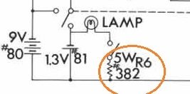
My model is different from yours, but I have the diagram of your model. And the strange part is: if I have to believe what is in the drawing, then there is a really heavy 5 watt resistor between the contact and the lamp. And if I have read this diagram correctly, it goes to ground. But an opinion of someone with insight in electronics is needed here. lamp resistor.jpg
 

Christophe1

Member
Joined
Oct 28, 2021
Messages
30
Location
Belgium
Format
35mm
IIRC, I believe you can get a replacement bulb from Model Train Stores or online catalog supply houses.

My light is dead also, so I'll be interested in hearing what is used successfully and where a PDF schematic may be downloaded from, as well as the experiences other have in this vital operation which seems to be about the only hiccup in an otherwise flawless analog device on which so much depends.

Godspeed and Cheers,
Eli
Hello Eli, I already contacted some model builders (mody builders?)stores as well, but it seems unfindable. But thanks for the tip and I will keep you informed, also about any new discoveries about the circuit.
 
  • Christophe1
  • Deleted
  • Reason: posted to the wrong person

Christophe1

Member
Joined
Oct 28, 2021
Messages
30
Location
Belgium
Format
35mm
IIRC, I believe you can get a replacement bulb from Model Train Stores or online catalog supply houses.

My light is dead also, so I'll be interested in hearing what is used successfully and where a PDF schematic may be downloaded from, as well as the experiences other have in this vital operation which seems to be about the only hiccup in an otherwise flawless analog device on which so much depends.

Godspeed and Cheers,
Eli
Here is the manual by the way. But I'm still convinced some pages are mssing.Because there is no listing of electronics components, strangely enough.
 

Attachments

  • 42796265-Pentax-Spotmeter-1-21-Repair-Manual.pdf
    751.5 KB · Views: 100

Christophe1

Member
Joined
Oct 28, 2021
Messages
30
Location
Belgium
Format
35mm
IIRC, I believe you can get a replacement bulb from Model Train Stores or online catalog supply houses.

My light is dead also, so I'll be interested in hearing what is used successfully and where a PDF schematic may be downloaded from, as well as the experiences other have in this vital operation which seems to be about the only hiccup in an otherwise flawless analog device on which so much depends.

Godspeed and Cheers,
Eli
This is another circuit diagram, found on the site of Mike Butkus. Someone drew and redesigned the circuit for the Spotmeter 1/21.
 

Attachments

  • pentax_asahi_spotmeter_diagram.pdf
    790.3 KB · Views: 135

BrianShaw

Member
Joined
Nov 30, 2005
Messages
16,597
Location
La-la-land
Format
Multi Format
I’m not an electrical engineer so can’t explain, but similar phenomenon when using battery adapter with Canonet camera. Meter and shutter work properly with the adapter but the battery test light doesn’t.
 
OP
OP
Donald Qualls

Donald Qualls

Subscriber
Joined
Jan 19, 2005
Messages
12,327
Location
North Carolina
Format
Multi Format
My model is different from yours, but I have the diagram of your model. And the strange part is: if I have to believe what is in the drawing, then there is a really heavy 5 watt resistor between the contact and the lamp. And if I have read this diagram correctly, it goes to ground. But an opinion of someone with insight in electronics is needed here. View attachment 289522

The 5W rating seems odd, given it's apparently only accepting current from a single mercury cell, but the relevant value is the resistance. This is a current limiter for the "grain of wheat" bulb, and if the 382 beside the component is the resistance, it'll pass only a couple milliamps. I'm not sure what the rating is on the bulb in this circuit -- neither voltage nor current -- but grain of wheat bulbs are commonly rated for 1 to 1.5 V and a hundred milliamps or so.

However, the other switch visible in that clip may connect to the 9V booster supply, making the lamp available only when the booster is connected and protecting the lamp from excessive current from that supply; 382 ohms would then pass around 25 mA, which is enough to give a yellowish glow from a 100 mA rated bulb, not to mention run the filament cool enough to last virtually forever. The resistor is still massively overrated (a fresh 9V alkaline battery can barely supply 5W when doing nothing else), but too big is better than too small, and the next smaller common rating, 2W, would be too small.
 

Christophe1

Member
Joined
Oct 28, 2021
Messages
30
Location
Belgium
Format
35mm
The 5W rating seems odd, given it's apparently only accepting current from a single mercury cell, but the relevant value is the resistance. This is a current limiter for the "grain of wheat" bulb, and if the 382 beside the component is the resistance, it'll pass only a couple milliamps. I'm not sure what the rating is on the bulb in this circuit -- neither voltage nor current -- but grain of wheat bulbs are commonly rated for 1 to 1.5 V and a hundred milliamps or so.

However, the other switch visible in that clip may connect to the 9V booster supply, making the lamp available only when the booster is connected and protecting the lamp from excessive current from that supply; 382 ohms would then pass around 25 mA, which is enough to give a yellowish glow from a 100 mA rated bulb, not to mention run the filament cool enough to last virtually forever. The resistor is still massively overrated (a fresh 9V alkaline battery can barely supply 5W when doing nothing else), but too big is better than too small, and the next smaller common rating, 2W, would be too small.
I have replaced the resistor in my spotmeter with a 80-something Ohm one, and the contact with a micro switch, a rather tricky work,
but it is working now and better than before.
The problem remains however that if you want to point the meter in the dark to a surface (or towards a dark surface) for measurement,
you still can't see the 'aiming circle' because the illuminator goes only up to number 8 or so on the scale. I think that is a bit of a design flaw, but anyway.
The circuit of the Pentax Spotmeter V seems , besides the lamp sub-circuit, rather complex by the way, much more than the earlier versions with only passive components I gather.
 
Photrio.com contains affiliate links to products. We may receive a commission for purchases made through these links.
To read our full affiliate disclosure statement please click Here.

PHOTRIO PARTNERS EQUALLY FUNDING OUR COMMUNITY:


Ilford ADOX Freestyle Photographic Stearman Press Weldon Color Lab Blue Moon Camera & Machine
Top Bottom