Reciprocity misbehavior.

Double exposure.jpg

H
Double exposure.jpg

  • 0
  • 0
  • 77
RIP

D
RIP

  • 0
  • 2
  • 101
Sonatas XII-28 (Homes)

A
Sonatas XII-28 (Homes)

  • 1
  • 1
  • 103
Street with Construction

H
Street with Construction

  • 1
  • 0
  • 106

Recent Classifieds

Forum statistics

Threads
199,328
Messages
2,789,757
Members
99,874
Latest member
fauthelisa
Recent bookmarks
0

Lee L

Member
Joined
Nov 17, 2004
Messages
3,281
Format
Multi Format
cao said:
I've seen reciprocity failure written as RF and RLF. I meant to save typing rather than mislead. I'll be sure to define stuff more carefully now.
Caught me off guard too. ;-)

When I saw RF, my first thought was radio frequency, but in the context of photography, I thought rangefinder. I did eventually scratch my head long enough to get RF to fit the context. Sometimes I'm slow on the uptake.
When talking reciprocity failure I've seen reference to HIRF, for high intensity reciprocity failure (when using that megawatt flash with 1/100,000 second duration) and LIRF, for low intensity reciprocity failure, when you have to go to long exposure times because of low light intensity. I've just not seen RF alone in that context.
I'm trying to come to terms (mathematically) with calculating the compounding of reciprocity failure when one Zone is adjusted with the Gainer formula and the others are allowed to fall accordingly. Just how much "expansion" (in Zone System terms) does reciprocity provide at given exposure times with a given Bond-Gainer film factor? I believe this is what "cao" is after. I'm not that great at math, but I'll post if I come up with anything useful.

Lee
 

cao

Member
Joined
Oct 5, 2004
Messages
188
Format
35mm
Lee L said:
Just how much "expansion" (in Zone System terms) does reciprocity provide at given exposure times with a given Bond-Gainer film factor? I believe this is what "cao" is after.
Lee

Yes indeed I am. I also think the expansion might not be uniform across the zones, so you might get different densities from a normal exposure from one corrected out a long time. I see this as a potential creative choice. In my case, I'm shooting some macros of highly polished aluminum objects, and I see a potential for bending the film curve as a way to give different looks to the highlights. That is, I want to use LIRF as a tool rather than something to curse.
 
OP
OP
gainer

gainer

Subscriber
Joined
Sep 20, 2002
Messages
3,699
cao said:
Yes indeed I am. I also think the expansion might not be uniform across the zones, so you might get different densities from a normal exposure from one corrected out a long time. I see this as a potential creative choice. In my case, I'm shooting some macros of highly polished aluminum objects, and I see a potential for bending the film curve as a way to give different looks to the highlights. That is, I want to use LIRF as a tool rather than something to curse.
I don't recall Howard Bond saying anything that would imply Zone expansion. Certainly Ilford did not over the range of 0 to 35 seconds indicated time which by their adjustment resulted in 200 second exposure. Zone expansion would appear as a reduction of contrast index, which Ilford would surely have pointed out. Perhaps we should think of the zones as influenced only by relative light intensity once the exposure to record Zone I is applied.

From what I have read, Ansel Adams compared visual zones to audible tones. Both are logarithmic functions, as are many things we can sense. We have seen the term Zones used as if it were a characteristic of film first and then of vision. His object was to get the Zones that he saw to appear on paper, which is manifestly impossible, but has been approximated by artists for centuries.

I digress, as usual. In the long run, I do not think RF will do this fooling of the eye for us. There will still be dodging and burning of wide range scenes that can when done well make one want to squint at specular reflections reproduced on paper while still being able to see into deep shadows that we could not see in real life.
 
OP
OP
gainer

gainer

Subscriber
Joined
Sep 20, 2002
Messages
3,699
In case anyone is interested, I have a graph that shows how the equation I found fits the Ilford data as found in www.ilford.com. I'm going to try to attach it. If it works, you will see the curve with numbers on both sides every 5 second of measured time. On the left are the values I measured from an enlarged copy of the graph. On the right are the numbers I calculated using a film factor of 0.51.

Here goes nothing!
 

Attachments

  • ILFORD_RF.gif
    ILFORD_RF.gif
    34.6 KB · Views: 268

Lee L

Member
Joined
Nov 17, 2004
Messages
3,281
Format
Multi Format
Gainer factor for Kodak "standard" film corrections

And here's a conversion of the ancient Kodak chart for "standard" films to an equivalent Gainer factor, which is about 0.80. See the attached chart for the correspondence. For corrections up through 100 seconds of metered exposure, the Gainer method is within +/- 16% of the corrected Kodak times, about 1/6th stop. If you'd prefer to use the old Kodak standard:

adjusted time = 2.0124*(metered time^1.3894)

I got that from doing a curve fit to a set of old data I got in the 1970s. It's essentially a perfect match to the "standard" film reciprocity curve that Kodak still has in all the E-31 Technical data sheets, and the equation fits with an R^2 of 1.0 to the computer printout I have with 1 second increments from 1 to 100.

Lee
 

Attachments

  • Gainer+KodakStd.png
    Gainer+KodakStd.png
    5.7 KB · Views: 192
OP
OP
gainer

gainer

Subscriber
Joined
Sep 20, 2002
Messages
3,699
The true beauty of this serendipitous discovery is that all B&W films seem to share the same basic variation with indicated time, differing only in one constant for each different film. This is still empirical, though someone may have a theory about it. But it certainly saves a lot of experimental drudgery when you don't know how to correct a new film. One exposure series based on the same indicated exposure time can pretty well nail down the film factor at that indicated time. and one more calculated exposure for a different long indicated exposure can tell you if the method indeed does work for that film. If it does, then you've got it made.

When I began as an aeronautical research engineer at NACA I learned the value of the different kinds of graph paper when you don't have a theory or the theory doesn't work. If it's not linear, try semi-log. If that doesn't work, try log-log.
 

Lee L

Member
Joined
Nov 17, 2004
Messages
3,281
Format
Multi Format
Reciprocity failure as "expansion"

Here's my thinking on this, which jibes with other things I've read in the past, and which I _have not tested_ in the real world. It agrees in principle with the information from Covington and others that I've read, and in general with the adjusments in development suggested by Kodak and others. Ryuji Suzuki indicates increased contrast as well at: http://silvergrain.org/Photo-Tech/reciprocity.html which is worthwhile reading if you're concerned about reciprocity failure. He specifically addresses the problem of increased contrast, and uses a polynomial expression for the Covington/Schwarzschild exponent, but doesn't say exactly what it is. If I'm reading it correctly, it might be a third order polynomial.

So here was my thought process:

Say you have a scene which has a medium gray and important detail at -2 stops and + 2 stops from the gray card (or incident reading). Without accounting for reciprocity they meter at 64 seconds, 16 seconds, and 4 seconds. With Ilford's recommended 0.51 film factor, that converts to 490 seconds, 61 seconds, and 8.8 seconds using the Gainer formula. The ratios are no longer 0.25/1/4, but become .125/1/6.95 after correction, so that an exposure at the corrected medium gray exposure of 61 seconds is underexposed below that point on the "tonal scale" and overexposed above it. In this instance, 2 stops under becomes 3 stops under and 2 stops over becomes 2.8 stops over. So in Zone system terms, Zone III has dropped to Zone II and Zone VII has risen almost a full stop to Zone VIII. This is caused by doing the exposure compensation for medium gray, which undercompensates for darker areas and overcompensates in lighter areas. So reciprocity itself is introducing a form of "expansion", and reduced development can, to some degree, be used to "contract" that expansion back into a printable range.

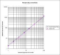
I have done a little spreadsheet that's does this calculation for me, and I can plug in a film factor and three different exposure times to see what happens to the range from -4 to + 5 stops from medium gray in 1 stop steps. It plots a little graph with a line for each of the exposure times, showing how the range of tones changes with extended exposures. Interestingly enough, if you plug in the numbers for TMAX and look at the results relative to the information posted here for development changes with extended exposures by Will S, you get a reasonable match.
These calculations use the medium gray exposure time for the reciprocity corrections using the Gainer formula, but other values away from medium gray could be used as well. The included chart allows you to view the effect on exposure areas at -4 to +5 stops from medium gray. The changes are calculated by adjusting the exposure for medium gray and comparing the required adjustments for other tones at 1 stop intervals, then taking the ratio between the adjustments required for other tones and the adjusted gray tone time. That ratio is converted to stops and plotted. The black "standard" line is the standard 1:2 ratio per stop to be used as a baseline for comparison. The attached chart uses TMX and the Gainer factor of 0.069 determined from the Bond article.

This is at least a place to start. I have a nagging feeling that I'm not completely taking care of the compounded effects with this method, so I have to give it some more thought. I'm posting it as a way to stimulate thoughts and comments, not as a final answer to the question.

Lee
 

Attachments

  • ReciprocityExpansion.pdf
    43.9 KB · Views: 528

Kirk Keyes

Member
Joined
Jun 17, 2004
Messages
3,234
Location
Portland, OR
Format
4x5 Format
gainer said:
When I began as an aeronautical research engineer at NACA I learned the value of the different kinds of graph paper when you don't have a theory or the theory doesn't work. If it's not linear, try semi-log. If that doesn't work, try log-log.

I had a friend point out in college that even the crappiest of data sets can sometimes look great when plotted on log-log paper. It's true!

Kirk - www.keyesphoto.com
 
OP
OP
gainer

gainer

Subscriber
Joined
Sep 20, 2002
Messages
3,699
Lee, Howard did not find any significant increase in contrast.
This is a quote from Howard Bond's article in Photo Techniques Magazine.

"In the past, films typically yielded increased density ranges with long exposures. The extra exposure that would render Zone III as planned was less needed in the high zones, so they were elevated, increasing the density ranges of negatives. This situation is now much improved. At 240 seconds indicated, T-Max 400 and 100 Delta showed no elevation of Zone VIII. Tri-X was up slightly, but the elevation was only slightly more than the typical variation from one attempt to another. Zone VIII was up about 2/3 zone with HP-5+ and T-Max 100. Stating an elevation in terms of zones is very approximate, since the width of a zone (expressed as a range of negative densities) varies greatly with development."

As you see, the effect of long exposures on the density range from Zone III to Zone VIII is much less than on the the exposure time to achieve a Zone III density with normal development.
 

Kirk Keyes

Member
Joined
Jun 17, 2004
Messages
3,234
Location
Portland, OR
Format
4x5 Format
I did some film testing this last summer, and I believe I saw this effect of increased contrast with 4 films at 240 seconds - BFP 200, FP4+, 320TXT, and 100TMX - the current version of each of those films. The lower zones were significantly lower in density as I had expected from my understanding of reciprocity effects.

I also ran Fuji Acros 100 and I really had to look hard to visually tell which film was at 1 sec. and which was at 240. Glad I creased the corner of one of those two films.

If you are doing long exposure B&W, I really suggest that you try some Acros.

Of course, since I haven't had time to do much data reduction on these tests, I really have to point out that this is anectodal evidence on my part.

Kirk - www.keyesphoto.com
 

Lee L

Member
Joined
Nov 17, 2004
Messages
3,281
Format
Multi Format
My "reciprocity expansion" spreadsheet is something I built not necessarily to perfectly reflect the real world, but more as a model with which I could "test" the effects of the reciprocity characteristics of different films and the length of exposure to see what the relative effects of those factors _might_ be on any reciprocity "expansion" of contrast, and against which to compare any empirical tests I do in the future. (Yeah, I read too much Henry James. ;-)

In other words, I can graph the difference between the Bond data filter factor of 0.101 for HP5+ and the Ilford chart factor of 0.51, and do it at different exposure lengths while monitoring generalized contrast effects. I don't expect it to be deadly accurate, just generally indicative, providing a visualization of the concepts rather than hard data to shoot from and expect to print on grade 2.0001 paper. The spreadsheet does agree with the Bond tests in indicating less expansion of contrast with newer films compared to the older emulsions.

I really could have used the information we've been swapping here when I was doing some quick pinhole work last spring with a chart based on the generic film charts and got some really overexposed XP2 negatives. Luckily, I can reshoot.

I've heard the same things that Kirk Keyes mentions about Acros having very low reciprocity failure. I have some on hand to try. See the chart on the Ryuji Suzuki web page I mentioned earlier to see how it compares to several other films.

Lee
 

Kirk Keyes

Member
Joined
Jun 17, 2004
Messages
3,234
Location
Portland, OR
Format
4x5 Format
Lee, please do check your Acros - I've also seen mention of it's excellent long exposure properites. I was using an enlarger and step wedge, and I wasn't able to do any longer tests since I didn't have time to enclose the enlarger head to cut down more on the stray light... but I would like to see results from someone that obviously understands the subject.

Kirk
 

Lee L

Member
Joined
Nov 17, 2004
Messages
3,281
Format
Multi Format
Acros reciprocity number

Kirk Keyes said:
Lee, please do check your Acros - I've also seen mention of it's excellent long exposure properites. I was using an enlarger and step wedge, and I wasn't able to do any longer tests since I didn't have time to enclose the enlarger head to cut down more on the stray light... but I would like to see results from someone that obviously understands the subject.

Kirk

Kirk,

I'm just beginning to understand. There are lots of people who know a lot more than I.

It may be a while before I run the Acros, (I've got a number of films I want to test in several developers, having been out of the darkroom a while) but I've calculated the Acros film factor for the Gainer formula from the mfgrs data sheet and the chart at Ryuji Suzuki's site, and it's in the neighborhood of 0.019 if that will help you. The data sheet is at: http://tinyurl.com/689a8 (sorry, the original was very long and had a sessionid) It basically says to open up 1/2 stop for any exposure between 120 and 1000 seconds.

I'll post when I get something myself. I'll definitely load the Acros when I need long times. I'd try it for astrophotos if it didn't drop off the map below 650nm, which makes it pointless for one of the common wavelengths in nebulae emitted by hydrogen. It might work fine for some wide constellation shots without nebulae.

Lee
 
OP
OP
gainer

gainer

Subscriber
Joined
Sep 20, 2002
Messages
3,699
I'll post when I get something myself. I'll definitely load the Acros when I need long times. I'd try it for astrophotos if it didn't drop off the map below 650nm, which makes it pointless for one of the common wavelengths in nebulae emitted by hydrogen. It might work fine for some wide constellation shots without nebulae.

Lee

I think you meant to say above 650 nm. Below 650 is most of the visible range. Hydrogen IIRC is in the red with lines above 650. I'm pretty sure Acros records visible light.
 

Lee L

Member
Joined
Nov 17, 2004
Messages
3,281
Format
Multi Format
gainer said:
I think you meant to say above 650 nm. Below 650 is most of the visible range. Hydrogen IIRC is in the red with lines above 650. I'm pretty sure Acros records visible light.

Sorry if I was unclear. Perhaps I should have phrased it "before reaching 650nm". I was mentally going "up" in wavelength as opposed to frequency, a so the drop off in sensitivity in that case would be "before" or "below" 650nm. In any case, as you've noted, Acros is meant for the visible spectrum (at least most of it), and sensitivy doesn't extend to 650nm or "above". The IR folks would have a ball with it if it "saw" only above 650nm. And yes, you recall correctly, the H-alpha line is near 656nm.

Lee
 
Last edited by a moderator:
OP
OP
gainer

gainer

Subscriber
Joined
Sep 20, 2002
Messages
3,699
gainer said:
In case anyone is interested, I have a graph that shows how the equation I found fits the Ilford data as found in www.ilford.com. I'm going to try to attach it. If it works, you will see the curve with numbers on both sides every 5 second of measured time. On the left are the values I measured from an enlarged copy of the graph. On the right are the numbers I calculated using a film factor of 0.51.

Here goes nothing!

I got that film factor right in the text, 0.51, but spelled it 0.051 on the figure. The Ilford film factor is about 5 times what Howard Bond found in his experiments, but the shape of the curve is dead on.
 

Ryuji

Member
Joined
Jan 15, 2005
Messages
1,415
Location
Boston, MA
Format
Multi Format
gainer said:
The true beauty of this serendipitous discovery is that all B&W films seem to share the same basic variation with indicated time, differing only in one constant for each different film.

Reciprocity failure occurs because of inefficiencies in producing latent image centers from photoelectrons, and this inefficiency changes depending on the intensity of light irradiation. This phenomenon can be modified by different halide profiles of core-shell structures as well as different doping profiles at different depth of such crystals. Then there are different ways to chemically sensitize the emulsion. Reciprocity failure also varies depending on the crystal size, habit, etc. For example, cubic (100) AgCl tends to have more pronounced high intensity reciprocity failure if not combined with these methods to modify the behavior. It is typically seen as a long shoulder with the same toe. In case of (100) AgCl, a very well known emulsion stabilizing agent can improve the efficiency of latent image formation. After all, even a simple sulfur or gold sensitization can change the reciprocity failure. There are zillions of factors influencing this phenomenon.

Just because some manufacturer publishes one correction chart for many of their products, it is pretty inappropriate to assume the underlying mechanism is the same.
 
OP
OP
gainer

gainer

Subscriber
Joined
Sep 20, 2002
Messages
3,699
.

Just because some manufacturer publishes one correction chart for many of their products, it is pretty inappropriate to assume the underlying mechanism is the same.[/QUOTE]

Ryuji, you could at least be gracious enough to read the article in Photo Techniques, Sept/Nov 2003 called "Reciprocal Trade Disagreement." You will see that I did NOT rely on manufacturer's so-called data, but on experimental determinations of reciprocity correction done by Howard Bond and published the previous issue. Theories are for the purpose of reducing observed behavior to first principles, as Aristotle said. I made no claim to have done that. I found an order in the data that someone might find a theory to explain, but in the meantime, I claimed it to be nothing more than an empirical relationship that fit the available data to within 1/3 f-stop over the range. I used the least-square criterion for the fit.
 
OP
OP
gainer

gainer

Subscriber
Joined
Sep 20, 2002
Messages
3,699
Kirk Keyes said:
Lee, please do check your Acros - I've also seen mention of it's excellent long exposure properites. I was using an enlarger and step wedge, and I wasn't able to do any longer tests since I didn't have time to enclose the enlarger head to cut down more on the stray light... but I would like to see results from someone that obviously understands the subject.

Kirk
Here's a suggestion for anyone using an enlarger for tests where stray light can be a problem. Instead of enclosing the head, build a sort of tent out of matte board from the lens to the baseboard, with a flap so you can change stuff. If you need to change magnification, make the tent flexible. This works pretty well for a lot of cases, and has the advantage that the head will not overheat.
 

Kirk Keyes

Member
Joined
Jun 17, 2004
Messages
3,234
Location
Portland, OR
Format
4x5 Format
gainer said:
build a sort of tent out of matte board from the lens to the baseboard, with a flap so you can change stuff.

Patrick - I thought of this as well. There are two options, seal up the head to eliminate tray light from the head, or seal up the film to minimize stray light from hitting the film.

I figured that sealing the head would be better as I didn't want any potential stray light from the lens (i.e. any flare) bouncing back onto the film as it relected off the lens tent. I actually figured I would enclose the head, which really only need to be turned on for a few seconds before and after the exposure, so no need to worry about it overheating, and then a partial "tent" extending from the easal up several inches above the film. More like a fence, than a tent.

Anyway, that's what I was thinking of.
 
OP
OP
gainer

gainer

Subscriber
Joined
Sep 20, 2002
Messages
3,699
This is a general comment on this and other threads as the occasion might arise. Beware of theories. It was said of sigmund Freud that he could explain everything, but could predict nothing. Kurt Godel (There should be an umlaut over the "o") proved that any set of axioms at least as rich as arithmeticis either incomplete or inconsistent. There are limits to our theories. Art is real. Science is imaginary. It is an invention of the human mind which is an invention of nature. The results of experiments are real, always erroneous to some extent, but they are the way we control our environment. We try to find order in them so that we can predict changes in the environment, whether it is the weather or the exposure to give our next photograph. The models we use are usually empirical. When we have a successful empirical model, some among us will try to find a more fundamental basis for it. We eventually arrive at the consequences of Godel's theorem and sit around arguing about which incomplete and/or inconsistent set of axioms is THE one. We are all wrong. Report the observations and the empirical curve fit. Theories are alright, but don't hold them to be infallible. Thanks for having me.
 
OP
OP
gainer

gainer

Subscriber
Joined
Sep 20, 2002
Messages
3,699
Kirk Keyes said:
Patrick - I thought of this as well. There are two options, seal up the head to eliminate tray light from the head, or seal up the film to minimize stray light from hitting the film.

I figured that sealing the head would be better as I didn't want any potential stray light from the lens (i.e. any flare) bouncing back onto the film as it relected off the lens tent. I actually figured I would enclose the head, which really only need to be turned on for a few seconds before and after the exposure, so no need to worry about it overheating, and then a partial "tent" extending from the easal up several inches above the film. More like a fence, than a tent.

Anyway, that's what I was thinking of.
I was thinking of the long exposures sometimes required for reciprocity tests. Things get pretty hot after 5 minutes or so with the vents blocked. Of course, a little more elaborate head cover could allow ventilation as well as adequate light sealing. My problem was light leaking around the negative carrier where it was difficult to cover.

I used black matte board with the black side inside to cut down those reflections you are concerned about, but I am pretty well stuck with one head position.
 

Kirk Keyes

Member
Joined
Jun 17, 2004
Messages
3,234
Location
Portland, OR
Format
4x5 Format
yes - just a box with a baffle for air flow for the head is really all that's needed. I have a Saunders 4500 with a good fan. But, yeah, I forgot about the several minutes thing there!
 
OP
OP
gainer

gainer

Subscriber
Joined
Sep 20, 2002
Messages
3,699
Ryuji said:
Reciprocity failure occurs because of inefficiencies in producing latent image centers from photoelectrons, and this inefficiency changes depending on the intensity of light irradiation. This phenomenon can be modified by different halide profiles of core-shell structures as well as different doping profiles at different depth of such crystals. Then there are different ways to chemically sensitize the emulsion. Reciprocity failure also varies depending on the crystal size, habit, etc. For example, cubic (100) AgCl tends to have more pronounced high intensity reciprocity failure if not combined with these methods to modify the behavior. It is typically seen as a long shoulder with the same toe. In case of (100) AgCl, a very well known emulsion stabilizing agent can improve the efficiency of latent image formation. After all, even a simple sulfur or gold sensitization can change the reciprocity failure. There are zillions of factors influencing this phenomenon.

Just because some manufacturer publishes one correction chart for many of their products, it is pretty inappropriate to assume the underlying mechanism is the same.
Ryuji, let me ask an earnest, honest question. I look at the equation that describes the current through a junction diode as a function of the voltage across it. I have used this in analog computing, and it is quite accurate for making a logarithmic amplifier over a considerable range of 3 to 4 decades when I use the collector-base junction of a silicon transistor. The model equation does not fit reciprocity, as it is the kind of eponential equation that plots as a line on log paper, but the fact that Boltzmann's constant and absolute temperature are the factors that shape the response and it is pretty well constant for high and low current diodes. I think the voltage drop across the diode is dependent on the area of the junction (at least). When I read about reciprocity, I see many things that remind me of that diode equation. Why should there not be a similar type of thing here? One part of the equation with its characteristic response and another which describes the magnitude of the response?
 

Ryuji

Member
Joined
Jan 15, 2005
Messages
1,415
Location
Boston, MA
Format
Multi Format
Gainer, you are bringing up irrelevant issue here. What you are talking about is forward voltage drop at the pn junction. Reciprocity law failure is mostly due to the loss of the carrier or unstable latent subimage. All these are described on my webpage and references therein in greater details. The former is negligible in the exponential region of the pn junction, and the latter concept does not exist in pn junction.
 
Photrio.com contains affiliate links to products. We may receive a commission for purchases made through these links.
To read our full affiliate disclosure statement please click Here.

PHOTRIO PARTNERS EQUALLY FUNDING OUR COMMUNITY:


Ilford ADOX Freestyle Photographic Stearman Press Weldon Color Lab Blue Moon Camera & Machine
Top Bottom