Nikon Coolscan 9000 not switching on - presume power supply issue.

Recent Classifieds

Forum statistics

Threads
197,577
Messages
2,761,351
Members
99,406
Latest member
filmtested
Recent bookmarks
0

Tom Kershaw

Subscriber
Joined
Jun 5, 2004
Messages
4,972
Location
Norfolk, United Kingdom
Format
Multi Format
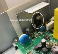
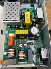
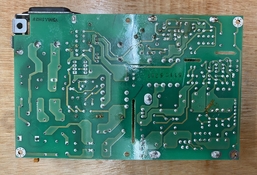
My Coolscan 9000 refused to switch on a few days ago, after having been used as normal the previous day. This website: https://www.shtengel.com/gleb/Nikon_8000_9000_power_supply.htm - suggests a particular integrated circuit is usually at fault.
https://www.semicon.sanken-ele.co.jp/sk_content/str-w67xxseries_an_en.pdf - if anyone else has suffered this problem on Photrio - is there anything else that is likely to have gone wrong? - the continuity of the internal fuse is fine.

I've seen recommendations for https://lincolnscan.co.uk/ as a repair option but it would be useful to have some more general idea.
 

Attachments

  • NikonLS9000_SankenSTRW6756.jpg
    NikonLS9000_SankenSTRW6756.jpg
    379.9 KB · Views: 73
Last edited:

koraks

Moderator
Moderator
Joined
Nov 29, 2018
Messages
20,935
Location
Europe
Format
Multi Format
is there anything else that is likely to have gone wrong? -
Assuming the actual power switch works OK (test it with a continuity meter):

Start by checking the electrolytic capacitors; observe if any have a bulging cap and/or have started to ooze electrolyte either from the cross shape at the top, or along the legs. If so, these will need to be replaced.

The controller & switching IC is a logical item to replace; you might just give that a try and see if it helps.
 
OP
OP

Tom Kershaw

Subscriber
Joined
Jun 5, 2004
Messages
4,972
Location
Norfolk, United Kingdom
Format
Multi Format
Assuming the actual power switch works OK (test it with a continuity meter):

Start by checking the electrolytic capacitors; observe if any have a bulging cap and/or have started to ooze electrolyte either from the cross shape at the top, or along the legs. If so, these will need to be replaced.

The controller & switching IC is a logical item to replace; you might just give that a try and see if it helps.

Thanks. I'll take a closer look. I've attached a photo showing the general visual condition of the power supply.
 

Attachments

  • NikonLS9000_general_psu1.jpg
    NikonLS9000_general_psu1.jpg
    731.6 KB · Views: 76

koraks

Moderator
Moderator
Joined
Nov 29, 2018
Messages
20,935
Location
Europe
Format
Multi Format
It looks excellent. There was a massive problem with electrolytic capacitors around the time this unit was manufactured, however it clearly does not affect your power supply. I'd put my money on the IC you mentioning having given up the ghost after 20 years of service.
 

koraks

Moderator
Moderator
Joined
Nov 29, 2018
Messages
20,935
Location
Europe
Format
Multi Format
- this article suggests the problem persisted for a several years. https://en.wikipedia.org/wiki/Capacitor_plague

Yes, indeed; I had to deal with it back then quite extensively. I've replaced many capacitors on computer mainboards, which was an application where the problem popped up early on given the high ripple current loads and high temperatures the caps are subject to in such a context.

What makes me state with confidence that this particular concern is not applicable to your power supply is the lack of visible damage (no 'popped cans') and the fact that if the capacitors in your scanner would have been from the many affected batches, the problems would have popped up about a decade ago at the latest.

Mind you, ultimately, all electrolytic capacitors fail. But most will take many decades before that moment comes.
 
OP
OP

Tom Kershaw

Subscriber
Joined
Jun 5, 2004
Messages
4,972
Location
Norfolk, United Kingdom
Format
Multi Format
What makes me state with confidence that this particular concern is not applicable to your power supply is the lack of visible damage (no 'popped cans') and the fact that if the capacitors in your scanner would have been from the many affected batches, the problems would have popped up about a decade ago at the latest.

I've just had another look and cannot see any visible damage. I also checked the continuity of the power switch and that is fine.
 

koraks

Moderator
Moderator
Joined
Nov 29, 2018
Messages
20,935
Location
Europe
Format
Multi Format
Good work! Looks like the next step would be to get one of those IC's. I checked earlier today; they're around 1 eurodollarpound/pc if you get a handful from China.
 

koraks

Moderator
Moderator
Joined
Nov 29, 2018
Messages
20,935
Location
Europe
Format
Multi Format
Yeah, if this is your first time doing work on a PCB, you'll have to learn a thing or two. Maybe get your hands on some old/broken equipment and practice on that. Or - see if you can find someone near you to do this for you.

The easiest way will be if you cut the leads of the old IC before trying to desolder them. Then get some desoldering braid and flux, and use that to suck out the tin from the contacts. At that point, the cut pins should wiggle out of the holes fairly easily - provided you can get the tin sucked out well enough (from both sides of the PCB!) With the pins out, clean up the holes a little more with the desoldering braid so they're nice and open. Then slide in the new IC and solder the joints.

The hard part is removing the existing pins from the PCB so as not to damage the PCB and leave clean through-holes for the new IC to fit into.
 

tokam

Subscriber
Joined
Nov 7, 2008
Messages
585
Location
Sydney, Aust
Format
Multi Format
Looks like a slow-blow fuse in the bottom of the picture. Have you checked continuity across it? I had a failed power supply for a Leitz Focomat V35 enlarger with a dead fuse. You can't check by visual inspection.
 

reddesert

Member
Joined
Jul 22, 2019
Messages
2,319
Location
SAZ
Format
Hybrid
There is supposedly a fairly active group, I think Facebook group, on repair of these scanners. You might want to ask there if there are any tests you can do to check whether it's the regulator IC, before desoldering anything from the PC board, especially if you don't have a lot of experience with that.
 
OP
OP

Tom Kershaw

Subscriber
Joined
Jun 5, 2004
Messages
4,972
Location
Norfolk, United Kingdom
Format
Multi Format
There is supposedly a fairly active group, I think Facebook group, on repair of these scanners. You might want to ask there if there are any tests you can do to check whether it's the regulator IC, before desoldering anything from the PC board, especially if you don't have a lot of experience with that.

Yes. I'll have a look at that group.
 

forest bagger

Subscriber
Joined
Nov 9, 2023
Messages
250
Location
Germany
Format
DSLR
- perhaps I should look up a soldering tutorial on YouTube...
That is an integrated circuit with a powerful switching transistor, which I wanted to replace when my Coolscan 9000 stopped working 10 years ago.
The main switching transistor in that IC had a shortcut, I found this IC on the web and I replaced it.
After reassembling the coolscan 9000 the IC went shortcut again, immediately after power on.
So I asked some technician who has much knowing of switching power supplies for help.
He assumed that the power transformer had a shortcut within its coils what caused the shortcut in the IC.
So I searched the web for a complete power supply for the coolscan 9000 and found the last one in Russia for some hundred US-$.
That was about 9 years ago and I don't think there will be any parts of a coolscan 9000 available today.
 

koraks

Moderator
Moderator
Joined
Nov 29, 2018
Messages
20,935
Location
Europe
Format
Multi Format
After reassembling the coolscan 9000 the IC went shortcut again, immediately after power on.

Yep, there's always the question why the IC blows up. Then again, if the transistor was shorted out, you would have also had a blown fuse, no? The transistor switches the primary of the transformer. If that's shorted and the transistor shorts, the fuse would blow as well. Did this happen on your device?

In any case, there's always the chance that the IC just died for no particular reason. Replacing it is often the cheapest diagnostic. This is one reason to purchase a handful, not just one (the other reason being that they're generally a lot cheaper that way).
 
OP
OP

Tom Kershaw

Subscriber
Joined
Jun 5, 2004
Messages
4,972
Location
Norfolk, United Kingdom
Format
Multi Format
Yep, there's always the question why the IC blows up. Then again, if the transistor was shorted out, you would have also had a blown fuse, no? The transistor switches the primary of the transformer. If that's shorted and the transistor shorts, the fuse would blow as well. Did this happen on your device?
- my scanner simply would not switch on one day, there was no "bang" or sudden loss of power.
 

koraks

Moderator
Moderator
Joined
Nov 29, 2018
Messages
20,935
Location
Europe
Format
Multi Format
- my scanner simply would not switch on one day, there was no "bang" or sudden loss of power.

I understand; neither would be expected in case of a blown fuse within the PCB.
My apologies, though, as I was wondering specifically about @forest bagger's scanner. The fuse didn't blow on yours, so I don't expect the failure mode to involve a shorted transformer in your case.
 

forest bagger

Subscriber
Joined
Nov 9, 2023
Messages
250
Location
Germany
Format
DSLR
I remember that there was a resistor of some Ohms between the ground pin of the IC an the real ground of the circuit which was blown.
The picture in #1 shows it - the white rectangular thing in the right upper picture corner is it, I think.
 
OP
OP

Tom Kershaw

Subscriber
Joined
Jun 5, 2004
Messages
4,972
Location
Norfolk, United Kingdom
Format
Multi Format
I've done some more investigating and have removed the power supply board from the scanner. Attached is a photo of the underside of the board. All the resistors I've measured so far have been okay, although with a couple the measured resistance increased over time, assume this is related to contact between the probe(s) and component.
 

Attachments

  • NikonLS9000PSU_underside.jpg
    NikonLS9000PSU_underside.jpg
    1.5 MB · Views: 55

koraks

Moderator
Moderator
Joined
Nov 29, 2018
Messages
20,935
Location
Europe
Format
Multi Format
with a couple the measured resistance increased over time

This is usually due to a capacitance parallel to the measured resistance slowly charging, which affects the readings.

The PCB looks OK; I wouldn't have expected to see any damage here. It looks almost as if someone did some work on this unit at some point.
 
OP
OP

Tom Kershaw

Subscriber
Joined
Jun 5, 2004
Messages
4,972
Location
Norfolk, United Kingdom
Format
Multi Format
This is usually due to a capacitance parallel to the measured resistance slowly charging, which affects the readings.
I should probably check the voltage of all the capacitors then, I'm learning as I go here. The high voltage capacitors were at zero volts when tested.

The PCB looks OK; I wouldn't have expected to see any damage here. It looks almost as if someone did some work on this unit at some point.
I see what you mean, which is why I included the photo. However, I've owned the scanner from new in autumn 2006 and it hasn't been serviced previously by myself.
 

koraks

Moderator
Moderator
Joined
Nov 29, 2018
Messages
20,935
Location
Europe
Format
Multi Format
I should probably check the voltage of all the capacitors then

No, don't worry about this. The gist is just that measuring resistors (or any kind of component) within a circuit only works to an extent. There's not all that much you can do about that - or at least not much you need to do in this case.

As to the work on the PCB: this could just as well be a minor correction at the end of the assembly line; e.g. some joints that didn't come out nice from the reflow solder bath that they touched up manually. The board looks fine in any case.
 

MattKing

Moderator
Moderator
Joined
Apr 24, 2005
Messages
51,996
Location
Delta, BC Canada
Format
Medium Format
Check the wall plug :smile:.
 
Photrio.com contains affiliate links to products. We may receive a commission for purchases made through these links.
To read our full affiliate disclosure statement please click Here.

PHOTRIO PARTNERS EQUALLY FUNDING OUR COMMUNITY:


Ilford ADOX Freestyle Photographic Stearman Press Weldon Color Lab Blue Moon Camera & Machine
Top Bottom