Nikon Coolscan 9000 not switching on - presume power supply issue.

Cafe Art

A
Cafe Art

  • 6
  • 3
  • 77
Sciuridae

A
Sciuridae

  • 5
  • 2
  • 121
Takatoriyama

D
Takatoriyama

  • 6
  • 3
  • 134
Tree and reflection

H
Tree and reflection

  • 2
  • 0
  • 107

Recent Classifieds

Forum statistics

Threads
197,639
Messages
2,762,295
Members
99,426
Latest member
subtlelikeatrex
Recent bookmarks
0

koraks

Moderator
Moderator
Joined
Nov 29, 2018
Messages
20,983
Location
Europe
Format
Multi Format
It's hard to tell, but there are some traces of rosin flux on the board.
For something to bridge those copper fills it would have to penetrate the solder mask. There doesn't appear to be any damage to the mask however.
If this were my board, I'd wipe off whatever that copper colored stuff is and not worry about it.
 
OP
OP

Tom Kershaw

Subscriber
Joined
Jun 5, 2004
Messages
4,972
Location
Norfolk, United Kingdom
Format
Multi Format
This evening I confirmed there was no voltage present on the power supply output pins +5v, 15v etc. Unfortunately afterwards, while investigating the Sanken IC STRW6756 I managed to accidentally short the component and blow the internal fuse. Hopefully with no lasting damage to the board in general.

Another thing to note is that I found a resistor that gave no reading, but this may be down to my measuring technique, not sure.
 

Attachments

  • LS9000_R1.jpg
    LS9000_R1.jpg
    1.3 MB · Views: 56

mmerig

Member
Joined
Oct 9, 2012
Messages
201
Location
Teton Valley
Format
Medium Format
I agree with forest bagger about the "reddish pollution" being a possible bridge between the two conductor tracks. It's worth making sure there isn't a bridge there using an ohm meter or looking closely with a magnifying glass, or even scarping it with a finger nail to see if anything moves.
 

koraks

Moderator
Moderator
Joined
Nov 29, 2018
Messages
20,983
Location
Europe
Format
Multi Format
a resistor that gave no reading

Looks lik 4.7MegOhms. What's the range on your meter? They sometimes only go up to 2Meg. This resistor will look like an open circuit to such a meter.
It's not a critical resistor in any case, nor is it likely to be fried.

Hopefully with no lasting damage to the board in general.
Hard to tell for sure, but I don't really expect there to be any other damage than the fuse. If you're very unfortunate, you may have fried the HV rectifier, but let's not speculate for now.

a possible bridge between the two conductor tracks

You guys are forgetting about the solder mask. It's the green coating on the PCB. It's a very good insulator. Even if this contamination were something like copper grease (it kind of looks like it, although there's no reason whatsoever why it would be there), it still wouldn't bridge those copper pour areas.
 

forest bagger

Subscriber
Joined
Nov 9, 2023
Messages
250
Location
Germany
Format
DSLR
Unfortunately afterwards, while investigating the Sanken IC STRW6756 I managed to accidentally short the component and blow the internal fuse.
You test while power is on? Very courageous!
Besides - the power supply is intended to work properly under load.
You can replace the blown fuse and put AC power on: If it blows at once, you have a severe problem with the board.
 

mmerig

Member
Joined
Oct 9, 2012
Messages
201
Location
Teton Valley
Format
Medium Format
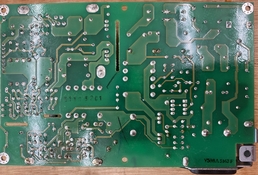
- the board has cleaned up well.
That's great. I was thinking the red was a scrape rather than a coating.

I have a Nikon Cool Scan V ED, and the power supply could be similar to the one you have.

It works fine, and I took the power supply board out to see if it works when not connected to rest of the scanner, and it does. There are load resistors mounted on the power supply board.

The loads to ground for the outputs are:

15 VDC 3.55 K ohms

-12 VDC 2.6 K

5 VDC 53

The load to ground changes somewhat when the power supply is connected, and they are, in the same order as above, 3.62 K, 1.33 K, and 55.7.

There is some high frequency ringing on the outputs (not unusual for switching power supplies). Here is an example for the 15 VDC output:

Nikon LS-50_2.JPG


The voltage division on the oscilloscope screen is 10 mV and the time division is 0.1 uS.


The -12 VDC had a similar pattern, and the 5 VDC had about half the voltage amplitude

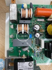
Be careful when working around the PSU when it is powered up. Notably, there is high voltage at the heatsink for an IC (the smaller heatsink, without the holes), as well as other exposed points. The small heatsink is the easiest one to touch by accident. The voltage on this heatsink drops to a few millivolts in about 1 second after the unit is powered off, but yours may not do this, and it is always good to be extra careful anyway.


This heatsink reaches 105 degrees F when at room temperature after a few minutes and stays at that temperature.
 
OP
OP

Tom Kershaw

Subscriber
Joined
Jun 5, 2004
Messages
4,972
Location
Norfolk, United Kingdom
Format
Multi Format
It works fine, and I took the power supply board out to see if it works when not connected to rest of the scanner, and it does. There are load resistors mounted on the power supply board.

The loads to ground for the outputs are:

15 VDC 3.55 K ohms

-12 VDC 2.6 K

5 VDC 53

The load to ground changes somewhat when the power supply is connected, and they are, in the same order as above, 3.62 K, 1.33 K, and 55.7.

Thank you for those values as a reference.
 
OP
OP

Tom Kershaw

Subscriber
Joined
Jun 5, 2004
Messages
4,972
Location
Norfolk, United Kingdom
Format
Multi Format
Update. I have replaced the fuse with a new one and I'm now getting good readings to spec from the power supply pins. I'll reassemble the scanner and report back. Odd as the original fuse had continuity, but perhaps was on the verge of failure?
 

koraks

Moderator
Moderator
Joined
Nov 29, 2018
Messages
20,983
Location
Europe
Format
Multi Format
That's an odd sequence of events, but hard to tell what exactly happened based on indirect observations. Either way, this is great news as it's evidently the easiest fix imaginable!
 
OP
OP

Tom Kershaw

Subscriber
Joined
Jun 5, 2004
Messages
4,972
Location
Norfolk, United Kingdom
Format
Multi Format
That's an odd sequence of events, but hard to tell what exactly happened based on indirect observations. Either way, this is great news as it's evidently the easiest fix imaginable!

Perhaps cleaning the underside of the power supply circuit board helped with an intermittent fault? Anyway, I've connected the scanner up to a Power Book G4 running NikonScan and it is all working.
 

reddesert

Member
Joined
Jul 22, 2019
Messages
2,323
Location
SAZ
Format
Hybrid
Another possibility is that there is a weak solder joint or connection (or switch internals) that was failing, got pushed back into contact while you were handling the board, and is now failing again. The solder joints all looked ok in the photo of the back of the board, but it is sometimes hard to see a bad one by inspection. I have occasionally found an amplifier or similar where a joint that once worked became unreliable due to (guessing) many thermal cycles.
 
OP
OP

Tom Kershaw

Subscriber
Joined
Jun 5, 2004
Messages
4,972
Location
Norfolk, United Kingdom
Format
Multi Format
Thanks for the comments on solder joints. Although my scanner is in excellent cosmetic / physical condition, and certainly was working well, it has seen plenty of use, with just the occasional break of several months, not put in storage for years etc.
 

Les Sarile

Member
Joined
Aug 7, 2010
Messages
3,415
Location
Santa Cruz, CA
Format
35mm
My Coolscan 9000 refused to switch on a few days ago, after having been used as normal the previous day. This website: https://www.shtengel.com/gleb/Nikon_8000_9000_power_supply.htm - suggests a particular integrated circuit is usually at fault.
https://www.semicon.sanken-ele.co.jp/sk_content/str-w67xxseries_an_en.pdf - if anyone else has suffered this problem on Photrio - is there anything else that is likely to have gone wrong? - the continuity of the internal fuse is fine.

I've seen recommendations for https://lincolnscan.co.uk/ as a repair option but it would be useful to have some more general idea.

In that shtengel website you showed, there is also a power supply repair shop link provided for what seems to be a reasonable repair cost of around $100 - www.power-medic.com
Unfortunately they're in Orange, CA USA. Maybe there's a power supply repair shop - or a general electronic repair shop, closer to you? I know repairing power supplies are probably not common as that is just not cost effective. Unfortunately I'm not aware of a direct replacement. Closest I know of is the original PC XT power supply but it is short one +15v output.
BTW, did you already check the voltages in the output connector CN1 that he provided the specs for?
 

koraks

Moderator
Moderator
Joined
Nov 29, 2018
Messages
20,983
Location
Europe
Format
Multi Format
Closest I know of is the original PC XT power supply but it is short one +15v output.

Well, in the way of alternatives, you could take any 12V SMPS and make the other voltages with buck converters. The physical fit will be the main challenge. If I were to do this, I'd start with a fairly small 12V unit and then add the other buck converters on a custom PCB to make everything fit in the original space.
Did something similar for my Minolta scanner, but it was much simpler since all it needs is 24V, so I just replaced the original unit with a generic Chinese one I had bought for another project.

In this case, I'd start by replacing the SMPS controller, although the intermittent nature of the problem is slightly worrying as it may point to the need for more thorough diagnosis.
 

Les Sarile

Member
Joined
Aug 7, 2010
Messages
3,415
Location
Santa Cruz, CA
Format
35mm
Well, in the way of alternatives, you could take any 12V SMPS and make the other voltages with buck converters. The physical fit will be the main challenge. If I were to do this, I'd start with a fairly small 12V unit and then add the other buck converters on a custom PCB to make everything fit in the original space.
Did something similar for my Minolta scanner, but it was much simpler since all it needs is 24V, so I just replaced the original unit with a generic Chinese one I had bought for another project.

In this case, I'd start by replacing the SMPS controller, although the intermittent nature of the problem is slightly worrying as it may point to the need for more thorough diagnosis.

No doubt intermittent problems are the worst and isolating the problem to the power supply or other would be a good start.

Good idea about starting with a 12V PS and adding buck converters to cover the rest. I wonder if the shtengel website is accurately identifying the output as, "3 outputs: +5V, -12.2V, and +15.5V (as usual +/- 5% tolerance)". I'm particularly skeptical of the tolerance of 5% as it applies to +5V but comfortable with it for the other two.

As far as it fitting within the case, I am a proponent of keeping the main heat generator outside the box. So it that means leaving it outside then so be it. PC TX power supplies are abundant, cheap, more than ample current and have been around so I wouldn't hesitate starting with one and a converter for +15.5.

Take safety precautions first as potentially lethal voltages are present when working with power supplies in the open. Replacing parts always with power off and circuits have had ample time to be discharged or grounded. As a long time tech, my suggestions for the quickest diagnosis of a power supply without schematics is checking presence of input voltage then the output voltages to be within tolerance and have minimum (millivolts) to no ripple under load. If there is ripple then start replacing all electrolytic caps starting with those closest to heatsinks. The controller IC STRW6756 is cheap and available everywhere and identified as a "common" problem so no hesitation replacing that too.
 

koraks

Moderator
Moderator
Joined
Nov 29, 2018
Messages
20,983
Location
Europe
Format
Multi Format
I am a proponent of keeping the main heat generator outside the box.

Another modern option would be to take a 100W USB-C PD laptop charger ($20-30 for a decent unit), configure it to 12V with little USB-C power decoy ($2) and use two buck converters to make 5V and 15V ($2 each). Add some cables etc. and you have a brand new power supply for $50. The buck converters could be placed inside the scanner's enclosure or in an external case if so desired.

ATX computer power supplies are indeed plentiful, especially on the second hand market, but over-dimensioned for this task and as a result bulky and often noisy. It'll work "in a pinch", as they say.

My personal preference would be to restore the original unit to working condition because the device will remain a self-contained box that way, but a replacement along the lines we're explored above might be quicker.
 

Les Sarile

Member
Joined
Aug 7, 2010
Messages
3,415
Location
Santa Cruz, CA
Format
35mm
My personal preference would be to restore the original unit to working condition because the device will remain a self-contained box that way, but a replacement along the lines we're explored above might be quicker.
My personal preference would also be to keep it near original maintaining that potential high resale value for sure! Having a quick cheap PS to isolate the problem is indeed beneficial.

BTW, are there still electronic repair shops over there?
 
Photrio.com contains affiliate links to products. We may receive a commission for purchases made through these links.
To read our full affiliate disclosure statement please click Here.

PHOTRIO PARTNERS EQUALLY FUNDING OUR COMMUNITY:


Ilford ADOX Freestyle Photographic Stearman Press Weldon Color Lab Blue Moon Camera & Machine
Top Bottom