DIY light meter for darkroom

Frank Dean,  Blacksmith

A
Frank Dean, Blacksmith

  • 4
  • 3
  • 25
Woman wearing shades.

Woman wearing shades.

  • 0
  • 1
  • 35
Curved Wall

A
Curved Wall

  • 5
  • 0
  • 74
Crossing beams

A
Crossing beams

  • 9
  • 1
  • 99
Shadow 2

A
Shadow 2

  • 5
  • 1
  • 69

Recent Classifieds

Forum statistics

Threads
198,838
Messages
2,781,658
Members
99,724
Latest member
jesse-m
Recent bookmarks
0

koraks

Moderator
Moderator
Joined
Nov 29, 2018
Messages
22,898
Location
Europe
Format
Multi Format
Could you describe how you determined the contrast with color analyser? Sounds really interesting!
Measure highlight of projected image, measure shadow, divide both figures and you have a ratio. Then look up this ratio in a table (google) that outlines which grade you approximately need for approximately given ratio. There's not much to it and it'll be easy with your device - you could even program te ratio table into it 's it spots out a suggested grade after feeding it two measurements.

So, do these meters have any kind of lens on top of the diode?
The sensor on my color analyser can be tilted a few degrees. The instructions say that the sensor should point directly to the lens, so not necessarily straight upwards, but at an angle if a measurement along the edge of the image is being made. See the data sheets of several photodiodes to get a feeling for how rapidly their readings drop off as the light falls in at an angle (but apparently that's exactly what you've done already!)
 

Anon Ymous

Member
Joined
Feb 7, 2008
Messages
3,661
Location
Greece
Format
35mm
@koraks Ah, yes, tilting the sensor until you get the highest reading would make sense. Not exactly an elegant solution, but should work ok.
 

Chan Tran

Subscriber
Joined
May 10, 2006
Messages
6,817
Location
Sachse, TX
Format
35mm
If anyone is interested, here are some measurements.

I measured aperture change in lux on different column heights. I used clear developed acetate so I didn't need to focus the image + find the same spot from the negative. So these values are close to dmax, I guess?

Y-axis is lux values . So my lux meter works correctly, it really is measuring lumens on area. There is a clear relation between lux and aperture so now I know how to continue this project!

View attachment 229221
What kind of device you use to do the reading? A PC? A microcontroller? And what are the readings? Your plot has no number on the Y axis so I can't see the values.
 

Luckless

Member
Joined
Feb 9, 2016
Messages
1,362
Location
Canada
Format
Multi Format
A delightfully simple alignment tool for something that needs to be pointed directly in light with a light source is a pinholed shadow mask:

Place a disk with a small hole in it above a target surface, then move things around till the light falls directly on the centre of the target.

In the case of something like a darkroom light meter, then using a slightly larger hole in the mask lets you then use the photodiode itself as the center mark of your target. Really takes the guess work out of whether or not you have things well aligned when taking a reading.
 
OP
OP
radiant

radiant

Member
Joined
Aug 18, 2019
Messages
2,135
Location
Europe
Format
Hybrid
What kind of device you use to do the reading? A PC? A microcontroller? And what are the readings? Your plot has no number on the Y axis so I can't see the values.

Sensor is read by microcontroller. The readings are lux values from the sensor.
 
OP
OP
radiant

radiant

Member
Joined
Aug 18, 2019
Messages
2,135
Location
Europe
Format
Hybrid
Measure highlight of projected image, measure shadow, divide both figures and you have a ratio. Then look up this ratio in a table (google) that outlines which grade you approximately need for approximately given ratio. There's not much to it and it'll be easy with your device - you could even program te ratio table into it 's it spots out a suggested grade after feeding it two measurements.

Could you help a bit @koraks, I cannot find any table on google, tried many many different serarches.

One measurement data from a negative gave me this kind of values (don't mind about the unit, those are linear derivates from lux to make it more "human readable" aka multiplied by 100 and rounded):

max 56
gray 38 (this value is experimental)
mid 18
min 5

What is in this case the constrast ratio? Is it 1:11? Seems a bit low?
 

koraks

Moderator
Moderator
Joined
Nov 29, 2018
Messages
22,898
Location
Europe
Format
Multi Format
Yes, about 11. 56/5.
Here, try this: http://www.rogerandfrances.com/subscription/ps paper grades.html
Scroll down to 'the numbers'. They give the following approximations:
grade 0 = 1:32
grade 4 = 1:4
grade 5 = 1:2
You can work out the others based on the ISO R grade ranges that they provide.

Hence, your 1:11 contrast ratio negative is around 3.5 stops, or 1.05d, which would require an ISO R of 105 and therefor this puts you in the proximity of grade 2 to capture it on paper.
 
OP
OP
radiant

radiant

Member
Joined
Aug 18, 2019
Messages
2,135
Location
Europe
Format
Hybrid
Yes, about 11. 56/5.
Here, try this: http://www.rogerandfrances.com/subscription/ps paper grades.html
Scroll down to 'the numbers'. They give the following approximations:
grade 0 = 1:32
grade 4 = 1:4
grade 5 = 1:2
You can work out the others based on the ISO R grade ranges that they provide.
Hence, your 1:11 contrast ratio negative is around 3.5 stops, or 1.05d, which would require an ISO R of 105 and therefor this puts you in the proximity of grade 2 to capture it on paper.

First of all, can I buy you a beer? :D 
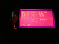
That's so valuable information! Is it just a coincidence that my print time is approximately 3.5 in f-stops? :D

That page in the link is pretty well written. Just the pages I'm after. Examples of values and practical tips without too much theory!
 
OP
OP
radiant

radiant

Member
Joined
Aug 18, 2019
Messages
2,135
Location
Europe
Format
Hybrid
Here is what my screen looks like now after one "scanning" of negative on enlarger:

upload_2019-8-19_22-44-31.png


On the right there is ratio, ISO(R) and wrongly calculated f-stop (calculated from ISO(R)..) so correct value should be f2.1 .. Bottom row shows the probe current luxes as "human" version and in actual value. And of course top right corner shows the multigrade number.

I got so drifted away with the multigrade calculation that I implemented it before the actual exposure time calculation.
 
Last edited:

gijsbert

Subscriber
Joined
Jun 17, 2014
Messages
214
Format
Medium Format
Very cool. I tried to 'build' one using a mobile phone light sensor but, as I feared, it wasn't sensitive enough to measure the highlights.

I don't know much about electronics: how far can the sensor be from the controller? I have a raspberrypi about one meter from my baseboard, would it possible to connect it with some electrical wire or would that change the measurements?

Thanks.
 
OP
OP
radiant

radiant

Member
Joined
Aug 18, 2019
Messages
2,135
Location
Europe
Format
Hybrid
Very cool. I tried to 'build' one using a mobile phone light sensor but, as I feared, it wasn't sensitive enough to measure the highlights.
I don't know much about electronics: how far can the sensor be from the controller? I have a raspberrypi about one meter from my baseboard, would it possible to connect it with some electrical wire or would that change the measurements?

The sensor uses I2C for data transfer and it starts to get tricky with distances of meter and over. It can work but it might be unreliable. For few meter transfers I would add Arduino Pro Mini, fetch the data with I2C from sensor and then print to serial port (and send it to rasperry pi for example). It's a bit stretch though.
 

koraks

Moderator
Moderator
Joined
Nov 29, 2018
Messages
22,898
Location
Europe
Format
Multi Format
Very cool indeed, nice project! Will you build an actual densitometer as well? It could be possible to add this as functionality with a bit of hardware and a few software mods. You're half way there already.

As to I2C distances: it may be possible to use longer wires if the I2C bus speed is throttled down significantly. Wires of a meter or so should be feasible, I guess. You may have to add some pull-up resistors to the wires.
 
OP
OP
radiant

radiant

Member
Joined
Aug 18, 2019
Messages
2,135
Location
Europe
Format
Hybrid
Very cool indeed, nice project! Will you build an actual densitometer as well? It could be possible to add this as functionality with a bit of hardware and a few software mods. You're half way there already.
As to I2C distances: it may be possible to use longer wires if the I2C bus speed is throttled down significantly. Wires of a meter or so should be feasible, I guess. You may have to add some pull-up resistors to the wires.

Thank you, it's actually your help that is making this happen. Again big thanks for helping out.

I haven't really seen need for densitometer - yet :smile: Also I have believed it needs some kind of optics to get more accurate spot readings? Or how the densitometer works / is used? I understand it can be used to measure how much film passes light through. If I place the lux sensor over the film it shows a some average from some small area of the film, I believe? Do I need densitometer? :smile:

Yes I2C can be extended with pull-up resistors but that can be a fiddle and it's easier if you measure the lines with oscilloscope. Of course one can just try different resistors and see what makes it work - but if you have no experience on electronics this I wouldn't go for this :smile: This more of a notice that one might get into troubles when extending I2C wires.
 

koraks

Moderator
Moderator
Joined
Nov 29, 2018
Messages
22,898
Location
Europe
Format
Multi Format
For a densitometry, you indeed need to measure a small spot. I suppose this could fairly simply be implemented using a led and a small collimator (basically a thick plate with a small aperture may do nicely) or even a low power laser diode. Do you need a densitometry? Probably not. But you can have one, isn't that enough reason? :wink: you don't need a lux meter after all! :wink:
 
OP
OP
radiant

radiant

Member
Joined
Aug 18, 2019
Messages
2,135
Location
Europe
Format
Hybrid
For a densitometry, you indeed need to measure a small spot. I suppose this could fairly simply be implemented using a led and a small collimator (basically a thick plate with a small aperture may do nicely) or even a low power laser diode. Do you need a densitometry? Probably not. But you can have one, isn't that enough reason? :wink: you don't need a lux meter after all! :wink:

Great idea to narrow measurement area. Density meter of course is a interesting device: what could I learn with this tool?

Maybe I don't need the lux meter but when it works it's a powerful time saver! :smile:
 

koraks

Moderator
Moderator
Joined
Nov 29, 2018
Messages
22,898
Location
Europe
Format
Multi Format
In general, densitometers are used to optimize the processes of negative exposure and development for whatever purpose. They're popular among zone system enthusiasts, but they can also be a great help in less strict/detailed approaches and to get a feeling for the kind of negatives you're producing and to what extent they lend themselves for whatever printing process you're using.
 

gijsbert

Subscriber
Joined
Jun 17, 2014
Messages
214
Format
Medium Format
Thank you, it's actually your help that is making this happen. Again big thanks for helping out.

I haven't really seen need for densitometer - yet :smile: Also I have believed it needs some kind of optics to get more accurate spot readings? Or how the densitometer works / is used? I understand it can be used to measure how much film passes light through. If I place the lux sensor over the film it shows a some average from some small area of the film, I believe? Do I need densitometer? :smile:

Yes I2C can be extended with pull-up resistors but that can be a fiddle and it's easier if you measure the lines with oscilloscope. Of course one can just try different resistors and see what makes it work - but if you have no experience on electronics this I wouldn't go for this :smile: This more of a notice that one might get into troubles when extending I2C wires.

Maybe I can get the raspberrypi closer to avoid lengthy wires and resistors. There is also some web posts about lowering the rate from 100k to 10k for improved cable distance without mention of pull-up resistors, wasn't necessarily people who have really done it.
Thanks for the info. This sounds like a fun project, I just wish I understand more about electronics!
 

ic-racer

Member
Joined
Feb 25, 2007
Messages
16,546
Location
USA
Format
Multi Format
While we are on the subject of a DIY darkroom light meter, I'd like to also ask a question. I don't own and I've never seen any of them. I suspect that they use a photodiode and there's one characteristic of the photodiodes that make things somewhat difficult. The angle at which light falls on the photodiode affects it's output. It progressively becomes lower as the angle becomes lower. The reading from the edges of the projected image may be lower than what it really is. So, do these meters have any kind of lens on top of the diode?

Moving the meter across the image will affect density measurements. The effect will differ with the type of enlarger, the fall-off of the enlarging lens and the Callier effect of the film being measured. To see the effects of these variables insert blank [or better, an evenly grey toned] film into the enlarger, take a reference reading at the middle of the projected image and with delta mode see how much the indicated density varies as the meter is moved to the corners and edges of the image. If measurement accuracy is critical then measurements should be made with the meter in a fixed position on the easel. The negative should be moved in the negative carrier to bring the desired spot over the meter.
Very complete enlarger metering instructions here, In fact, just buy the meter! http://www.darkroomautomation.com/support/eminstructionsj1.pdf
 
OP
OP
radiant

radiant

Member
Joined
Aug 18, 2019
Messages
2,135
Location
Europe
Format
Hybrid
Maybe I can get the raspberrypi closer to avoid lengthy wires and resistors. There is also some web posts about lowering the rate from 100k to 10k for improved cable distance without mention of pull-up resistors, wasn't necessarily people who have really done it.
Thanks for the info. This sounds like a fun project, I just wish I understand more about electronics!

Yes, go for it and try! It can work definitely, you can increase wire length in some amounts and see if the communication starts to fail and then you know the limit.

Electronics is not that hard, really. If you start with digital electronics there is no need to understand about currents or ohms (almost) at all. And it is a great way to slowly dive into analog electronics without first learning it all. I also suggest trying Arduino (for example get one Arduino Micro from ebay) https://www.theengineeringprojects.com/2018/09/introduction-to-arduino-micro.html - a lux difference measuring device (three leds, button and TSL2591) is not hard to build. Power it up from USB power bank and there you have your own darkroom meter :smile: Integrating LCDs isn't that hard either, there is plenty of instructions available what to connect to where. Of course there is some learning curve but I'm pretty sure everyone can get something working in few evenings if you want to.

Very complete enlarger metering instructions here, In fact, just buy the meter! http://www.darkroomautomation.com/support/eminstructionsj1.pdf

Although the document describes the device use, there is some really nice techniques buried under. Great find!
 

John51

Member
Joined
May 18, 2014
Messages
797
Format
35mm
Maybe I can get the raspberrypi closer to avoid lengthy wires and resistors. There is also some web posts about lowering the rate from 100k to 10k for improved cable distance without mention of pull-up resistors, wasn't necessarily people who have really done it.
Thanks for the info. This sounds like a fun project, I just wish I understand more about electronics!

If the raspberrypi can measure voltage, then an light dependent resistor can be be used as the sensor, same as in the older meters. It wont matter how long the wire is then.

V out from Pi > LDR > Pi input.
 
OP
OP
radiant

radiant

Member
Joined
Aug 18, 2019
Messages
2,135
Location
Europe
Format
Hybrid
If the raspberrypi can measure voltage, then an light dependent resistor can be be used as the sensor, same as in the older meters. It wont matter how long the wire is then.

V out from Pi > LDR > Pi input.

This comes down to raspi AD converter resolution and to sensitivity of the LDR. I tested TSL2561 sensor first (0.1 lux resolution) and found it too inaccurate for measuring the light coming from my enlarger. It could detect aperture changes but the changes in digital values started to lack accuracy (sorry I cannot remember what those were..) TSL2591 is marketed as 188 uLux and it is clearly more sensitive than 2561 what I have experienced. I have a feeling that 0.01 lux resolution is good to have.

Edit: I wrote in the first post "I get lux values ranging from 0.066 to 0.8 lux." which is still correct. So there is a some measured reference for this.
 

koraks

Moderator
Moderator
Joined
Nov 29, 2018
Messages
22,898
Location
Europe
Format
Multi Format
That's correct, getting the required sensitivity and resolution with an LDR and on board Adc will be much less trivial than it seems at first glance.
 

Anon Ymous

Member
Joined
Feb 7, 2008
Messages
3,661
Location
Greece
Format
35mm
IIRC, light dependant resistors don't have linear response to light intensity, making them even less suitable to this application. A photodiode is a better choice and some have their own amplifier. Texas Instruments has the OPT101 for instance.
 
OP
OP
radiant

radiant

Member
Joined
Aug 18, 2019
Messages
2,135
Location
Europe
Format
Hybrid
First tests with complete calculation features. Now the meter calculates contrast and exposure delta in f-stops. Dialed down the enlarger lens aperture and got close enough results so to confirm the calculation works correctly. Also tested column height, from 400mm -> 550mm I got 1.35 f-stop difference while luxes went from 0.1lux to 0.041 lux.

The UI is quite a mess and more like a debug screen but on right there is "base" exposure which can be adjusted - this is the value where the "fdiff" is compared. luxf is calculated f-stop from current measurement. So in this example I should add 1.09 f-stops to exposure time to get same shade/tone where as in "base" measurement.

The darkroomautomation pdf is full of good methods. I actually have seen that previously but I didn't understand a thing back then, maybe because I didn't understand the f-stop printing concept (thinking that it is sometime that I don't need..).

I have many times wanted some simple 10x15 prints from photos I'm probably never going to enlarge to larger sizes and this way it should be pretty easy. I start to believe that darkroom enlarger meter is not an option, it's a must :smile: If I couldn't build thing myself, I would definely buy darkroomautomation meter. However would I understand still how awesome this kind of device is? :smile:

.. writes a guy who hasn't even used this thing on actual printing ..
 

Attachments

  • 201908211412271056583084.jpg
    201908211412271056583084.jpg
    107.6 KB · Views: 115
Photrio.com contains affiliate links to products. We may receive a commission for purchases made through these links.
To read our full affiliate disclosure statement please click Here.

PHOTRIO PARTNERS EQUALLY FUNDING OUR COMMUNITY:


Ilford ADOX Freestyle Photographic Stearman Press Weldon Color Lab Blue Moon Camera & Machine
Top Bottom