Build a shutter tester for Focal Plane shutters - Cheap, Easy & it Works

Dog Opposites

A
Dog Opposites

  • 1
  • 1
  • 92
Acrobatics in the Vondelpark

A
Acrobatics in the Vondelpark

  • 6
  • 4
  • 167
Finn Slough Fishing Net

A
Finn Slough Fishing Net

  • 1
  • 0
  • 100
Dried roses

A
Dried roses

  • 13
  • 7
  • 190
Hot Rod

A
Hot Rod

  • 5
  • 0
  • 113

Recent Classifieds

Forum statistics

Threads
197,464
Messages
2,759,468
Members
99,513
Latest member
gtek-india
Recent bookmarks
0

ic-racer

Member
Joined
Feb 25, 2007
Messages
16,483
Location
USA
Format
Multi Format
Where were you looking, as a matter of interest? I’d really like 3.3v lasers with a narrower beam.

In terms of a narrower beam, make sure you get ones with the collimating lens. Some are sold without the lens, so the beam spread out more. If the ad indicates something like "good for laser pointer" then it should have the lens. If it indicates "beam spreads 10-15mm at 15meters" it probably does not have the lens.
 

Attachments

  • Screen Shot 2023-04-27 at 3.40.09 PM.png
    Screen Shot 2023-04-27 at 3.40.09 PM.png
    1 MB · Views: 78

Xylo

Member
Joined
Dec 6, 2008
Messages
405
Location
South of Montreal, Canada
Format
Multi Format
I’d really like 3.3v lasers with a narrower beam.

Maybe you could just mask out the diode with a pinhole (or even better a small tunnel).
Depending if there are any other components on the lasers, these are usually just a diode with some resistors. Running them at a lower power should simply reduce the light output. If not, just changing the resistor pack should fix things.

But I just checked and the esp32 does have a 5v pin.
If the NodeMCU is chosen instead, it's possible to get the 5v directly out of the USB port.

As for me, I'm thinking it would be interesting to convert the project from a 2 laser design to a 4 laser one so that vertical shutters can also be tested. Though that would take a bit of re-packaging of the project.
 

ic-racer

Member
Joined
Feb 25, 2007
Messages
16,483
Location
USA
Format
Multi Format
Maybe you could just mask out the diode with a pinhole (or even better a small tunnel).
Depending if there are any other components on the lasers, these are usually just a diode with some resistors. Running them at a lower power should simply reduce the light output. If not, just changing the resistor pack should fix things.

But I just checked and the esp32 does have a 5v pin.
If the NodeMCU is chosen instead, it's possible to get the 5v directly out of the USB port.

As for me, I'm thinking it would be interesting to convert the project from a 2 laser design to a 4 laser one so that vertical shutters can also be tested. Though that would take a bit of re-packaging of the project.

I'm placing the two lasers at the diagonal of the film format.
 
OP
OP

Niglyn

Member
Joined
Feb 26, 2022
Messages
403
Location
Surrey, UK
Format
Analog
Is either one of these boards ok?

I'm trying to buy locally (hate waiting for things from aliexpress) and I have absolutely no idea what I'm doing :D
I've built a shutter tester before (single LED, arduino) but in a 'monkey sees, monkey does' fashion so I'd rather ask a stupid question than see the magic smoke escape my components.

Thank you!

Hi,
Get the second one, it is ESP32. The first board does not have the correct processor.

The board only has 30 pins, the one I used has 38, but that is no issue.
I used the 38 pin board as it goes nicely with the 38 pin screw-terminal breakout board.

The lasers and rx modules work fine connected to the 3.3v pin, as shown in my diagram.

Now, a note on the 5V/3.3v issue.
The board has a 5v to 3.3v regulator built in, so it takes the 5v from the USB connector and converts it to 3.3v to run the microcontroller. It also supplies 3.3v to one of the pins, so things like the lasers can be connected to it.
It also routes the USB 5v to the 5Vin pin, so 5v is available for use as well.

The input pins of the ESP32 are '5v tolerant' which means you can put 5v onto an input pin without damage to the microcontroller. what you cannot do is put 5v into the power input pin of the ESP32.
 
Last edited:
OP
OP

Niglyn

Member
Joined
Feb 26, 2022
Messages
403
Location
Surrey, UK
Format
Analog
Hi guys, reading though the latest posts,
Yes, a laser needs the correct voltage to laze, else it is just an LED. I can report the ones I have specified, the standard Arduino modules certainly do laze when running on 3.3v and work perfectly. There is no reason you could not connect them to the 5Vin pin if you prefer. (This pin gives 5V out, when powered from the USB socket)

Similarly the rx modules work fine on 3.3v. the LED is dimmer.

The modules contain 5mw lasers. It is possible to purchase them without the development board, which may make mounting them easier, if you intend to mount them in a project box. Aliexpress do some with a choice of dot, line or cross. Have not tried them, but will order a few.

The device is accurate enough as is. However, an upgrade would be to mount both lasers & rx in project boxes. This would stop them being knocked out of alignment. The rx, as mentioned could be mounted on little tubes inside the box, to space them away from the 1mm holes. The laser barrels are easier, just drill barrel diameter holes in a piece of ply, at 30 0r 20mm spacing and mount that into the box.

The spacing of the lasers will be 30mm for horizontal, or 20mm for vertical shutters.
If mounting in project boxes, it would be easy to put two sets of lasers & rx in there, so it would measure either.
I will add some code to allow this.
 

koraks

Moderator
Moderator
Joined
Nov 29, 2018
Messages
20,654
Location
Europe
Format
Multi Format
The input pins of the ESP32 are '5v tolerant' which means you can put 5v onto an input pin without damage to the microcontroller.

I assume you're aware of the long-standing debate on this, but I'd like to make a disclaimer why I think it's bad practice to design a circuit that exposes the ESP32 to 5V logic levels.

Apparently the ESP32 was at least originally designed to be 5V logic level safe (while running at its maximum power supply voltage of 3.3V), and this was mentioned in the early datasheets. This mention disappeared from the documentation, someone reached out to Espressif who stated that the chips were still 5V tolerant at their GPIO's, but this information was removed from the datasheet because it was confusing.

Now, keep in mind that these chips can go through several die versions without explicit notice to the outside world. Lacking current official information (mention in the datasheet) that 5V compatibility is maintained, it's no more than an educated guess that it's still true for current and future generations of this chip.

This means that if you build a circuit today or tomorrow with an ESP32 and 5V logic levels, there's inherent uncertainty whether the ESP32 will survive this. It may very well - until proven otherwise. It's just kinda disappointing to be the guy/gal who happens to be among the first generation who unwittingly prove otherwise...

Fortunately, there is never a solid reason to expose a 3.3V processor to 5V logic levels - it's relatively easy to do it properly. As for instance in this case, where the peripherals work just fine on 3.3V to begin with.

TL;DR: my advice is to NOT mix 3.3V and 5V logic levels unless you're damn sure about what you're doing.
 

snusmumriken

Subscriber
Joined
Jul 22, 2021
Messages
2,354
Location
Salisbury, UK
Format
35mm
The spacing of the lasers will be 30mm for horizontal, or 20mm for vertical shutters.
If mounting in project boxes, it would be easy to put two sets of lasers & rx in there, so it would measure either.

I think space would make this difficult or impossible with the lasers mounted on their boards. As @Xylo suggests, some re-packaging would probably be required.
 
OP
OP

Niglyn

Member
Joined
Feb 26, 2022
Messages
403
Location
Surrey, UK
Format
Analog
I think space would make this difficult or impossible with the lasers mounted on their boards. As @Xylo suggests, some re-packaging would probably be required.

Yes agree. Whilst he modules make it easy for tinkers to hook up using dupont wires. If they were to be mounted into a project box, using the lasers with tails rather than the ones on the module would be far easier.

Due to the current lack of a workshop, I can't do anything at the moment. However, I would get a bit of 6mm ply and cut to fit in a project box, size of approx. 80 x 45mm. Then from centre, drill two holes at the 3 & 9 o'clock position at 32mm centre and two holes at 12 and 6 o'clock at 20mm centre. The laser barrels can then be mounted in the holes.

Do the same with the rx sensors. Dispensing with the module board is a little trickier here as a pullup resister and capacitor needs to be added to each sensor. It would be possible to use the internal pullup and dispense with the resister, but then it complicates things with different versions of code.

The project boxes would need to be accurately aligned, a similar holder to my patent pending wooden one would be fine.

A little light reading:-
 
OP
OP

Niglyn

Member
Joined
Feb 26, 2022
Messages
403
Location
Surrey, UK
Format
Analog
I assume you're aware of the long-standing debate on this, but I'd like to make a disclaimer why I think it's bad practice to design a circuit that exposes the ESP32 to 5V logic levels.

- yes I am

Fortunately, there is never a solid reason to expose a 3.3V processor to 5V logic levels - it's relatively easy to do it properly. As for instance in this case, where the peripherals work just fine on 3.3V to begin with.

TL;DR: my advice is to NOT mix 3.3V and 5V logic levels unless you're damn sure about what you're doing.
Totally agree. Different voltages are bound to cause something to go pop, especially when playing with development and breadboards. Fortunately in this case, the laser & rx modules work quite happily at 3.3 volts.
 

ic-racer

Member
Joined
Feb 25, 2007
Messages
16,483
Location
USA
Format
Multi Format
I'd think the sensors from the "Film Camera Tester" on GitHub could be used for this project.
In this picture, I have not made the holes yet, but I marked them in pencil.
sensor 1.jpeg
 

Xylo

Member
Joined
Dec 6, 2008
Messages
405
Location
South of Montreal, Canada
Format
Multi Format
I'm placing the two lasers at the diagonal of the film format.
That's a fantastic idea! A but like those lovely Yashica focus prisms.
The project boxes would need to be accurately aligned, a similar holder to my patent pending wooden one would be fine.
The best way to keep them aligned would be to mount both the transmitter and receiver on the end of a horseshoe shaped frame. Then you move the frame to change the gate size without affecting the alignment.
 

alinCiortea

Member
Joined
Jan 1, 2008
Messages
74
Location
Romania
Format
Multi Format
Thank you for your replies regarding the board choice. I couldn't find an breakout board for the ESP32 but if I get the 30 pin one I could use the 30 pin breakout board for the nano, right?

Anyway, this is work in progress with lots of mods on the horizon (film rails cutouts, overall size, sensor position for the receivers etc). Even at this size the lasers fit (the box is too shallow for the moment to accommodate the entire boards of the lasers). The receivers are a different story. I could either do a larger box or somehow solder jumper wires from the pins of the receivers to the their boards). The biggest challenge so far is getting them aligned while accommodating various cameras. Xylo's horseshoe idea is actually great (I was thinking something similar but like an arch above the camera - sometimes my brain goes into limp mode :D) and a series of lego style pieces could be designed, or just a piece of wood to keep them in position.

As soon as I reach a working design I'll post it here for everybody to print. I could also post the source files (freeCAD) for individual mods.

IMG_20230429_210225.jpg IMG_20230429_210254.jpg IMG_20230429_210324.jpg IMG_20230429_210513.jpg IMG_20230429_210446.jpg
 
OP
OP

Niglyn

Member
Joined
Feb 26, 2022
Messages
403
Location
Surrey, UK
Format
Analog
Thank you for your replies regarding the board choice. I couldn't find an breakout board for the ESP32 but if I get the 30 pin one I could use the 30 pin breakout board for the nano, right?

Nano breakout board will not work for the ESP32.

There are various breakout boards for the ESP32, I picked the one with screw terminals as it has less risk of the dupont wires coming out.
You can use the 38 pin breakout board, but the legend will not be correct.

Good work with the 3d printing. Hopefully somebody in the UK will offer to print me a set (hint hint) in return for my code.

Regarding the lasers, why don't you just buy the lasers with wires rather than the ones mounted on the module?
You could un-solder the lasers you have.

For the receivers, the could be taken out of the module and hot-glued into the box. It would be easy to solder a 0.1uf capacitor across the outer legs and a 10k resister (try a 1206 surface mount one) between the voltage in leg and the centre leg.

I would consider reversing the lasers and sensors, so the sensors fit into the camera back.

As for alignment, I would mount the two boxes on a jig, similar to my wooden version. They would then be permanently aligned.

The camera would then have shims under it, to lift to the correct height.

Carry on the good work :surprised:)
 

Xylo

Member
Joined
Dec 6, 2008
Messages
405
Location
South of Montreal, Canada
Format
Multi Format
I would consider reversing the lasers and sensors, so the sensors fit into the camera back.
The main reason why I'm not sure it's such a great idea is that the lasers will be pointing directly in the prism. Then you get the laser hitting the exposure meter and everything that's behind. Also, the mirror housing is not always the same size as the film gate.

Another way to get things aligned would be to have multiple custom lens caps with sensor attachment points on them. But I feel that is cumbersome when compared to a set of simple U shaped brackets.

As for adjusting the height, a series of differently sized blocks, a bit like the 123 machinist blocks, would do the trick.
Or to be really fancy a type of scissor lift... there might be some already designed on Thingiverse.
 

alinCiortea

Member
Joined
Jan 1, 2008
Messages
74
Location
Romania
Format
Multi Format
I know the receivers should be at the film gate (I don't know why, though :smile:) ), but I thought it would be easier to position the camera correctly if the lasers are behind it (I always see where they are pointing). More so for me as I'm going through my "fixing Leica III clones" phase. Being stripped out of the body shell the shutter won't allow for a fixed position while testing.

For the time being I went the 'just make it work' route and built a tester rig from a piece of wood, but took a lot of time for cable management (I'm quite proud of the result). I've uploaded the laser test file and the sensors are working fine.
Unfortunately the LCD seems dead. The wiring is ok, all libraries and drivers seem ok but it's not turning on and it's not seen by the arduino either. Any other method of determining if it's dead or just miswired?

Also, the serial monitor returns some gibberish characters (last attached image) when trying to test a camera. Obviously I'm totally stuck and have no idea where to look for errors...
Any help will make a huge difference :smile:


IMG_20230430_193659.jpg IMG_20230430_193708.jpg IMG_20230430_193716.jpg IMG_20230430_193727.jpg IMG_20230430_193819.jpg IMG_20230430_202011.jpg IMG_20230430_201959.jpg
 

Xylo

Member
Joined
Dec 6, 2008
Messages
405
Location
South of Montreal, Canada
Format
Multi Format
the serial monitor returns some gibberish characters (last attached image) when trying to test a camera.
That's because you most likely have the connection set at the wrong baud rate.

I know that testing Leicas that don't have the flip-up door like the M series is a definite pain.
Maybe the casing from a junk Zorki would fit them? If so you could just cut-out a door in it for the sensors...
Or make a replica casing just for testing using some plastic or galvanized metal.
 

alinCiortea

Member
Joined
Jan 1, 2008
Messages
74
Location
Romania
Format
Multi Format
PS: shouldn't the LCD light up, even I'd reading nothing, if only VCC and GND are connected? (there's no brightness pot on mine)
 

alinCiortea

Member
Joined
Jan 1, 2008
Messages
74
Location
Romania
Format
Multi Format
That's because you most likely have the connection set at the wrong baud rate.

I know that testing Leicas that don't have the flip-up door like the M series is a definite pain.
Maybe the casing from a junk Zorki would fit them? If so you could just cut-out a door in it for the sensors...
Or make a replica casing just for testing using some plastic or galvanized metal.

I gotta say, you have some intense ideas :smile:)
I don't have the skills and tools to try such methods.
What's the correct baud rate?
 

Xylo

Member
Joined
Dec 6, 2008
Messages
405
Location
South of Montreal, Canada
Format
Multi Format
Depends on the board itself and the code.
The default on the nano is 9600 bauds. But in the code it is set much higher
Serial.begin(115200);
so setting it at 115200 bauds, 8 data bits, no parity, 1 stop bit should make the serial console work.
 

alinCiortea

Member
Joined
Jan 1, 2008
Messages
74
Location
Romania
Format
Multi Format
yep. That did the trick.

One more question: if laser 1 is at the right of the film gate and laser 2 is at the left, how should I interpret the results? I mean if curtain travel time is faster on laser 1, which curtain is that pointing to?

PARAMETER LASER2 LASER1

Shutter Speed Seconds 0.008 0.014
Shutter Speed Fraction 1/126 1/72

Curtain Travel MicroS 17596 23628
Curtain Travel MilliS 17 23
 

alinCiortea

Member
Joined
Jan 1, 2008
Messages
74
Location
Romania
Format
Multi Format
Don't mind me... in my head I was still interpreting a 3 sensor tester (with the middle sensor reading the compound exposure).
If the tester reads 'laser 1 seen' when the opening curtain begins the travel, it will use 'laser 2 seen' to calculate curtain travel and 'laser 1 blocked' to calculate exposure time. So, for consistency, I assume laser 1, as long as it's positioned on the right side of the film gate (as seen from behind) means opening or first curtain.

Am I correct?
 

Xylo

Member
Joined
Dec 6, 2008
Messages
405
Location
South of Montreal, Canada
Format
Multi Format
Depending on the direction of travel and the shutter speed, this can be interpreted differently.
If the speed tested is below the flash sync speed, the entire frame will be open for part of the exposure.
If, lets say, the shutter travels from right to left like on my FED; and that laser 1 is on the right, it will record the acceleration phase of the shutter. If laser 2 is in the middle, it will indicate the average travel speed.
The difference between the open and blocked state will be the actual shutter speed.
The travel speed will be how long it takes the shutter to cross the frame.

Sometimes, if there are jumps in the travel speed, it could be grime in the tracks or on the curtain gears.
Now, the first trap will always be slower than the second trap as the shutter is gaining speed at that point.
It's a matter of figuring out by how much and if it's going to change anything on the film.
And also, it will tell you how far away you actually are from the selected speed.

So, if on your test you had selected 1/125th of a second, then it's pretty much right on the money for the center. The slow start can be attributed to tired springs.
But if you have selected 1/250th, then the camera really needs a CLA as it's running 1 stop too slow.
 

alinCiortea

Member
Joined
Jan 1, 2008
Messages
74
Location
Romania
Format
Multi Format
Wow! That's more than I bargained for...

First thing first... Camera repairing is a new hobby I discovered 5 months ago. So I'm still learning the ropes. For the time being I'm proud to say that I overhauled a Topcon Uni (the one with the Seikosha leaf shutter), a FED2 (it was a can of bits, pieces and screws) and two Zorki 4 (the complete process is here:


though I don't know who in the right mind would actually watch a 2h long timelapse).

I've stripped them down to the last screw, cleaned, polished and lubricated all moving parts but in the end I got stuck at adjusting the curtains (without a proper shutter tester). What I did was film in slow motion the shutter at a reasonable fast shutter speed (usually 1/125) with my phone (records 10 seconds long slow-motions at 960fps so plenty fast for eyeballing it), with a strong light behind and a piece of unexposed film stuck to the film gate. On the piece of film I drew vertical equidistant lines, so I could better assess the rate of travel. Then, when both curtains seemed to have the same speed, tested the speeds on my single LED tester and further adjust the tension. Then go back to the slow-motion and recheck the speeds. And so on.
Moreover, I tested both Zorkis with film and the frames came out evenly exposed.

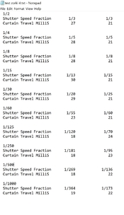
These are the results on the dual laser tester... I left only the relevant info (IMHO). The difference in curtain speeds makes no sense to me. Maybe I could actually miss it on the film test due to exposure latitude, scene photographed, angle of light etc, but wouldn't I see it on a slow motion?

The part that contradicts me is that testing my OM1, while top speeds are nowhere near what's on the dial, the curtain speeds are almost identical. All my electronically controlled cameras have vertical traveling shutters so I can't use them for cross-checking.

According to my understanding, the second curtain is too slow, right? So I could increase tension until capping occurs and then back up slightly.

All this effort towards the shutter tester was exactly for this: calibrating shutters after CLA/overhaul as good as I possibly can, given the aged springs and reasonable tolerances of these cameras.

Thank you, everybody, for putting up with my silly questions :smile:
 

Attachments

  • zorki test.jpg
    zorki test.jpg
    318.1 KB · Views: 66

alinCiortea

Member
Joined
Jan 1, 2008
Messages
74
Location
Romania
Format
Multi Format
My struggle understanding how to interpret the results continues.
I've attached an image with the results from the testers. I've also included two slow-motion videos at the same 1/125 shutter speed.
My interpretation is that the second curtain takes a lot more time to get to speed. That's why the travel time differs and the overall shutter speed gets faster as the measurement point is shifted to the left of the film gate. Yet, in practice, both curtains seem to travel with the same constant speed. The gap between curtains is also constant and consistent across the speeds range including 1/1000, also attached below.
I'm inclined to think that in use the camera should perform adequate for its age and intended purpose but it bugs me not having good values :smile:


Untitled.jpg
 
Photrio.com contains affiliate links to products. We may receive a commission for purchases made through these links.
To read our full affiliate disclosure statement please click Here.

PHOTRIO PARTNERS EQUALLY FUNDING OUR COMMUNITY:


Ilford ADOX Freestyle Photographic Stearman Press Weldon Color Lab Blue Moon Camera & Machine
Top Bottom