OP
OP
reneboehmer
Subscriber
Thank you for sharing this detailed and well thought out project.
Thank you!


Thank you for sharing this detailed and well thought out project.
I think the LCD would be great for it. Having seen ic-racer’s sensitometer shootout and seeing significant latent image degradation effects, I think marking timestamp is more critical than light source falling short of ideal.
A standalone edge stamper would be good too
You might remedy this by making the left and right walls out of mirrors, creating virtual LEDs to the left and right, without increasing the physical width of your box.I have slight falloff to the very left and right, because the leds are not longer than the illumianted surface.
You might remedy this by making the left and right walls out of mirrors, creating virtual LEDs to the left and right, without increasing the physical width of your box.
Another sensitometer I haven't seen mentioned was the Photex 2B by Condit Manuf. About the same size as the Speedmaster ones. Was incredibly repeatable. Sold for $ 250 40 years ago. Haven't seen any on the used market. Worth keeping an eye out for one. When I was working with a $ 250K MTL Star sensitometer I did a crossover with the Photex so I essentially had a super calibrated $ 250 unit.
Thanks for this image. Nice to see such things.FYI, if you had not seen it, the ESECO uses a system like this. Multiple downward pointing LED and some diffusion sheet over the lightbox. Also note the light sensors for ensuring repeatable illumination.
Also, perhaps the 41 step wedge might not be worth the extra effort for such a large illumination stage?
View attachment 420812
41 steps could be easily done by two different exposures through one 21 step scale (allow one overlapping step). Could even do shoulder, reversal and re-reversal studies by making several increasing exposures.

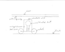
I also used a really cool table top model ( I don't remember the manufacturer) that looked like my crude drawing below. It was essentially a calibrated light bulb mounted to a chassis that was on wheels that rode back and forth on a track. The chassis was driven back and forth by a lead screw. An adjustable slit was mounted above the light source and traveled with the bulb chassis. A carbon step wedge was mounted above and a cover was above that. When actuated the bulb chassis would travel the length of the step wedge. Exposure time was adjuster by changing the slit width or speed of the lead screw.
I have seen this unit somewhere but couldn't remember the name. Thanks for the reminder. How did you guys perform calibration on your devices? I have ordered a Gossen Mavolux 5032B to measure surface illuminance of the glass.Yes. That's it.
| Photrio.com contains affiliate links to products. We may receive a commission for purchases made through these links. To read our full affiliate disclosure statement please click Here. |
PHOTRIO PARTNERS EQUALLY FUNDING OUR COMMUNITY:  |