-
Welcome to Photrio!Registration is fast and free. Join today to unlock search, see fewer ads, and access all forum features.Click here to sign up
You are using an out of date browser. It may not display this or other websites correctly.
You should upgrade or use an alternative browser.
You should upgrade or use an alternative browser.
Vivitar VI w/o power supply
-
A
- Thread starter VinceInMT
- Start date
Recent Classifieds
-
For Sale Nikon FE (blk) w/ 35-70 f/2.8 (Read)
- Started by Acere
-
For Sale FS: Horseman Long Loupe 6X
- Started by B.S.Kumar
-
For Sale FS: Linhof Master GTL / AMS 4x5 Camera
- Started by B.S.Kumar
-
For Sale Four H&Y Magnetic 4" Filter Holders and Four Cokin B&W Contrast Filters
- Started by Steve Goldstein
-
Sold Schneider Kreuznach Super-Angulon 165mm - 8x10
- Started by Guivd
Forum statistics
- Joined
- Feb 8, 2009
- Messages
- 1,293
- Format
- Large Format
Regarding posts #17, 20, and 22 and replies to them:
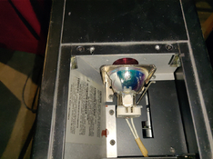
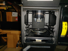
To give you meaningful answers, we need more-detailed information. Close-up photos of the open head showing the condenser configuration would be helpful.
On page 7 (at bottom right corner) of the manual, we see a paragraph with the bold blue heading:
“4. Enlarging Lamp Alignment.” This refers only to the standard light source. It has nothing to do with the Dichroic Light Source.
On the 7th page of the file (marked “5” in the lower right corner), we see the lower right photo of the open condenser housing. It shows a lone slide-in “Adjustable Condenser” (mounted in a metal plate) in the lower 35 mm position. That will narrow the beam of the condenser assembly to concentrate the light to just cover a 35 mm or smaller negative. The beam will be too small to properly cover a larger negative.
For larger negatives up to 6 x 6 cm, you must place the slide-in Adjustable Condenser in the upper slot so that the beam of light will be wide enough to fully cover the larger negative.
If you try to project a negative larger than 35 mm and your slide-in upper condenser is in the lower position, a circular dark band (or portion of a circle) such as you described could result. If so, simply move the upper condenser to the 6 x 6 cm position to see if it cures the problem.
You can also project an even wider beam for 6 x 7 cm negatives with the optional 6 x 7 cm condenser set. These are very hard to find now, as relatively few were sold when the machine was in production. Consequently, they are seldom seen on the used market now.
Last edited:
I see, this is a great setup!
Even for 35mm I'd try adjusting the condensors for 6x6 and see if that helps with more uniform
Even for 35mm I'd try adjusting the condensors for 6x6 and see if that helps with more uniform
A couple questions on the pictures. Are you sure the light pipe is installed correctly? Green circle.
Also, what is the object circled in red?
MISTAKEN: I thought these pictures were posted by hsvdg with the un-even exposure. But I was mistaken.
Ian-C, thank you for the answers.

Also, what is the object circled in red?
MISTAKEN: I thought these pictures were posted by hsvdg with the un-even exposure. But I was mistaken.
Ian-C, thank you for the answers.
Last edited:
- Joined
- Feb 8, 2009
- Messages
- 1,293
- Format
- Large Format
Regarding the photo of post #29:
The lever in the red circle is the lifting lever of the Condenser Canister. It raises and lowers the canister for loading and unloading the negative carrier. On page 4 of the manual, we read:
“6. Insert Negative Carrier
Swing lever on main condenser cluster to far right. Insert negative carrier (35mm or 6cm x 6cm) with locating ring facing down. Seat locating ring in negative carrier stage opening and swing lever to far left, holding negative carrier in position. (see photo “I”).”
http://www.jollinger.com/photo/cam-coll/manuals/enlargers/misc/VivitarVI_Manual.pdf
Last edited:
OK, I’m the OP reporting back in.
The power supply I needed for this enlarger, according to the specs for the dichroic version, needs to produce 18V, 4.3 amps. I dug around online and came up with one that does 18V at 10amps and bought it for a bit less that $24 US. It arrived and once I figured out which terminal was which, and switch it to 110 VAC from the 220 it came preset as, I attached a power cord and plugged it in. The DC voltage read 17.6 but I was able to adjust it to 18 with a trimmer pot it had.
Next I cut the plug that was on the cable from the enlarger. The bulb is a quartz halogen and is not polarity sensitive. I hooked that cable to the power supply, plugged the power supply in and no light. I pulled the bullb, checked with my ohm meter, and sure enough it was blown. I went online and found that these bulbs range in price from $11-28. I went with a GE bulb like the one that was in there and it was about $22 for the bulb, delivered. It arrived yesterday.
Today I installed the bulb and plugged in the power supply and there is light. I got out my extra timer, hooked it up and everything works as it should. BTW, the timer is switching the AC.
Now to pull the rest of the enlarger apart for a cleaning and try making my first print with It.
Success!
You'll have to mask that nasty green power LED on the supply.
Yep. I plan to put that supply in its own enclosure and mount it under the table.
I mounted the power supply for the Vivitar enlarger under the enlarger table. Easy with some linked-together zip ties. The green LED on the unit, which is only on when the enlarger bulb is, is pretty hidden down there but I think I’ll hang a piece of black mat board off the edge of the table just
 to be safe.
Simple solution! Weren't you tempted to mount it the other way, with the bare live connections towards the rear?
Considering how many of my projects require disassembly at some point, I figured I‘d leave myself easy access. From that end of the table there’s a wall about 16 inches away so it’s not mounted where I might likely encounter live wiring. Plus (it’s hard to see in the photo) there is a plastic cover over those cable connections.)
I'd put that in an enclosure. You can get an enclosure and IEC connector in AliExpress or Amazon for a few dollars.
Thanks. If I scrounge in my junk pile I probably have something like that. Since this is sort of a trial set up I wasn’t going to get that fancy yet. Plus, I’m the only one who is ever in the darkroom so I’m not concerned with a random hand reaching under the table. I’ve already gone through this house and torn out all the scary electrical that the previous owner had done and this set up is quite mild compared to what I’ve found.
I mounted the power supply for the Vivitar enlarger under the enlarger table. Easy with some linked-together zip ties. The green LED on the unit, which is only on when the enlarger bulb is, is pretty hidden down there but I think I’ll hang a piece of black mat board off the edge of the table just to be safe.
Well done!
That power supply looks like the ones used in 3D printers.
The green led can be quite powerful, making a enclosure (even with cardboard) will help (or you might cover the LED with electrical tape)
Have you had a chance to use it yet?
Yes, I did last night. I had a roll of FP4+ 125 in 120 that I’d shot on a quick motorcycle ride to Saskatchewan a few weeks ago and wanted to test developers first. I loaded the same film, in 35mm, in a canister and went out in my driveway (in sub-freezing temperature), metered with my Luna Pro, and shot the whole roll of about 18 frames at the same scene. I cut the film into 3 parts and developed them separately:
D-76 stock for 8.5 minutes, 68 degrees with agitation 5 seconds every 30
XTOL stock for 8 minutes, ditto
XTOL 1:1 for 10 minutes, ditto
Note: the D-76 is in a gallon jug, stock, and I’ve run about 22 rolls through it since I mixed it last January.( I know, I know.). The XTOL is freshly mixed.
I set up the enlarger for an 8x10 but printed 4x5 samples. I ran a test strip on a D-76 neg, picked a time (7.5 sec at f/5.6), and printed each of the strips the same. Ilford MGRC, glossy, no filtration.
They all looked pretty good. Here they are, left to right, D-76 stock, XTOL stock, XTOL 1:1.
I should mention that this is my first experience with XTOL. I ended up developing that roll of 120 in XTOL stock.
The enlarger is a dream to use and I’m looking forward to trying it with split-grade printing, something I was learning before I got sidetracked a few months ago. I was shuffling filters in my Beseler 23C and the color head on the Vivitar will make that much more manageable. I think that my Beseler 120 negative carriages might work in the Vivitar but I’ll need to make a lens board for my 80mm Schneider.
I didn’t add an enclosure to the power supply but did add a light baffle to deal with the green LED. I made it out of black mat board and it works fine.

Have you had a chance to use it yet?
Today I made an 8X10 print and am satisfied with its functionality although I haven’t tried the filters yet. This image is from a 35mm negative on Kentmere 100 that was developed in D-76 stock. I shot this about 2 years ago. Printed on Ilford MG Pearl.
NICE! congrats
Do you have an enlarger lightmeter (Ilford EM10 or similar)?
IN the book Way Beyond Mochrome, Ralph Lambrecht showed a way to determine exposure time and suggested filtration using one of those.
PS:
the graph is here in the WayBack Machine:
EM-10 Graph at the WaybackMachine
For the EM-10:
1. measure a highlight and calibrate aperture to read 90 on dial.
2. measure a shadow and read the gauge.
3. determine grade from graph using 1 and 2 above
I assume you can adapt it to other lightmeters
NICE! congrats
Do you have an enlarger lightmeter (Ilford EM10 or similar)?
IN the book Way Beyond Mochrome, Ralph Lambrecht showed a way to determine exposure time and suggested filtration using one of those….
Thanks for the info. No, I still do things the old way with test strips and, prior to this enlarger, I used filters in the filter drawer. Each filter had density number and I’d add them up and use the calculator wheel in the Kodak Color Dataguide to adjust exposure time.
| Photrio.com contains affiliate links to products. We may receive a commission for purchases made through these links. To read our full affiliate disclosure statement please click Here. |
PHOTRIO PARTNERS EQUALLY FUNDING OUR COMMUNITY:  |


