Using an LCD screen as a 'digital negative' in alt-process contact prints

Recent Classifieds

Forum statistics

Threads
199,146
Messages
2,786,998
Members
99,823
Latest member
nf56
Recent bookmarks
0

koraks

Moderator
Moderator
Joined
Nov 29, 2018
Messages
23,366
Location
Europe
Format
Multi Format
My first approach was to go buy a proper photodiode, then I thought, well I don't really need to compare to anyone, I just need this to work. So I thought about scratching the phosphor off. But when I realized just how hard that is, I just gave it a go without modifying the darn thing at all.

Just take a blue power LED with a decently-sized die. That's basically the same as your white LED with the phosphor removed (again, it's not a UV LED hiding underneath the phosphor).

But then I realized that any light from outside that makes the phosphor glow, will then emit some light of a different kind inwards to the diode.

Which for your measurement is basically irrelevant. The net efficiency is probably significantly higher with the phosphor removed. Keep in mind that a LED used as a photodiode is sensitive to wavelengths shorter than its peak wavelength when used as an emitter. So the blue diode inside a white LED is sensitive to UV, and in your use case, all the phosphor does is convert a little UV to green and red light. This is essentially lost to the sensor diode, which is blind to those longer wavelengths.
So in short, you're better off with a simple blue LED. Of course, white LEDs are plentiful, so there's a practical reason why you might prefer those; that's fair enough.

and you can add more diodes in series to get higher voltages that are less affected by the impedance
Or just build a simple transimpedance amplifier. Plenty of circuits all over the net.

there is modulation...not unexacted

Not sure what you mean here. Many light sources will indeed flicker at e.g. 50/60Hz grid frequency, or at a substantially higher frequency depending on how they're driven.
 

imgprojts

Member
Joined
May 24, 2024
Messages
104
Location
Seattle WA
Format
Multi Format
Just take a blue power LED with a decently-sized die. That's basically the same as your white LED with the phosphor removed (again, it's not a UV LED hiding underneath the phosphor).


Which for your measurement is basically irrelevant. The net efficiency is probably significantly higher with the phosphor removed. Keep in mind that a LED used as a photodiode is sensitive to wavelengths shorter than its peak wavelength when used as an emitter. So the blue diode inside a white LED is sensitive to UV, and in your use case, all the phosphor does is convert a little UV to green and red light. This is essentially lost to the sensor diode, which is blind to those longer wavelengths.
So in short, you're better off with a simple blue LED. Of course, white LEDs are plentiful, so there's a practical reason why you might prefer those; that's fair enough.


Or just build a simple transimpedance amplifier. Plenty of circuits all over the net.


Not sure what you mean here. Many light sources will indeed flicker at e.g. 50/60Hz grid frequency, or at a substantially higher frequency depending on how they're driven.

Alright, blue led it is...the modulation is interesting. I'll plug the LED on an oscilloscope and post a trace. There's a 60Hz signal in there but more stuff that I didn't dig into too much.
 

koraks

Moderator
Moderator
Joined
Nov 29, 2018
Messages
23,366
Location
Europe
Format
Multi Format
There's a 60Hz signal in there but more stuff that I didn't dig into too much.

There's likely loads of noise because it's a super high impedance circuit.

I tried this approach as a LED-as-a-sensor for a DIY UV dosimeter/integrator, but quite quickly decided it was so far inferior to a simple and cheap UV sensor that I abandoned it. The method I used did actually use an amplification circuit before feeding the signal into the A/D of a microcontroller.

As said, there are plenty of sensors that would be up to the task. One of the simplest ones is the ML8511 or GY8511, which appears on a number of DIY modules in the $5-$15 price range. The similarly-priced LTR-390 has an I2C interface and a slightly different spectral sensitivity. It also appears on several DIY-ready modules.

I'd seriously consider getting some kind of DIY UV module instead of mucking about with an LED, which is going to result in measurement problems one way or another.
 
OP
OP

AndrewBurns

Member
Joined
Jul 12, 2019
Messages
227
Location
Auckland, New Zealand
Format
Multi Format
I was just looking at UV sensors as I will need to include one in my UV projector system. I haven't bothered for my contact print setup because the amount of UV getting to the paper is quite consistent and so I've found just timing the exposure to be adequate. For the projector on the other hand, because I can change the enlargement and make prints of whatever size I want, the UV getting to the paper will be proportional to the degree of enlargement and can vary substantially. I could just measure the level of enlargement and have a calculation to work out exposure time, but it would be more accurate to have a UV sensor at the paper to integrate exposure.

The LTR-390 is really designed for peak sensitivity in shorter wavelengths and has almost no sensitivity in the 365 - 405nm range that most people will be printing in:
LTR-390UV.PNG


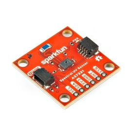
The AS7331 includes three different sensors, and the UVA one seems to have a more useful spectral response:
AS7331.PNG


It's not super cheap but not too expensive either. Sparkfun has a breakout board for the sensor, and it communicates over I2C as well which makes connecting it to a microcontroller or raspberry pi pretty easy.
 

koraks

Moderator
Moderator
Joined
Nov 29, 2018
Messages
23,366
Location
Europe
Format
Multi Format
There's quite a few UV sensors, some with I2C, some with a simple analog output. The AMS sensors (ASxxxx) are attractive; several of them will measure UV in various bands. The one you posted looks nice. They're all very well documented, which helps a lot. It takes a little getting used to working with them, but when you get the hang of it, you'll notice they all follow the same principle.
 
OP
OP

AndrewBurns

Member
Joined
Jul 12, 2019
Messages
227
Location
Auckland, New Zealand
Format
Multi Format
In order to take a break from experimenting with Zerochrome SbQ I had another crack at tiling together multiple contact print cyanotype exposures. I was never able to get the overlap between exposures working previously however this time I had a bit of a brainwave I wanted to try. Basically my trouble before was the screen density isn't linear to print density and so the overlap didn't result in the correct tone.

This time I realised that I could add exposure time rather than tone. To do this I basically played a very low frame-rate video on the LCD screen, where a black bar creeps up the screen in the overlapping region, so the overlap part of the print gets the correct exposure time from both contact prints. This actually worked surprisingly well, the overlap is seamless in terms of the detail of the picture, but there is a lighter band due to unevenness at the edges of my light source, not actually due to the overlap itself.


After about a dozen iterations I managed to largely reduce the visibility of this line by darkening that region in software:


Since then I've managed to make two quite successful prints, both of these are A3 sized and are made from two contact print exposures on a registration board with an overlap in the middle:


I've also had two failures where the overlap was visible, I think because the paper moved slightly between exposures. I think if I nail my technique for keeping the paper flat and immobile between exposures it could work pretty well, but ultimately I'm still keen on building a projector/enlarger to make larger prints as it should be a lot easier and more robust.
 
Joined
Aug 29, 2017
Messages
9,522
Location
New Jersey formerly NYC
Format
Multi Format
Bob, I'm old enough to have shot film as a child before digital really existed but young enough to have only ever taken photography seriously after digital had taken over, and so I'm only used to editing photos using digital tools. I've since discovered that I love taking photos using a large format camera and also the involvement of hand-made prints, but I can't give up the power and flexibility of digital photo editing (which also makes it easier to share my photos with people).

I think this kind of hybrid workflow is the best balance for me, I get the tactile engagement of shooting a scene with LF film, but then I scan and edit digitally. I do have a decent inkjet printer but I've always hated using it, so I'm excited to be working on a way of printing my digitized files in a way that is still genuinely involved and hand-made.

Like digital photo editing I think it also makes some techniques that would be possible but quite time consuming using more traditional methods easier and faster. For example if I wanted to make an alternative process print that required building up multiple different layers (e.g. multi-tone or colour prints) then I don't need to print out multiple digital negative transparencies or shoot multiple sheets of film, the screen can print as many 'negatives' as I send to it. I can also increase the tonal range of the screen by using software to automatically break an image up into different copies with slightly shifted exposure, which get automatically exposed one after the other onto the same print, kinda like how HDR photos work but in printing instead.

Then there are those of us who have no space for a darkroom. The hybrid approach is the main way we can operate. But that does allow sharing with others on smart TVs, monitors, YouTube, the web, email, messaging, etc. Of course, prints are really nice for family pictures where framed shots can be gifted and displayed in one's home. Outside processing sources have to be depended on.
 

Graham06

Member
Joined
Oct 31, 2006
Messages
139
Format
Medium Format
where a black bar creeps up the screen
What a good idea. I was thinking that your earlier failure was due to failure to account for gamma correction, but it is more than gamma, it's the full complicated response curve, and I don't understand clearly enough to suggest anything. It might not be too hard if you try calculate it on paper. It will be more fun for the center dot if you try do 4 images, but this avoids all that.

For registration, how about registration pins, and a piece of temporary registration tape with two carefully made strips with two holes (Dick Blick sells pins and plastic tabs cheaply.) You'll have to get the strips right once, but after that you just tape it to your paper with temporary tape. Maybe a whole registration board:

........_________......................................paper taped to board
....-||---------------||-...............................registration board with carefully placed registration holes
..------------------+---------------------...support board with registration pins
For your successful prints, what does the overlap area look like close-up? Can you see tiny double image pixels? If the pixel images are too pointy, maybe micro-misregistration could cause the visible stripe due to the gamma response weirdness:

....+--+--+....
....+--+--+....
vs
....+--+--+....
....-+--+--+.....
 
OP
OP

AndrewBurns

Member
Joined
Jul 12, 2019
Messages
227
Location
Auckland, New Zealand
Format
Multi Format
What a good idea. I was thinking that your earlier failure was due to failure to account for gamma correction, but it is more than gamma, it's the full complicated response curve, and I don't understand clearly enough to suggest anything. It might not be too hard if you try calculate it on paper. It will be more fun for the center dot if you try do 4 images, but this avoids all that.

For registration, how about registration pins, and a piece of temporary registration tape with two carefully made strips with two holes (Dick Blick sells pins and plastic tabs cheaply.) You'll have to get the strips right once, but after that you just tape it to your paper with temporary tape. Maybe a whole registration board:

........_________......................................paper taped to board
....-||---------------||-...............................registration board with carefully placed registration holes
..------------------+---------------------...support board with registration pins
For your successful prints, what does the overlap area look like close-up? Can you see tiny double image pixels? If the pixel images are too pointy, maybe micro-misregistration could cause the visible stripe due to the gamma response weirdness:

....+--+--+....
....+--+--+....
vs
....+--+--+....
....-+--+--+.....

Yeah I'm basically already doing this. It's a bit hard to see from this photo but on the bottom there's an acrylic board with registration pins that stick upwards, and on top my exposure unit (LCD facing down) has holes cut into it that match the registration pins. I can pick the exposure unit up and put it down on different sets of pins for doing exposures of different tiles.


I've tried laser-cutting registration holes in the paper (as you can see in one of the prints I shared) but I find that the holes aren't accurate enough and the paper can still move. A vacuum system to hold the paper down between exposures would be ideal. Another thing I've tried is taping the paper to a thin laser-cut plastic carrier board which then sits on the registration pins. This works fine (as you can see from the second print I shared above with no registration holes) however the way I tape the paper to the registration board seems to be important. I've tried wetting the paper and taping it down using gum tape so that when it dries and shrinks it pulls tight on the board, however the board is too flexible and the paper bends it into a taco shape. Then when I squash the taco flat with the exposure unit the tape can give way resulting in the paper shifting between exposures.

In the overlap area I can't really see any artefacting at all, at least when it works correctly. Maybe in some areas there's a slight blurriness compared to other parts of the print, but it's not noticeable even if you know exactly where to look and put your nose practically onto the print to see it.
 
Photrio.com contains affiliate links to products. We may receive a commission for purchases made through these links.
To read our full affiliate disclosure statement please click Here.

PHOTRIO PARTNERS EQUALLY FUNDING OUR COMMUNITY:


Ilford ADOX Freestyle Photographic Stearman Press Weldon Color Lab Blue Moon Camera & Machine
Top Bottom