aparat
Member
I would send it back because of the surface damage. They should have caught it before they shipped it.


Err, no. The DA meter's measurements of density include flare. The meter sees the same flare the paper sees. If you are doing by the book sensitometry this may be a problem unless you are measureing a negative of uniform density. If, however, you are doing work of a more practical nature then including enlarger flare can tell you more about the effect of changes to film exposure and development.Darkroom Automation’s meter ... introduces flare.
There is a sticky interminable thread on this subject https://www.photrio.com/forum/threads/factor-for-enlarger-head-height-adjustment.44339/... the relationship between enlarger height and print density ...
Err, no. The DA meter's measurements of density include flare. The meter sees the same flare the paper sees. If you are doing by the book sensitometry this may be a problem unless you are measureing a negative of uniform density. If, however, you are doing work of a more practical nature then including enlarger flare can tell you more about the effect of changes to film exposure and development.
Pays your money, takes your choice.
First, I calibrate a reference unit to the best of my ability. This begins with something I call "slope calibration", which is a process that uses a calibrated Stouffer T2120C (21-step wedge) to correct for any linearity issues with the sensor. The way the data is processed, minor step-to-step variations shouldn't cause a problem here. The result is basically coefficients for a correction polynomial.
After this, I perform normal calibration on the unit. That involves measuring an open aperture, and then measuring dead-center on patch 4 of a calibrated Stouffer T5100C (5-step wedge).
I recommend accepting Stouffer calibration readings as correct.
All three sets of measurements closely agree, as you see in posting #22. I can't imagine how I could have goofed all three.
When measuring a transmission step wedge, it is important to always measure from the same spot. One thing Stouffer does not do, is actually tell you which spot on their wedge the calibration values they provide were measured from. If you measure different points along the same patch, especially for the darker patches, you absolutely will see a difference. When I use mine, I always try to aim for measuring from dead center, and only from dead center.
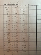
Here you can see Chuck_P’s readings with Dkoenig’s Dektronics Printalyzer Densitometer next to Stouffer calibrated readings.
Sorry Bill, but I don't see my P-D readings there on your hand written data, none of those match the P-D measurements that I posted earlier.....what am I missing?
From the posted graphs it seems the first-order differences are down to the spectrum of the light source used for measurement, any color filtration and the spectral response of the detector.
It’s a Marshall Studios densitometer.BTW, what visual densitometer are you using? I didn't know such a thing existed.
Mark

I sent the step wedge back yesterday. Stouffer was very apologetic as to the condition of the steps that had the spots on them. I talked to the lady who actually packaged the step wedge for mailing. She indicates with certainty, that the wedge did not look like that when inserted into the envelope and it had to have come from the ink on the calibration sheet packaged with the wedge.
They said this is the first time for an issue like this they have seen and are appreciative that ive brought it to their attention. They've been very positive and reassured me that they will take necessary precautions to fix that from happening again. I'm pleased with how they dealt with me in the process.
That still leaves the mystery of the Printalyzer Densitometer being significantly off when measuring a calibrated Stouffer wedge, considering that the device was calibrated with such a wedge.
Mark
There are a few questions.....
The question that I have is.......should the PD measurements have matched more closely, not suggesting perfectly, with Stouffer's readings on steps 12-21 of my stepwedge........as it did so nicely on steps 1-11.
Ex: Step 21 Stouffer's reading is 3.01, the PD reading is 2.94. I read the correct side and there were no smudges. Thanks.
1. Try this again, and see if you still see the same difference
2. If you do see the same difference, then try calibrating your PD against step 20 on your new Stouffer wedge instead of the strip it came with. After doing that, it'll most likely line up a lot better.
There are a few questions I have, which might help explain things:
- Which Stouffer wedge are you using, and how long ago did you buy it?
- Does the wedge have any smudges or signs of wear?
- Which direction is the emulsion facing when you measure it?
- Have you tried measuring the whole wedge? The numbers you've shown so far only seem to go about 2/3rds of the way into what I think the range of these things is. I'm curious as to whether the graph continues to follow the same straight lines with the same slope, or if it starts to curve at some point.
- Finally, what happens if you calibrate your unit against this Stouffer wedge instead of the calibration strip that came with the unit? (Pick a point around 2.9D, and call that "CAL-HI", when going through the process.)
Without a third or fourth reference to compare against, that's a hard one to answerMeasuring with emulsion up reduced the error. The right third of the graph disagrees by .04 and .05. Calibrating to my wedge reduced the error to about nothing, but the densitometer now substantially disagrees with the transmission reference. So which calibrated Stouffer wedge is correct?

I actually do. I just didn't underline or circle it, so its easy to miss. Right in the measurement instructions of the quick start guide:Here's a suggestion: In the materials accompanying the densitometer, have something prominently tell the user to measure with emulsion up. The natural action of people is to put the emulsion-side down; emulsion up never would have occurred to me.
| Photrio.com contains affiliate links to products. We may receive a commission for purchases made through these links. To read our full affiliate disclosure statement please click Here. |
PHOTRIO PARTNERS EQUALLY FUNDING OUR COMMUNITY:  |