-
Welcome to Photrio!Registration is fast and free. Join today to unlock search, see fewer ads, and access all forum features.Click here to sign up
You are using an out of date browser. It may not display this or other websites correctly.
You should upgrade or use an alternative browser.
You should upgrade or use an alternative browser.
Strange Nikon Coolscan LS-8000 color noise
-
H
- Thread starter tony25
- Start date


Recent Classifieds
-
For Sale Jobo CPE 2 Plus with Lift, - Tanks, Reels, accessories
- Started by nbagno
-
For Sale Multiple Large Format Lenses for sale
- Started by nbagno
-
For Sale Canon 2X EF Telextender
- Started by davela
-
For Sale Olympus OM 24mm F2.8 Lens Hood
- Started by davela
-
For Sale Original Rolleiflex SL35, SL35M, and Contax G2 Manuals
- Started by davela
Forum statistics
BMbikerider
Member
I cannot see a pattern just a mass of basically out of focus or over enlarged reddish imagery. Why not post a normal sized image where it is not over enlarged. blurred, and let us decide.
It looks to me very much like a solution looking for a problem. In other words we need a bit of lateral thinking for once
It looks to me very much like a solution looking for a problem. In other words we need a bit of lateral thinking for once
cramej
Member
- Joined
- Dec 29, 2009
- Messages
- 1,235
- Format
- Multi Format
I cannot see a pattern just a mass of basically out of focus or over enlarged reddish imagery. Why not post a normal sized image where it is not over enlarged. blurred, and let us decide.
It looks to me very much like a solution looking for a problem. In other words we need a bit of lateral thinking for once
I cannot see a pattern just a mass of basically out of focus or over enlarged reddish imagery
The pattern is very obvious in the examples in the first post and also in #14. I'm not sure why you can't see it; it's clear as day to me.
BMbikerider
Member
Do you mean the brown pattern around the edges? or on the red part of the image, if so you did not make it clear Which is a good reason to show the full frame not just a minute part of it? No one can make a judgement of a problem without having the full story, so I repeat show the full picture
No one can make a judgement of a problem without having the full story
No, but it seems most of us are doing OK in terms of recognizing the problem and its impact.
I agree that a full-scale image would give some context, but it wouldn't make troubleshooting any easier.
I also agree that some people would find this problem perfectly acceptable as it mostly manifests itself in the deepest shadows of scanned slides. But if OP experiences it as a problem, I'm not sure if it's very helpful to try and deny their problem.
BMbikerider
Member
You could compare these hugely enlarged sections with what looks like a finely machined piece of hard steel such as that used on a vehicle's crankshaft. I may look perfect. It may feel perfect. It it's natural size it may have what looks almost like a mirror finish, but enlarge it 100 or 200% or more it will appear be far from being perfect, in fact it will look like a relief map of the Himalayas!
There is a fine line between being perfect and what looks perfect and what is perfect enough to work under normal circumstances. In real life you cannot have perfection all the time if ever given what you suggest you would accept
If the originator of this perceived 'problem' were to do as I suggest and let us see the area of the 'problem' in a natural sized picture or a section of the same, for most people the image it may seem perfectly normal and 100% usable. Ask yourself, do you want to get your worry beads out every time there is what you consider to be a problem turning what is a really pleasant hobby into a source of angst where the fun goes out of it. Sorry that is not my scene.
I would suppose that anyone using a Nikon 8000 is not looking for ’good enough’ quality.
It’s like SD and HD. Without comparison, SD is fine, but put it beside an HD picture and you will see the difference. I can see the difference between the flawed scans from the Nikon and say some scans from a Plustek when zoomed out, not zoomed in.
It’s like SD and HD. Without comparison, SD is fine, but put it beside an HD picture and you will see the difference. I can see the difference between the flawed scans from the Nikon and say some scans from a Plustek when zoomed out, not zoomed in.
The problem is visible to my monitor (I have large monitor) when viewing full screen, sometime cropped, which is not usable for me. I shared these scanned images with other people, who sometime doesn't care, sometime care. My original intention is also to make sure that this scanner does not have any defect which it seems to have comparing to normal scanner.
tomro hope you can fix the problem. I think those caps should be available everywhere, or any repair shop should have them in stock. And I think yes, to koraks, they seems to be caps for A/D filter network.
tomro hope you can fix the problem. I think those caps should be available everywhere, or any repair shop should have them in stock. And I think yes, to koraks, they seems to be caps for A/D filter network.
I used the information from the PDF tony25 linked to.
Yes, I figured that, but I don't have Facebook, hence the question. In case the pdf has a photo included of the relevant PCB area, perhaps it's possible to include a screenshot of that page here in this thread.

Perfect!
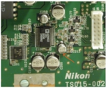
If that 10uF/16V electrolytic happens to be the problem, be sure to replace the others of the same value as well (e.g. the one right beneath the label 'C250'). Similar caps in similar positions from the same batch frequently have a similar life expectancy. Electrolytics don't have an infinite lifespan to begin with.
Sadly these caps are the more challenging ones to replace. There are two ways that come to mind:
1: With a regular soldering iron, get hold of some "litze"/desoldering braid, which is a copper mesh that will wick up solder. Fold a bit of the braid in an angle, press that against one of the contacts of the capacitor, then hold your soldering iron against it until most/all of the solder is wicked into the braid. While doing this, you can try to push the body of the cap away from the contact that you're sucking dry to see if it will lift off the PCB. Then do the same for the opposite contact. Temperature setting on the soldering iron will depend; this is likely already done with lead-free solder, so temperature will need to be fairly high. I generally set it to over 300C for a task like this, but you'll have to experiment. It helps to apply some flux to the contact before you start wicking up the solder, so buy some of that too. Any flux will do. A small to mdeium-sized chiseled soldering tip will work best for this.
2: If you have (or are willing to purchase) a hot air rework soldering station, just set it to a conveniently high temperature (350-400C for this job sounds like a decent starting point), with a broad aperture bit and high airflow. See if you can heat the entire thing in one go and try to pick it up with a pair of tweezers. Once the contacts are hot enough, the cap should lift right off the PCB without any effort. Make sure to blast the hot air away from the AD9822 chip.
Re-soldering the electrolytic cap is actually easier than removing it. With a normal soldering iron (option 1), I'd suggest melting some soldering tin onto both pads first so you have a nice bead. I prefer a leaded type of 60/40 or thereabouts, which will work just fine here, but manufacturers aren't allowed to use it as per RoHS. Apply some flux, then hold the capacitor to the pads and solder the contacts one by one, while pressing the capacitor down towards the PCB so that its contacts are ensured to be dipped into the tin puddle you made their. Observe proper polarity; the black wedge on the top of the electrolytic capacitor should be on the same side as the original one you remove. Mounting the new one in the wrong orientation will likely cause fireworks (the new cap will pop/explode) and possible damage to other components.
With a hot air gun, re-soldering the part can be done in a similar way; first wet the contact with a nice quantity of tin, apply some flux, press down the part with tweezers and heat the contacts until the capacitor 'melts' into place. But I prefer r(e)soldering these caps with a regular iron and a decently fine tip.
If replacing the 10uF/16V electrolytic capacitor helps anything, I'd also suggest replacing the bigger 100uF/6V caps. For instance C198 and C200 by the looks of it provide filtering for the analog 5V supply of the AD9822 and their performance is absolutely critical for a clean signal (the same is true for the smaller C196 discussed below).
See if replacing that electrolytic (and similar ones elsewhere in the device; see earlier remark) solves the problem. I have a feeling it might not, but who knows. If it doesn't help, I'd be tempted to also replace the smaller 0.1uF decoupling capacitors. These are the tiny tan-colored boxes. In particular you would want to replace the three little caps near the label 'C213', the single one just below the AD9822 labeled 'C196' as well as its sibling immediately above the AD9822 (to the right of the U117 label, between the 10uF/16V electrolytic and the AD9822 chip). Finally, C197 (to the left of the AD9822) should be replaced if you're going to do the all of the small decoupling caps.
Capacitor C201 of a similar function as the ones mentioned above is far less critical and unlikely to present a problem.
For the smaller capacitors (the tan ones), removal is relatively easy. With a regular soldering iron, take a decently large chiseled tip, set temperature to 300C or so and hold the tip against the length of the capacitor so that it touches both contacts. You may want to add some more tin to each of the contacts so that there's more surface area for the soldering iron to work with. Heat up the part and lift it off with tweezers. Shouldn't take more than a few seconds to get this done. Don't worry about destroying the part if you're going to replace it anyway. I often find the contacts dislodge or the body of the cap fractures a bit if force is applied; no worries. Just keep the replacement in one part (which is easy enough)!
With hot air, even easier: heat up, lift off with tweezers, done.
Resoldering with a regular iron and fine tip: wet one of the contacts with a little bead of tin. Press the part against the contacts, then tack the part into place by melting the bead of tin you've just deposited. The cap will now remain in place and you can solder the other contact by applying some tin to it.
With a hot air gun: apply some tin to both contacts, stick the capacitor to the contacts using some flux (or hold it with a tweezer), apply hot air until tin melts and the cap will 'magically' slide into place.
Don't even think of undertaking this if you do not have a soldering iron that with temperature control or a hot-air smd rework soldering station. Devices like soldering irons without temperature control, hot-air guns for automotive or general purpose use, 'soldering guns' used for plumbing or miniature gas flame soldering devices are NOT appropriate for this work.
Without the right tools this job WILL turn into a nightmare, whereas with the proper tools, it takes a few minutes and the result will be clean.
Good luck and let me know if you have any questions.
PS: there are millions of videos on YouTube about soldering SMD parts. Be sure to have a look at some. Some will do it the same way I described above, some will be subtly different. There are many ways; the above is what works for me.
The three small caps to the center right of the AD9822 are the input capacitors between the AD9822 and the actual CCD. I don't expect them to be faulty; the problems would look different and be far worse. When doing work around the IC, make sure to not damage these little capacitors and also not to overheat them, as this may degrade their performance.
Removing the small tan caps is similar to the electrolytics. It's easy with a hot air station, where you just heat up the entire part and pick it up with tweezers.
PS: if you have a working knowledge of electronics, I'd recommend studying the datasheet of the AD9822 chip which you'll find here: https://www.analog.com/media/en/technical-documentation/data-sheets/ad9822.pdf
Especially the application circuit on page 17 is relevant as you'll be doing work that relates to the components listed on it. It looks like Nikon's implementation follows these instructions closely (as it should!)

You can do it 
Perhaps practice first on a piece of e-waste!
I get most of this kind of equipment off of aliexpress to be honest. If you search for "soldering station" you'll find several suitable products.
If you want to buy in the west, get an entry-level Weller station with temperature control. You can't go wrong on those.
If you're hesitant about doing this yourself, feel free to pm (this is not a commercial offer!)
Paul Ozzello
Member
I did 8x sampling and it seems to be more obvious:
View attachment 321400
Are you using the glass holder? Could that be the pattern from the anti Newton glass ?
I ask because I get a similar pattern with mine on a 9000 - which disappears if I fluid mount.
Last edited:
Are you using the glass holder? Could that be the pattern from the anti Newton glass ?
I ask because I get a similar pattern with mine on a 9000 - which disappears if I fluid mount.
Definitely not. I get in on 35mm and rollfilm. All scanned without the glass holder
Paul Ozzello
Member
Definitely not. I get in on 35mm and rollfilm. All scanned without the glass holder
I had that exact same pattern on mine but I don’t know how I made it disappear. I did hook it up to a Back-UPS around the same time
| Photrio.com contains affiliate links to products. We may receive a commission for purchases made through these links. To read our full affiliate disclosure statement please click Here. |
PHOTRIO PARTNERS EQUALLY FUNDING OUR COMMUNITY:  |