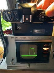
Shutter Speed Testing Focal Plane Shutters

Frank Dean,  Blacksmith

A
Frank Dean, Blacksmith

  • 8
  • 5
  • 73
Woman wearing shades.

Woman wearing shades.

  • 1
  • 1
  • 80
Curved Wall

A
Curved Wall

  • 6
  • 0
  • 92
Crossing beams

A
Crossing beams

  • 10
  • 1
  • 115
Shadow 2

A
Shadow 2

  • 5
  • 1
  • 86

Recent Classifieds

Forum statistics

Threads
198,842
Messages
2,781,733
Members
99,725
Latest member
saint_otrott
Recent bookmarks
0

ic-racer

Member
Joined
Feb 25, 2007
Messages
16,546
Location
USA
Format
Multi Format
I just finished evaluating some focal plane shutters and wanted to share the information as I found very little on this topic from the internet.

Before building the tester, one needs to know which information is needed. For a focal plane shutter, the fast speeds need special consideration, seeing as the mirror is up for a 1/60 (or higher) during the entire exposure, even though each individual portion of the film only receives light for example 1/1000 of a second.

To measure this one would need a theoretic point source from which the time the opening curtain passes to the time the closing curtain passes could be measured.

Then, to ensure evenness across the film plane, this measurement needs to be carried out near the opening side of the film gate and also near the closing side and in the middle too.

The design of many focal plane shutters (the one's I'm currently working on) fix the curtain velocity and mechanically release the closing curtain at mathematical 1/2s of the shutter gate. For example

Second Curtain Release:
1/60 = 36mm (full gate distance)
1/125 = 18mm (half gate distance)
1/250 = 9mm (1/4 gate distance)
1/500 = 4.5mm (1/8 gate distance)
1/1000 = 2.25mm (1/16 gate distance)

We also know that without a mechanical modification to a cam, these divisions are fixed, so changing one changes all the others.

The most sensitive to error in second curtain release is the fastest, 1/1000. A small error in curtain timing will cause a huge exposure change at 1/1000. Also, if the curtains don't travel at the same speed, any narrowing or opening of the slit will also have a big side-to-side effect on exposure at 1/1000 vs the slower speeds.

So, 1/60 exposure allows one to estimate curtain velocity and 1/1000 exposure is the best to evaluate slit width and evenness. So, most of the tests will be on these two speeds.
 

ags2mikon

Subscriber
Joined
Dec 19, 2009
Messages
634
Location
New Mexico
Format
Multi Format
I have used in the past (20 years ago) an oscilloscope and cds sensors in a small project box to do this with a visual read out in ms. 1 ms = 1/1000, 2 ms = 1/500 and so forth. I will have to find the box. I think they were spaced 9mm apart, to check the left and right side of the gate.
 
OP
OP
ic-racer

ic-racer

Member
Joined
Feb 25, 2007
Messages
16,546
Location
USA
Format
Multi Format
Yes, viewing the waveform here too, though I'm using an A/D converter and viewing on a computer screen.
 
OP
OP
ic-racer

ic-racer

Member
Joined
Feb 25, 2007
Messages
16,546
Location
USA
Format
Multi Format
On to the problem of measuring a single point. Since no sensor is that small, one has to correct for the size of the sensor. The wider the sensor, and the farther from the shutter curtains, the larger the error. In fact if the slit width is less than the size of the sensor, the sensor only records its own width, irrespective of the shutter slit width.

In my setup I use a laser to establish a collimated light path. This allows the shutter to be placed anywhere in the beam ( the shutter does not need to be next to the sensor).

Next I choose a phototransistor with a tiny 1mm sensor.
 
OP
OP
ic-racer

ic-racer

Member
Joined
Feb 25, 2007
Messages
16,546
Location
USA
Format
Multi Format
The math to compensate for the sensor size is simple because the time the sensor 'sees' light is related to the addition of slit width to sensor width.

For example if the slit width is 4mm and the sensor is 4mm, the time the sensor sees light is exactly twice as long as a single point would measure.

So, at 1/125, a point sensor would measure 8.0 milliseconds. With a 1mm sensor, the corrected measurement would be 8.4 milliseconds.

At 1/124, the 1mm sensor should read 8.4 milliseconds because the slit width is 18mm + 1mm sensor width = 19mm. The correction factor is 1.056 (19/18) * 8 milliseconds.

The correction factor gets more significant as the slit size diminishes.

At 1/250 the 1mm sensor would read 4.4 milliseconds because the slit width is 9mm + 1mm sensor width = 10mm. The correction factor is 1.11 etc.

1/500 would read 2.4 milliseconds.

1/1000 would read 1.4 milliseconds (rather than 1 millisecond). That is one half stop difference.
 
Joined
Nov 20, 2019
Messages
237
Location
Oxford, MI
Format
Analog
IMG_0225.jpg


I built this shutter tester for working on Ektra bodies. Lasers are used for as close to a point light source as possible and positioned near each side of the curtain aperture.

Phototransistors with short switching times are used for sensors, they are installed inside the black box to shield them from light and small apertures were poked in the plastic housing using a hot needle, allowing a small effective aperture of approximately 0.010" which reduces the effective sensor size, as does positioning the sensor further from the aperture.

Correction factor at 1/1000 is about 1.3, and I consider within 1/3 stop to be good enough for my older mechanical cameras, so this was acceptable to me. Trying smaller diameter apertures did not reliably trigger the phototransistors.

Slight difficulty was encountered, as for the Ektra in particular correction factor needs to be calculated differently for each sensor, since the curtain gap does not remain constant across the film plane. At the start of 1/1000, it's about 1.3, but by the end it is closer to 1.08.

This type of tester is best connected to a 2 channel oscilloscope for measurement.
 

Saganich

Subscriber
Joined
Nov 21, 2004
Messages
1,274
Location
Brooklyn
Format
35mm RF
I've wondered how the Leica techs do this. I've always used densitometry, compared negative density between 1/1000 and say 1/30 or 1/60, where my old calumet tester seems to work best.
 

flavio81

Member
Joined
Oct 24, 2014
Messages
5,069
Location
Lima, Peru
Format
Medium Format
I've wondered how the Leica techs do this. I've always used densitometry, compared negative density between 1/1000 and say 1/30 or 1/60, where my old calumet tester seems to work best.

You mean, before electronic testers?

There's a leica shutter speed tester. It's essentially a stroboscope. A light source is inside a slotted cylinder. The cylinder rotates to a constant speed thanks to a synchronous motor. You observe the slits through the camera shutter and interpret the result.

Almost exactly the same principle as using a CRT screen for evaluating focal plane shutters, as explained by Ed Romney and other camera techs.
 

Bill Burk

Subscriber
Joined
Feb 9, 2010
Messages
9,312
Format
4x5 Format
This is great info! I am toying with all this too.

I have been using flash to check the curtain at 1000 because it’s timed to the arrival of opening curtain.

So I can adjust 1/60 (auto) to look for full open, 1/1000 auto to match 1/1000 manual.

But if I want to measure speed I need to add a sensor. Thinking of what to put in the box and how to light it. I can align with oscilloscope (look for best shape). Too bad I only have one channel.

Here’s what I setup the other day.
 

Attachments

  • E60C634C-22B5-495D-9AEF-FB6A8EEA5A63.jpeg
    E60C634C-22B5-495D-9AEF-FB6A8EEA5A63.jpeg
    74 KB · Views: 190
OP
OP
ic-racer

ic-racer

Member
Joined
Feb 25, 2007
Messages
16,546
Location
USA
Format
Multi Format
Sometimes one sets x-sync a fraction of sec (0.4 millisecond) after the first curtain passes the threshold on the far side. Problem is then the second curtain will travel somewhat past the 2.25mm slit when the flash fires at the closing side. One can, however, say that if the gap at 1/1000 with flash is GREATER than 2.25mm, the slit is too big.

Some cameras (like early Pentax) you can set the X-synch by a continuity tester on the contacts as one slowly cocks the shutter and starts bringing the first curtain over. But it is still hard to get it to fire just as the first curtain crosses the threshold because the second curtain edge is obscuring the first curtain from view as one is trying to set it.

In terms of sensor, I still have to post the images, but I used a laser to shine on a phototransistor with a 1mm sensor. This was done in room light, no black box, slit or additional hole needed as the laser beam should be perfectly collimated with negligible diffraction from the shutter curtain edge.
 
Last edited:
OP
OP
ic-racer

ic-racer

Member
Joined
Feb 25, 2007
Messages
16,546
Location
USA
Format
Multi Format
Testing 1/60 with single sensor vs 2 sensor

With single sensor one can only infer the speed of the first curtain. Things that can lead to 1/60 measured speed being different from the first curtain travel time listed below. If these things are not present, then one could be OK with only single sensor (making three individual readings).

1) some mechanical delay in the design of the mechanism before second curtain is released
2) second curtain sticking a little before it starts moving
3) Others ?
 
Last edited:

Light Capture

Advertiser
Joined
Feb 5, 2008
Messages
219
Location
Ontario, Canada
Format
Multi Format
The math to compensate for the sensor size is simple because the time the sensor 'sees' light is related to the addition of slit width to sensor width.

For example if the slit width is 4mm and the sensor is 4mm, the time the sensor sees light is exactly twice as long as a single point would measure.

So, at 1/125, a point sensor would measure 8.0 milliseconds. With a 1mm sensor, the corrected measurement would be 8.4 milliseconds.

At 1/124, the 1mm sensor should read 8.4 milliseconds because the slit width is 18mm + 1mm sensor width = 19mm. The correction factor is 1.056 (19/18) * 8 milliseconds.

The correction factor gets more significant as the slit size diminishes.

At 1/250 the 1mm sensor would read 4.4 milliseconds because the slit width is 9mm + 1mm sensor width = 10mm. The correction factor is 1.11 etc.

1/500 would read 2.4 milliseconds.

1/1000 would read 1.4 milliseconds (rather than 1 millisecond). That is one half stop difference.

Real difficulty with travelling curtain shutters is that most of them have different diameters on take up rollers on both sides.
For example: when releasing shutter on Leica, take up roller for first curtain needs to roll up the whole curtain while second curtain take up roller only rolls up the tape.
Whole shutter curtain is providing some extra rolling resistance resulting in slightly different acceleration for 1st and 2nd curtain.
That makes exposure slightly uneven on all of the bodies. Suboptimal adjustment of take-up roller tension will cause it to be uneven.

In bad cases it can result in shutter capping in almost any position on the frame. Sometimes this is so fast that it can't be seen reliably by small sensors
I'm following test procedure up by a number of visual test procedures. CRT TV if you have a working one somewhere will test the slit the same way as original Leica shutter.
Observing shutter on white background or looking at monitor can usually point to the issues.
In my case, single sensor is enough and already have memorized the speeds different shutters should produce. When needed, measurement can be taken on both edges of the frame.


Best visual confirmation is making Leica style shutter tester. Can't find the link to it but it's basically a drum with slits that rotates around bulb at 300-400rpm if I remember correctly.
Can be attached to speed regulated motor and will produce the same shapes from the service manual. They will show if exposure is uniform or not and also show if it's consistent from shot to shot.
 

Light Capture

Advertiser
Joined
Feb 5, 2008
Messages
219
Location
Ontario, Canada
Format
Multi Format
Forgot to say. Thank you for the testing and technical details. This is definitely a perfect reference for future use that attaches numbers to some of my observations.

Earlier S.K. Grimes is the website that had the pictures and description of the Leica factory test shutter.
Here is a link from web archive: https://web.archive.org/web/2015031...ibrary/old-news/the-leica-drum-shutter-tester

Here is a link to other more precise description: https://www.photo.net/discuss/threads/factory-testing-leica-shutters.59662/

From my research things that need to be incorporated in travelling curtain shutter tester:
1. It needs 5 sensors
2. Needs to measure speed of 1st and 2nd curtain to measure side to side exposure variation
3. Slit might not be the same width along it's length causing uneven exposure from top to bottom hence the need for 5 sensors (or 4 if center one is doubled). This is especially important if shutter curtains are replaced. At 1/1000s there can be significant difference if slit is not even.

Leica factory shutter tester will test all of these and will visually represent working condition of the shutter. It won't produce numbers but I can confirm that when combined with simple shutter tester it results in properly calibrated camera.
 

qqphot

Subscriber
Joined
Jul 12, 2022
Messages
220
Location
San Francisco, CA, USA
Format
35mm RF
I've noticed that my phone (galaxy S10) has a "Super slow-mo" camera mode that triggers on motion and produces clips at 960 frames per second. In practice this turns out to give 20-30 still frames across the travel of the shutter, and in good sharp focus, which lets you learn quite a lot about the shutter's behavior - you can measure the starting and ending width, the transit time, etc. Probably someone, unlike me, who actually understands how to adjust the shutters could use this to get pretty good accuracy.

shutter opening clip
 

flavio81

Member
Joined
Oct 24, 2014
Messages
5,069
Location
Lima, Peru
Format
Medium Format
Forgot to say. Thank you for the testing and technical details. This is definitely a perfect reference for future use that attaches numbers to some of my observations.

Earlier S.K. Grimes is the website that had the pictures and description of the Leica factory test shutter.
Here is a link from web archive: https://web.archive.org/web/2015031...ibrary/old-news/the-leica-drum-shutter-tester

Here is a link to other more precise description: https://www.photo.net/discuss/threads/factory-testing-leica-shutters.59662/

From my research things that need to be incorporated in travelling curtain shutter tester:
1. It needs 5 sensors
2. Needs to measure speed of 1st and 2nd curtain to measure side to side exposure variation
3. Slit might not be the same width along it's length causing uneven exposure from top to bottom hence the need for 5 sensors (or 4 if center one is doubled). This is especially important if shutter curtains are replaced. At 1/1000s there can be significant difference if slit is not even.

Leica factory shutter tester will test all of these and will visually represent working condition of the shutter. It won't produce numbers but I can confirm that when combined with simple shutter tester it results in properly calibrated camera.

Thanks for the link, it details the shutter tester i was describing on a previous post above.

Also, check out this British Intelligence report:

35. The timing of the fast range of the shutter is carried

out with the aid of a stroboscope of somewhat antique design.

By means of this the 1/200, 1/500 and the 1/1000 speeds are

checked. The stroboscope consists of a revolving drum placed

horizontally, with 33 horizontal slits in its surface,

illuminated from inside by a lamp of approximately 20 watts.

The drum is driven by a belt from an electric motor which may

be controlled by a rheostat. The drum is also coupled to a

speedometer in order that its speed may be set. The correct

speed for the drum to rotate at was 280 r.p.m. The camera

is held on a wooden block in such a manner that the light

from the rotating drum falls on the blinds of the focalplane

shutter. The shutter is then fired and a series of

stroboscopic lines are seen in the aperture. If the shutter

is correctly set these lines appear vertically but if the

shutter is incorrectly set the lines will curl down either to

the left or to the right according to whether the shutter is set

too slow or too fast.

36. The checking of the lower speeds was only carried out

on the 1/20 second and 1/4 second settings by means of a

revolving series of lights. The various speeds of the shutter

were not accurate to the measurements on the shutter control

knob and this fact was acknowledged by the Leitz executives.

who pointed out, however, that the results obtained were quite

good enough for all general requirements.

37. A metronome was used in checking the one second

escapement.


Source:
 

reddesert

Member
Joined
Jul 22, 2019
Messages
2,405
Location
SAZ
Format
Hybrid
A side remark, I made a simple light sensor from a phototransistor and a resistor (like the commercially available inexpensive "Photoplug"), to plug into my phone's audio input and measure shutter speeds, using the Shutterspeed app. This is just measuring a single open time and not curtain timings, because it only uses one sensor; a clever person could figure out a way to combine the signals from two such sensors into one audio input.

Anyway, I was shining a bright LED bike light into the camera, and I found that the LED, phototransistor, and audio input are fast enough to pick up the high frequency oscillation of the pulse-width power modulation of the LED, which the light uses to enable multiple brightness settings. The modulation frequency was about 4000 Hz. 4000 Hz is of course not noticeable as flicker to the human eye due to persistence of vision.

So just a remark that in order to time very fast shutter speeds, one also needs to understand the time constants of the light source and detector/measurement apparatus.
 
OP
OP
ic-racer

ic-racer

Member
Joined
Feb 25, 2007
Messages
16,546
Location
USA
Format
Multi Format
I've noticed that my phone (galaxy S10) has a "Super slow-mo" camera mode that triggers on motion and produces clips at 960 frames per second. In practice this turns out to give 20-30 still frames across the travel of the shutter, and in good sharp focus, which lets you learn quite a lot about the shutter's behavior - you can measure the starting and ending width, the transit time, etc. Probably someone, unlike me, who actually understands how to adjust the shutters could use this to get pretty good accuracy.

shutter opening clip

Amazing! Thanks for showing.

Actually the point of the thread is so "people like you" can have a better understanding of these shutters, because the care and repair of these cloth shutters needs to be passed on to the next generations.
 

albada

Subscriber
Joined
Apr 10, 2008
Messages
2,174
Location
Escondido, C
Format
35mm RF
A side remark, I made a simple light sensor from a phototransistor and a resistor (like the commercially available inexpensive "Photoplug"), to plug into my phone's audio input and measure shutter speeds, using the Shutterspeed app. This is just measuring a single open time and not curtain timings, because it only uses one sensor; a clever person could figure out a way to combine the signals from two such sensors into one audio input.

What is the manufacturer and model-number of that phototransistor? What resistance did you use?
I ask because I made a fool of myself yesterday by inadvertently using a very slow phototransistor when attempting to capture PWM at only 256 Hz.
 

reddesert

Member
Joined
Jul 22, 2019
Messages
2,405
Location
SAZ
Format
Hybrid
What is the manufacturer and model-number of that phototransistor? What resistance did you use?
I ask because I made a fool of myself yesterday by inadvertently using a very slow phototransistor when attempting to capture PWM at only 256 Hz.

It is just a super-cheap phototransistor from Tayda Electronics, Taiwan Oasis part no TOPS-050TB2. https://www.taydaelectronics.com/tops-050-photo-transistor-900nm-5mm-radial-tops-050tb2.html This is a 5mm package, they also have a 3mm. However, they only have black plastic encapsulated IR-sensitive phototransistors. A clear visible-sensitive one would be better for a shutter speed tester. I can get the IR transistors to respond by shining a bright light at it, or using sunlight (an IR LED would also work, I assume).

I used at 4.7K resistor across the emitter and collector of the phototransistor, wired to the ground and "mic" connections of a 4-connector 3.5mm audio plug as shown here: http://www.artdecocameras.com/resources/shutterspeed/ The exact value of the resistor should not be very critical.

The PT datasheet gives a rise/fall time of 5 microsec. I'm kind of surprised that you had a phototransistor that couldn't respond at 256 Hz! Perhaps it's the light sensitive element, as I can't imagine anything in silicon that is that slow.
 
OP
OP
ic-racer

ic-racer

Member
Joined
Feb 25, 2007
Messages
16,546
Location
USA
Format
Multi Format
I only assembled this tester to test three Rolleiflex SL35 cameras I was working on. Of note, almost all my cameras have modern vertical shutters. I don't have any old Nikons or old Leicas. So these three Rolleiflex cameras were the first cloth shutters I had to repair. I was actually fascinated with the workings of the cloth focal plane shutter, part of the reason to get the cameras.

I tested three different sensors and found this the be the best of them: Vishay BPW76
Schematics.jpg

P1010570.JPG
 
OP
OP
ic-racer

ic-racer

Member
Joined
Feb 25, 2007
Messages
16,546
Location
USA
Format
Multi Format
This is not the laser. It is the phototransistor with the beam shining on the sensor. Can't be made out from the picture, but the sensor is a tiny 1mm x 1mm patch under the glass.

P1010571.JPG
P1010569.JPG
 
OP
OP
ic-racer

ic-racer

Member
Joined
Feb 25, 2007
Messages
16,546
Location
USA
Format
Multi Format
Even though the sensor is tiny (1mm) it still turns on too soon and stays on too long. However, mathematically it can be accounted for because the effective slit width is the actual slit width (2.25mm) plus the sensor width (1mm).
Screen Shot 2022-09-02 at 9.25.45 PM.png
Screen Shot 2022-09-02 at 9.26.09 PM.png
 

Light Capture

Advertiser
Joined
Feb 5, 2008
Messages
219
Location
Ontario, Canada
Format
Multi Format
This is not the laser. It is the phototransistor with the beam shining on the sensor. Can't be made out from the picture, but the sensor is a tiny 1mm x 1mm patch under the glass.

View attachment 314996 View attachment 314995

That's what I'm using on my testers. Any cheap IR diode and receiver pair works well enough.

Also using camera to record the shutter travel motion. Nikon V1 I have will go to 1200fps. It shows motion of either shutter or mechanism in detail.
 
Photrio.com contains affiliate links to products. We may receive a commission for purchases made through these links.
To read our full affiliate disclosure statement please click Here.

PHOTRIO PARTNERS EQUALLY FUNDING OUR COMMUNITY:


Ilford ADOX Freestyle Photographic Stearman Press Weldon Color Lab Blue Moon Camera & Machine
Top Bottom