-
Welcome to Photrio!Registration is fast and free. Join today to unlock search, see fewer ads, and access all forum features.Click here to sign up
You are using an out of date browser. It may not display this or other websites correctly.
You should upgrade or use an alternative browser.
You should upgrade or use an alternative browser.
Projector Cyanotype and Chiba python digital negative.
-
AH
- Thread starter imgprojts
- Start date


Recent Classifieds
-
For Sale Beseler Enlarger Lens Boards
- Started by absalom1951
-
For Sale Yashica LM
- Started by absalom1951
-
For Sale Schneider Kreuznach Super Symmar HM 120mm lens
- Started by Guivd
-
For Sale Linhof Master Technika '50 Jahre' Edition 4x5 Large Format Camera
- Started by jbprichard
-
Sold Zone VI VC Cold Light Head - For Cost Of Shipping
- Started by chuckroast
Forum statistics
- Threads
- 203,533
- Messages
- 2,856,133
- Members
- 101,890
- Latest member
- Lucky Barn Studios
- Recent bookmarks
- 0
calebarchie
Member
I suppose so, conventionally the lenticular effect is only on a single axis.
Not sure about specialty resins, any UV will will destroy polymer chains and they all usually have inhibitors. Fused silica/quartz is the better choice.
You may also want to look at reverse or solar fresnel, not sure if they make one that small in glass though. Although I think anything infront of the chip will just reduce output too much relatively.
The smaller chip looks ideal, good luck.
how to cool this thing
Solder with a hot plate to a copper core PCB, heatsink that and put a fan on it. There's no other way.
Solder with a hot plate to a copper core PCB, heatsink that and put a fan on it. There's no other way.
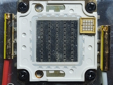
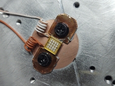
Yup. I went to HD and got a bag of very expensive copper straps. How did copper straps go from a buck fifty to five bucks? I dremeled that sucker into the right shape. Soldering was pretty straight forward. At work I use a PID hot plate or a reflow oven. But in my basemen living room garage, I have no respect for science. So I torched the baseplate. Then I carefully soldered the leads. I tested it for a couple of seconds at full power and only half of it lit up. It turns out that half the COB is pointing in the opposite direction. Then looking at the board online I realized the two sections must be in series. So de-soldered and re-soldered it.
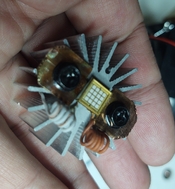
Wow, I'm really impressed. I mean both are 50W but the little one has a good 4 or 5 times the light/power intensity. Up close, 1cm, it develops new cyanotype to full Prussian white in 4 seconds. Using the 50mm lens at 25mm from the COB It is able to expose new cyanotype in 10 seconds to Prussian white. Its crazy good, 385nm supposedly. The cyanotype paper makes crinkling noises when it develops. This COB needs cooling. The little heatsink seems too small but if you think about it, it is the combination of fin area and air volume that does the cooling. So it works nice and cool piggy backed on the big fan's air stream. I'll 3D print a duct for a fan before testing the projection system. Oh man, I'm glad I got my red safety glasses for this.
Attachments
Yes, moderated by heat transfer from the COB to the radiator and from the radiator to the air. The latter is mostly determined by geometry of the radiator and airflow; the former is determined by how you mount the LED to the heat sink (and whichever mounting interfaces are between those points). That part of the construction isn't entirely clear to me, but I have some concerns there.t if you think about it, it is the combination of fin area and air volume that does the cooling.
Note that I've used high-power SMD LEDs with iffy DIY mounting only to find out that failure is something that happens gradually and within a timescale that's really inconvenient - i.e. you *think* you have a working setup, and then the LEDs start to die one by one. Maybe your setup is perfectly fine; I cannot judge. It's just a word of caution.
Yes, moderated by heat transfer from the COB to the radiator and from the radiator to the air. The latter is mostly determined by geometry of the radiator and airflow; the former is determined by how you mount the LED to the heat sink (and whichever mounting interfaces are between those points). That part of the construction isn't entirely clear to me, but I have some concerns there.
Note that I've used high-power SMD LEDs with iffy DIY mounting only to find out that failure is something that happens gradually and within a timescale that's really inconvenient - i.e. you *think* you have a working setup, and then the LEDs start to die one by one. Maybe your setup is perfectly fine; I cannot judge. It's just a word of caution.
Its fine really. It's just another few bucks down the road. I think my setup is probably very good because without the airflow the aluminum block got hot very quickly; within 5 or 6 seconds it becomes uncomfortable. So the conductivity at the joint which is the usual problem is good. They have this poor LED sitting on thin copper traces insulated by epoxy over aluminum. All the LEDs sit on a single piece of brass 4mmx4mm. So I made a strap that had a central cut out 4mmx4mm. Then I flattened it, filed it flat and polished it to 8000 on the contact side. I then cut a small piece of flux core electrical grade solder and I flattened that. I placed the LED, solder and copper on a wooden clamp such that only one copper mount wing was exposed. Then I hit that with a mapp torch watching the color change carefully. Once the LED dropped over the copper, I stopped heating and quickly used a wooden stick to correctly place the LED. Somebody wished me luck and I used all of that plus I tossed the neighbor's cat and caught it in the air thereby gaining one extra life.
When I found out I had one of the polarities backwards, I should have bonded that jumper to the 4mm ground plane. Oh well. I went searching for the picture of the board to try and guess how they did it and I wound up discovering that there are 405nm LEDs with similar footprint that go up to 400W. I am really not sure 405nm would work since 395 didn't, but these things work by specific wavelengths so it might be worth a try in the future. Hopefully I can find a 100W 385nm and run that at 50 to 80W to extend it's life next time. I'm actually not sure really what the damage threshold for all the coatings is. Their spec Max indicated 24W/mm^2 on a "similar" chip for ~400nm. 50W x1/2 over the first beam splitter minus all the light that doesn't hit the DMD and the light absorbed at the Fresnel is probably close to the limit. I'll have to judge by the results. In the previous test only 1+ pads showed on the projection @1W each. Based this new setup might get me 30W worth of pads showing.
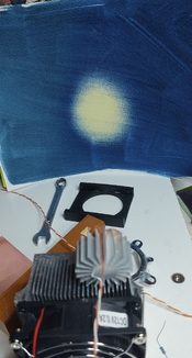
Reverse psychology. It works! This time I measured the actual temperature with the large heatsink the temp is staying pretty solidly at 43C. In the 30 seconds that measurement took, the rest of the 8.5"X11" sheet went almost fully Prussian white. Now I need a new adapter for the projector. You'll notice I mounted the chip at some angle (45 degrees). This will make the little light squares line up with the DMD chip.Sounds good; I agree that by your description the heat transfer should be excellent.
I figured going to the big heatsink will be saving time. And time is definetly something everyone can put a value on. Even me. I'm old. Middle aged. I could still date my wife if she wanted to. I bought a new heatsink for the other LED which I don't need at this moment.
Attachments
I've got to go back to the beginning of this thread. Fascinating!
The LED still works, I have yet to run it for an extended period of time. I realized the hard way that the chip stays around 43C in some areas but on the face glass, which is probably quartz, it goes to 140C - 175C. Does this sound right to anyone? I may have to run a simulation to see if this is OK. Various other chips indicate that the junction temperature is 125C for chips that produce 385nm. That's not a rule of thumb, just a couple of other LEDs that had actual documentation. Anyway, so I was placing a diffuser plastic near the front when it touched suddenly and made some sparks and smells and a tiny momentary fire. I should have known better LOL. But I just let the lamp cool down and I wiped it clean with alcohol. It appears that the damage was done though. While the chip is still intact, there is a tiny black spot in the window which is definitely a chip full or carbon most probably which will continue to damage the window until it goes thermal runaway at some point. I'm going to order another one just in case. For now the next step is to 3D print an adapter and then run the projector to make a cyanotype of the same size as before 3"X4" to compare speed. Then I'm going to take it apart again and see if I can make a diffuser that is non contact. maybe I could find a quartz diffuser or create an integrator tube like the original projector had but with reflective aluminum instead of a glass rod.
I realized the hard way that the chip stays around 43C in some areas but on the face glass, which is probably quartz, it goes to 140C - 175C. Does this sound right to anyone?
Yeah, sort of; I mean I've also noticed that the die or at least the backside of the LED's housing (that the die thermally connects to) can keep fairly cool whereas the face gets really hot.
Is that a maximum rating? Sounds like it to me.Various other chips indicate that the junction temperature is 125C for chips that produce 385nm.
Are you sure it's on the transparent casing and not on the die proper? This is a common failure mode of the semiconductor itself. I've seen it happen in lots of LEDs when the thermal design was inadequate.there is a tiny black spot in the window
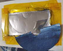
its looking good! That rectangle in pen is the size of the DMD at about the correct length. Going thru glass will make it larger.

Wow, that's hot!
Its a success Koraks! I turned the projector on with no light and the test image up, then I focused a little just to get an image on a fluorescent sheet. As soon as I turned on the LED you could see the sheet getting darker and this exposed within 10 seconds. I added a reflector cone between the LED and the lens. It may have added slightly more power but it appeared to be mostly around the perimeter of the Central LED. It was mostly trying to protect the 3D print.
As you can see the image needed a few more seconds and the light source is clearly slightly smaller than needed plus most power is concentrated at the LED spots. I got two ideas. One is a light pipe but it needs length and is lossy 85% transmission per bounce but it leaves the central portion of the power untouched. The other is to frost a microscope slide and use that as diffuser. Those things are super thin and I have a bazillion and a half. It could be more lossy but I could be wrong. Maybe I need both a cone/pipe and a frosted window near the LED.
Attachments
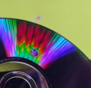
The coatings will definetly be the first thing to go. I placed this fluorescent green sheet, and this DVD at the focal point for the 50mm lens (for the current divergence its around 32mm) and the two did not survive. The DVD iridescent colors did not change from what I can tell. The polycarbonate just absorbed enough power to call it quits. This was very quick, just a few seconds. Since polycarbonate absorbs most UV, that's all it takes I guess. The fluorescent sheet just started to be less so until I started smelling something. This one took a bit more to fail like 10 to 15 seconds.
The burnt spot on the quartz window is probably just going to keep growing and accelerating until it's burnt or broken.
I polished a microscope slide with an elongated oval pattern so I can smear/stretch out the beam in one direction more. This glass did not fail like the other materials so there's some hope. It looks like I'll have to hold it in place using the aluminum cone. I don't have other materials that could survive being that close to the beam. And boy, polishing a 0.17mm thick microscope slide, that takes ingenuity. It's simple. I first found a flat piece of plastic of roughly the same size. Then I lapped that part flat to a 8000 grit stone. I tried scratching the glass using sand paper and that did not work well at all. Next you stick the slide on to a piece of kapton tape and you wrap the kapton around the flat plastic so you can wet sand/lap the slide. Its very interesting but even at 0.17mm thickness the slide showed definite signs of not being flat. I thought the plastic was the cause but I'm convinced its the glass .
Attachments
I broke the 2nd microscope slide diffuser trying to install it. Gave up for the moment and tried a plastic one which then reduced the power output. I then resorted to Blender to imagineer some sort of solution. I modeled each LED pixel, so 16 in total and I set up a screen. I'm adding various lenses to see what they do. The one from the larger 50W COB was of particular interest so then I modeled it in CAD, then exported it to blender and finally matched the index of refraction to something that gave me a similar image as to what I see on the real thing. I made the world have a fog so I can see the beam and I can see the image on this opal screen. It looks like I can adjust the lens position and get rid of the LED image. I think that's what I want to do. No diffuser. I did a search for such a thing in this forum and Koraks and some others were talking about an enlarger with a Quartz diffuser like that I initially intended, but then the consensus was that a diffuser is not needed. I also tried a reflective cone like the one I made from a soda can, and a cylinder tube as well as a rectangular tube. All these modifiers reduce the power of the central beam but add power to the vicinity. As an example below is tube with a bright circle around the square image but the central image is still clear. The rectangular tube creates a kaleidoscope image. the cone just makes a larger circle like the cylinder tube. Below is the rectangular, cylindrical integrators, no integrator and the model scene for your enjoyment. I modeled the fancy looking lens outside, the other lens I just calculated the size and curvature and created it using the Luxcore library Opticore. You just go to add->mesh->OpticoreOptics->lens and in the material you change the index of refraction as needed.


Sorry I had to share just one more image. Here you see the 16 sources sitting on the emitter's face. LOL I modeled my crappy copper cooler adapter and the face of the aluminum heatsink. It's so cool to be able to do this, many thanks to the teams who works on Opticore and Luxcore and Blender. In this image I turned off the Fog so the LED and lens can be seen as little better.

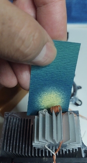
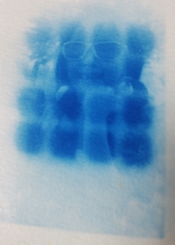
Finished my yard work today and decided to go figure out how to blend in all sources into a homogeneous blend. After some tinkering in blender it looked like just moving the 50mm lens 10mm closer would do it. I confirmed holding the lens with a folder clip and so Then printed an updated part. I used some paper sensitized last time so it's been a few weeks of citric acid fogging.
Anyway, I exposed for 20 seconds until the darks turned Prussian white. This image measures 2.5"x4". And I loved every moment of it! First off, the focusing was easy using a florescence screen, then I simply turned off the LED and swapped for the sensitive paper. Then I simply turned on the LED (safety red glasses on) and I setup a bright white light on the screen. The image started just perfect. Second 1 I could see the outline and it just sort of develops slowly in the 20 seconds frame until you got a cyanotype. This is the newcyanotype formula. The 10mm I moved the lens just makes a gorgeous homogeneous light spot in the shape of the overall LED image.
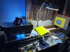
Now I need to bolt everything down to the wooden base plate and figure out what to do next. I moded this table with a vertical apron on a dovetail so the projector can project downwards. But maybe I should setup the projection horizontally to get larger images. This image was projected 15" in front of the lens. I got maximum 40" don't know the size of the image at that length but I'll figure it out. If anyone wants to try this idea I can help, but beware that the projector can cost like $100 and its limited to 1080p. With my rpi2040 program you probably don't need to get into the communication details, just solder the wires to bypass the whole ballast. Like the ballast and lamp have been physically removed. There are 4 computer fans and the color wheel that must stay connected. At 50W the DMD chip definetly needs cooling and I actually would love to add a white LED with the color wheel to project the Linux desktop in color. I've given a good look at all the fans and sensors and they are all definetly bypassable.
Anyway, I exposed for 20 seconds until the darks turned Prussian white. This image measures 2.5"x4". And I loved every moment of it! First off, the focusing was easy using a florescence screen, then I simply turned off the LED and swapped for the sensitive paper. Then I simply turned on the LED (safety red glasses on) and I setup a bright white light on the screen. The image started just perfect. Second 1 I could see the outline and it just sort of develops slowly in the 20 seconds frame until you got a cyanotype. This is the newcyanotype formula. The 10mm I moved the lens just makes a gorgeous homogeneous light spot in the shape of the overall LED image.
Now I need to bolt everything down to the wooden base plate and figure out what to do next. I moded this table with a vertical apron on a dovetail so the projector can project downwards. But maybe I should setup the projection horizontally to get larger images. This image was projected 15" in front of the lens. I got maximum 40" don't know the size of the image at that length but I'll figure it out. If anyone wants to try this idea I can help, but beware that the projector can cost like $100 and its limited to 1080p. With my rpi2040 program you probably don't need to get into the communication details, just solder the wires to bypass the whole ballast. Like the ballast and lamp have been physically removed. There are 4 computer fans and the color wheel that must stay connected. At 50W the DMD chip definetly needs cooling and I actually would love to add a white LED with the color wheel to project the Linux desktop in color. I've given a good look at all the fans and sensors and they are all definetly bypassable.
Attachments
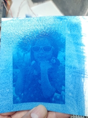
My obsession is paying off. The images appear sharper than with the original lens. Probably because it is monochromatic light this time. There are no funny smells and its as simple as turning the exposure light on and off. Since I'm using the new cyanotype formula what you see is what you get. It doesn't get darker with peroxide. So I turn the UV on and watch the magic. I can stop and take a look in normal light and I can keep exposing more if needed.
Attachments
I had a passing thought about exposing my fingers to the UV LED during the design phase trying to figure out lens position. It turns out people do get cancer of the fingers and finger nails. The wavelength 385nm is non ionizing, but that leaves big questions in my mind. I think people are getting finger cancer mostly from exposure to both UV and resins together. While measuring I would recommend to find a way to mount the lenses to something solid/temporary so you don't expose your body to relatively high power UV light. High power here is enough to catch plastic or paper on fire right at the emitter. A centimeters close by feels really uncomfortable as the divergence and scattered light warms up your skin at the surface. Definetly not a good idea to have parts of your body exposed there.
I think they separate UV ranges arbitrarily based on random phenomenon. UVC is the range that causes DNA changes. I asked our ram inhaling friends about the subject:In think the cases of cancer you talk about involve people curing fingernails for several minutes on a nearly daily basis. At least that's what I recall from reading about such cases.
- UVA: 315–400 nm
- UVB: 280–315 nm
- UVC: 100–280 nm
UVA (315–400 nm)
- Weakly absorbed by DNA
- Causes damage indirectly via reactive oxygen species
- Penetrates deep into skin
- Associated with aging and indirect DNA damage
UVB (280–315 nm)
- Strongly absorbed by DNA bases
- Causes direct DNA lesions (e.g., thymine dimers)
- Major cause of sunburn and skin cancer
- Partially blocked by the ozone layer
UVC (100–280 nm)
- Extremely strongly absorbed by DNA, RNA, and proteins
- Causes severe direct DNA damage
- Efficiently inactivates bacteria and viruses
- Completely absorbed by Earth’s atmosphere
There are a few photos on this white paper showing the effects of exposure to pig eyes. Don't worry they did not hurt a pig, They whacked the pig first. No, actually they just found the eyes by pure coincidence. I hope the pigs did not suffer, I am vegan. Try to be anyway in theory. It was totally unexpected to me that deep blue is/can be more damaging than UV.
I found that PeerTube is pretty easy to use, so I uploaded some videos to it. In these videos you can see how the UV projector creates cyanotypes. Here is one:

 vid.northbound.online
OK I uploaded one of several videos around the subject. All these show the exposure and development of Cyanotype using Mike Ware's New Cyanotype Formula mixed with polymer: CMC+PVA and developed using dilute hydrogen peroxide and then dilute citric/boric acid.
Cyanotype on CMC PVA polymer
This video shows the live exposure of an image created by a DIY UV projector. The image is created on a polymer based Cyanotypes using Mike Ware's New Cyanotype formula.
vid.northbound.online
OK I uploaded one of several videos around the subject. All these show the exposure and development of Cyanotype using Mike Ware's New Cyanotype Formula mixed with polymer: CMC+PVA and developed using dilute hydrogen peroxide and then dilute citric/boric acid.
Here are a couple of other videos with better focus and a video on how I develop these.
 vid.northbound.online
 vid.northbound.online
Slightly better focused Cyanotype exposure
Northbound's P2P video platform based on PeerTube!
vid.northbound.online
Development in Hydrogen Peroxide, Citric, Boric Acids and Water of Cyanotype
Again, this is not the normal Mike Ware's New Cyanotype Formula but an adaptation using a polymer blend of CMC, PVA, and then development in hydrogen peroxide and a dilute citric + boric acid. Both...
vid.northbound.online
| Photrio.com contains affiliate links to products. We may receive a commission for purchases made through these links. To read our full affiliate disclosure statement please click Here. |
PHOTRIO PARTNERS EQUALLY FUNDING OUR COMMUNITY:  |