albada
Subscriber
I verified that Ilford MGRC V paper performs well with pulsed light.
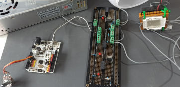
The BuckBlock A009 was smearing short pulses, dimming the LEDs, creating a mix of dimming and PWMing. That was a poor test of paper's behavior with PWM. So I pulled out the soldering iron and replaced each BuckBlock with a Mean Well LDD-700L. The new calibration curve is very close to the theoretical curve (the BuckBlock was well above it), so the Mean Well has insignificant rise/fall times, so its pulses are clean. Actually, its cal numbers are slightly low (shorter-than-expected pulses), indicating a bit of overshoot. Anyway, I re-ran the tests above. The first was trading equal amounts of LED-power and aperture to keep theoretical exposure the same, yielding these Stouffer results:

In each row, the left number is power-level of both green and blue expressed as number of stops below full power. The right number is aperture. The 0-45 exposure is repeated in the bottom row for ease of comparison with the 5-8 row above it. These rows are almost identical, showing that Ilford's MGRC V paper has no reciprocity-failure due to short PWM pulses.
The next test was trading power-level with exposure-time:

The upper row was a 1-second exposure at full power.
The lower row was a 32-second exposure at 1/32 power (i.e., the PWM pulses were approximately 1/32 of the period).
I think the lower row is a hint lighter, perhaps 0.1 stop or so. I regard this difference as insignificant. This result shows that the paper has insignificant reciprocity-failure across 5 stops of time when using PWM.
I conclude that Ilford's RC paper is well-behaved when exposed with pulsed light. And given that all papers employ similar fundamental chemistry, I suspect these results are true of all papers. Note that my PWM frequency is 122 Hz. PWM is usually faster than this, but I selected this low frequency to avoid very brief pulses at 1/32 power.
If you are making a LED-controller, I suggest avoiding any LED driver chip with a maximum PWM frequency of less than 1 KHz. The BuckBlock is 200 Hz, and the Mean Well LDD-700L chip is 1 KHz. A 1 KHz or higher frequency indicates short rise/fall times, which are crucial to getting the good results above.
The BuckBlock A009 was smearing short pulses, dimming the LEDs, creating a mix of dimming and PWMing. That was a poor test of paper's behavior with PWM. So I pulled out the soldering iron and replaced each BuckBlock with a Mean Well LDD-700L. The new calibration curve is very close to the theoretical curve (the BuckBlock was well above it), so the Mean Well has insignificant rise/fall times, so its pulses are clean. Actually, its cal numbers are slightly low (shorter-than-expected pulses), indicating a bit of overshoot. Anyway, I re-ran the tests above. The first was trading equal amounts of LED-power and aperture to keep theoretical exposure the same, yielding these Stouffer results:

In each row, the left number is power-level of both green and blue expressed as number of stops below full power. The right number is aperture. The 0-45 exposure is repeated in the bottom row for ease of comparison with the 5-8 row above it. These rows are almost identical, showing that Ilford's MGRC V paper has no reciprocity-failure due to short PWM pulses.
The next test was trading power-level with exposure-time:

The upper row was a 1-second exposure at full power.
The lower row was a 32-second exposure at 1/32 power (i.e., the PWM pulses were approximately 1/32 of the period).
I think the lower row is a hint lighter, perhaps 0.1 stop or so. I regard this difference as insignificant. This result shows that the paper has insignificant reciprocity-failure across 5 stops of time when using PWM.
I conclude that Ilford's RC paper is well-behaved when exposed with pulsed light. And given that all papers employ similar fundamental chemistry, I suspect these results are true of all papers. Note that my PWM frequency is 122 Hz. PWM is usually faster than this, but I selected this low frequency to avoid very brief pulses at 1/32 power.
If you are making a LED-controller, I suggest avoiding any LED driver chip with a maximum PWM frequency of less than 1 KHz. The BuckBlock is 200 Hz, and the Mean Well LDD-700L chip is 1 KHz. A 1 KHz or higher frequency indicates short rise/fall times, which are crucial to getting the good results above.


 But since the very small pulse width are typically something I need for RA4 paper, the issue is not a big concern anyway as those papers are these days optimized for short exposures ("digital" papers).


