Paper reciprocity-failure after only 30 seconds

Recent Classifieds

Forum statistics

Threads
199,121
Messages
2,786,462
Members
99,818
Latest member
Haskil
Recent bookmarks
0
OP
OP

albada

Subscriber
Joined
Apr 10, 2008
Messages
2,175
Location
Escondido, C
Format
35mm RF
I verified that Ilford MGRC V paper performs well with pulsed light.

The BuckBlock A009 was smearing short pulses, dimming the LEDs, creating a mix of dimming and PWMing. That was a poor test of paper's behavior with PWM. So I pulled out the soldering iron and replaced each BuckBlock with a Mean Well LDD-700L. The new calibration curve is very close to the theoretical curve (the BuckBlock was well above it), so the Mean Well has insignificant rise/fall times, so its pulses are clean. Actually, its cal numbers are slightly low (shorter-than-expected pulses), indicating a bit of overshoot. Anyway, I re-ran the tests above. The first was trading equal amounts of LED-power and aperture to keep theoretical exposure the same, yielding these Stouffer results:

MeanWell-PowerFstop.jpg


In each row, the left number is power-level of both green and blue expressed as number of stops below full power. The right number is aperture. The 0-45 exposure is repeated in the bottom row for ease of comparison with the 5-8 row above it. These rows are almost identical, showing that Ilford's MGRC V paper has no reciprocity-failure due to short PWM pulses.

The next test was trading power-level with exposure-time:

MeanWell-PowerTime.jpg


The upper row was a 1-second exposure at full power.
The lower row was a 32-second exposure at 1/32 power (i.e., the PWM pulses were approximately 1/32 of the period).
I think the lower row is a hint lighter, perhaps 0.1 stop or so. I regard this difference as insignificant. This result shows that the paper has insignificant reciprocity-failure across 5 stops of time when using PWM.

I conclude that Ilford's RC paper is well-behaved when exposed with pulsed light. And given that all papers employ similar fundamental chemistry, I suspect these results are true of all papers. Note that my PWM frequency is 122 Hz. PWM is usually faster than this, but I selected this low frequency to avoid very brief pulses at 1/32 power.
If you are making a LED-controller, I suggest avoiding any LED driver chip with a maximum PWM frequency of less than 1 KHz. The BuckBlock is 200 Hz, and the Mean Well LDD-700L chip is 1 KHz. A 1 KHz or higher frequency indicates short rise/fall times, which are crucial to getting the good results above.
 

laser

Advertiser
Advertiser
Joined
Jun 16, 2005
Messages
1,057
Format
4x5 Format
The paper emulsion builder has control of reciprocity response in the emulsion design. You would expect that the reciprocity law failure would be near zero in the 1-60 second range. Expecting B&W paper emulsions to have no reciprocity failure over several orders of magnitude may be an unreasonable expectation. Paper emulsions don't have complex doping like films so the reciprocity performance is limited.

The other factor that needs to be considered in testing is latent image. There is no mention of it.
Bob

www.makingKODAKfilm.com
 
OP
OP

albada

Subscriber
Joined
Apr 10, 2008
Messages
2,175
Location
Escondido, C
Format
35mm RF
The paper emulsion builder has control of reciprocity response in the emulsion design. You would expect that the reciprocity law failure would be near zero in the 1-60 second range...

I forgot to mention that my goal for these tests was to verify that pulsed light did not worsen reciprocity failure.

In his book, Way Beyond Monochrome 2nd ed, Ralph Lambrecht states that papers exhibit RF, even at short exposure times (under 30 sec). He even has a graph and some numbers obtained from experiments. I realized that PWM light is uncommon enough that Ilford and other paper manufacturers might not have tested their papers with such light, especially with very brief pulses. That forced me to perform the tests. As the title of this thread indicates, I saw RF at 30 seconds. But that was with BuckBlock drivers smearing pulses, dimming them. Changing to Mean Well drivers eliminated almost all RF. That brings us to an interesting tentative conclusion:

Pulsed light reduces reciprocity failure.​

Additional tests should be done to verify that conclusion. But I have verified that PWM doesn't worsen RF. I'm happy with that.
Mark Overton
 
OP
OP

albada

Subscriber
Joined
Apr 10, 2008
Messages
2,175
Location
Escondido, C
Format
35mm RF
I might have missed the essence of one of the earlier posts, but isn't it more like your other conclusion: pulsed light (within a certain margin) does not necessarily produce short exposure reciprocity failure?

Yes, that is a reasonable conclusion. In addition, the BuckBlock with its dimming+lengthening of short pulses showed some RF across 5 time-stops. The same test with the clean-pulse Mean Well shows minimal RF. Hence my tentative conclusion that (clean) pulsing reduces RF. However, Nicholas Linden's testing using tungsten (documented here: http://www.darkroomautomation.com/support/appnotereciprocityandintermittency.pdf) showed no RF across 8 time-stops. Yet Lambrecht's book contains a graph and data on RF, even for normal exposure times. More testing is needed to resolve these contradictory observations.

But the testing I've done suggests the mp24894 you are planning to employ will give fine results, as its rise/fall times must be very short in order to support a maximum PWM frequency of 20 KHz.

You have mentioned short exposure RF a couple of times. Do you have details about that? My shortest pulse is 0.26 ms (=1000/(122.4*32)), and I'm wondering how short I can go before encountering that kind of RF.
 

koraks

Moderator
Moderator
Joined
Nov 29, 2018
Messages
23,282
Location
Europe
Format
Multi Format
But the testing I've done suggests the mp24894 you are planning to employ will give fine results, as its rise/fall times must be very short in order to support a maximum PWM frequency of 20 KHz.
I hope so :wink: But since the very small pulse width are typically something I need for RA4 paper, the issue is not a big concern anyway as those papers are these days optimized for short exposures ("digital" papers).
Some research into short exposure reciprocity failure was done in the 1940s-1950s, see e.g. here: https://core.ac.uk/download/pdf/142083435.pdf
I'm not sure what happened on the topic after that. Obviously emulsions have changed, but to what extent this issue was addressed in b&w printing papers, I really don't know.
 

138S

Member
Joined
Dec 4, 2019
Messages
1,776
Location
Pyrenees
Format
Large Format
This is an open-loop design that relies on having good regulation in the supply and no significant thermal-drift in any component. I envision the PWM frequency being around 50-100 KHz, and the inductor L large enough so that LED-current will have only a small ripple.

The coil and the freewheel diode you add is an smart solution to adjust intensity and to avoid ripples...

Anyway let me point that there is an alternative: not avoiding ripples at all and lowering PWM to about 500Hz or 200Hz, allowing the duty cycle duration to be longer than 1ms.

This alternative approach has the advantage to avoid LIRF (reciprocity failure) because when we illuminate we do it at full power, the PWM allows having time enough for the image manipulation (dodging/burning/etc) but we don't provocate the nasty side effects of the low light intensity.

That switching won't be perceived by the human eye, the resulting flashes won't be seen in the burning/dodging because the casted shapes are not in focus, and it makes easier to print highlight detail from avoided LIRF.
 
OP
OP

albada

Subscriber
Joined
Apr 10, 2008
Messages
2,175
Location
Escondido, C
Format
35mm RF
Without the coil, the entire 24 volts of the power-supply would be dropped across the LED-string, resulting in a huge current. At 500 Hz, that huge current would last for a fraction of a ms, which could damage the LEDs. Did I misunderstand? Were you thinking of another method of limiting LED-current?

I think most LED controllers use both methods. They use square-wave pulses with a frequency of 100kHz to 1mHz with an inductor and freewheel Schottkey diode to provide a steady regulated current, and then they switch that current with a PWM from an external source having a much lower frequency. The datasheet for the MP24894 that koraks is planning to use is well-written and interesting: https://www.monolithicpower.com/en/...tasheet/lang/en/sku/MP24894/document_id/2052/
 

138S

Member
Joined
Dec 4, 2019
Messages
1,776
Location
Pyrenees
Format
Large Format
Without the coil, the entire 24 volts of the power-supply would be dropped across the LED-string, resulting in a huge current. At 500 Hz, that huge current would last for a fraction of a ms, which could damage the LEDs. Did I misunderstand? Were you thinking of another method of limiting LED-current?

A discrete LED can take and unstable amount of current and it requires a regulation, the classic way is a series resistor for the regulation...

Anyway you don't need a coil to obtain a regulation, or you may place the coil and the freewheel diode in a way allowing a pulsed operation.

In general, a pulsed LED operation is not only possible but it also can be necessary, an example is the TV remote command where the IR LED has to encode a digital message, but also for technical illumination it can be useful, I often make LED illuminators (in my job) for machine vision for machine vision systems and those throw strobes when the video camera is taking an image. Imagine we take 30 fps, each exposing for 1ms... in that case we throw 30 strobes of 1ms per second, one for each image frame. so the LED is working 30ms each second, this is around 1/30 of the time. If we trigger short pulses to the LED then we can even throw x10 more current/light per led, so we can save 90% of the LEDs in the illumintor or we can shorten exposure time to 10%... avoiding 90% of the motion blur.

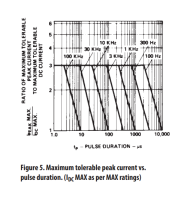
In the datasheet we may find the allowed overcurrent for pulses, depending on the duty cycle, the Hz, temperature... this crop shows the pulse can throw x3 more instant power than the allowed one in the continuous operation...


upload_2021-4-9_16-24-58.png


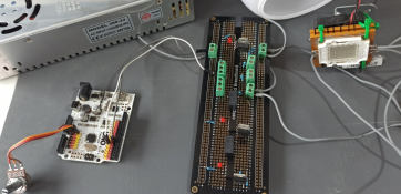
Next image shows materials of preliminary test I made time ago with a RGB LED chip. The LED chip consists of arrays of LED and do not require a current regulation, you simply use the nominal voltage, the portrayed LED chip has a common positive so 3 MOSFETS (R,G,B) are used for switching between the each channel and ground, the used MOSFET is VNP5N07P which is fully autoprotected Omnifet marvel (ESD, Thermal, overcurrent, internal Zener) which is virtually indestructible, the potentiometer only tells the arduino what desired duty cycle was desired in the tested channel...

upload_2021-4-9_16-22-51.png

This was the basis for an illumination retrofit in a Durst 138, finally I opted for a pulsed operation to avoid paper's LIRF. I've pending measuring the exact LIRF avoiding effect which is significative for sure, still there is no doubt those easily available LED chips can be operated in pulsed mode with no problem, without series resistors or coils.

______

If a discrete LED requires a regulation then we have several ways to use it in a pulsed operation, the easy one is using a power supply having a capability matching the wanted limit, and we always may use a resistor in series with the series LED array. When we have a n array of LEDs in series regulation is less needed, this is the case of those LED chips that arrange many LEDs in series...
 
Last edited:

koraks

Moderator
Moderator
Joined
Nov 29, 2018
Messages
23,282
Location
Europe
Format
Multi Format
the portrayed LED chip has a common positive
It may be convenient to know that if you cut the positive terminal between the 3 prongs that go into the COB chip, you essentially have 3 separate led arrays, one for each color. They can then be fed with the appropriate voltage for maximum efficiency for each array and switched at the cathode as well with an N-channel fet or NPN bjt or p-channel devices if you so prefer. I did this in my first led enlarger tests. The only reason I didn't use this in the final version was that the colors weren't appropriate for RA4 printing, resulting in unfixable crossover. Otherwise it worked fine; it should do quite ok for b&w.

Btw, I find your remarks on driving leds at multiple times their specified current remarkable; I've destroyed a dozen or so leds as they tended to break down within a few milliseconds at 3 times or so their specified current. It's always one or two leds in the array failing open leaving the others unaffected, so with discrete leds repairs can then be made,but I did go for separate current sources for each individual led array to prevent cascaded failures in my present led source project.
 
Last edited:
OP
OP

albada

Subscriber
Joined
Apr 10, 2008
Messages
2,175
Location
Escondido, C
Format
35mm RF
I opted for a pulsed operation to avoid paper's LIRF...
Do you have information or measurements or photos of the reciprocity failure you saw? Earlier in this thread, I posted an example of RF with wide pulses (caused by low slew rate) and no RF with shorter pulses (high slew rate). Do you have examples of both?
 

138S

Member
Joined
Dec 4, 2019
Messages
1,776
Location
Pyrenees
Format
Large Format
Btw, I find your remarks on driving leds at multiple times their specified current remarkable; I've destroyed a dozen or so leds as they tended to break down within a few milliseconds at 3 times or so their specified current. It's always one or two leds in the array failing open leaving the others unaffected, so with discrete leds repairs can then be made,but I did go for separate current sources for each individual led array to prevent cascaded failures in my present led source project.

koraks, there is a way to safely boost pulsed overcurrent through a LED, it is the way I used in the designs I made for machine vision illuminators, I just copied other popular designs I saw around...

> Power source has the Amp capability matching what the LEDs can safely stand, this is a safety belt that will intrinsically prevent throwing an overcurrent.

> A suitable resistor follows and then a capacitor. When you switch ON then the LED is sourced from the capacitor thus limiting the amount of electric charge that it will be sourced to the LED during the pulse. The LED charge is soon exhausted as it only can store the power for the pulse and then the mentioned resistor limits the current well under LED's nominal current so if the switching OFF fails the LED won't be burnt. During the OFF state the capacitor is carged again and it is prepared for a new duty cycle:

upload_2021-4-10_11-33-11.png

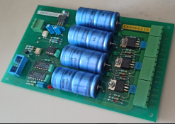
This is a 20 years old LED flash unit board to do that, I have it in the trash right now. For computer vision, time ago it was very important to be able to throw overcurrent pulses because some specialty LEDs of certain required wavelength were very expensive, so saving LEDs and space was a key factor.

upload_2021-4-10_13-53-56.png

In this case the cap battery has around total 19 milli Farads which at 24V can store some 0,450 Coulomb. It can source 0,45 Amp for 1 second but if discharge time was 10 millisecond... then 45A were sourced for the pulse with 1Kw instant LED power equivalent to perhaps 8Kw halogen. Well, this was an spare for a big machine... Just to illustrate that pulsed-boosted illumination has been used since several decades ago... and that's the reason why datasheets for technical LEDs provide information for its pulsed-boosted usage.

The capacitor has to be calculated to be able to source enough charge for the intended pulse, and the Resistor has to be calculated to allow the capacitor be charged in the OFF cycle, while the P

S + R not being able to burn the LED in any situaction including DC. For example when I debug Arduino in the Atmel Studio and in a break point switching may remain permanently ON, but no problem... a permenent ON is not to burn the LED, while the pulsed overcurrent can be used.


Do you have information or measurements or photos of the reciprocity failure you saw? Earlier in this thread, I posted an example of RF with wide pulses (caused by low slew rate) and no RF with shorter pulses (high slew rate). Do you have examples of both?

RF is short for LIRF, low intensity reciprocity failure. What causes the failure is not the pulse width but the low intensity. You need several photons (three, or less in some advanced emulsions) to reach a crystal to mark it electronically. Failure happens when intensity is low so when a second or third photon arrives the energetic effect of the first photon may have disapeared yet and exposure is slower than in regular conditions.

Extremly short pulses (beyond say 1/1000s + 1/10,000s) may also deliver a failure as fim datasheets may state, but let's focus in a (say) 1/500 switching provocating no failure from pulse shortness.

In that case you will have the same reciprocity behaviour with 2ms pulses than with 300ms pulses, provide the total emited photons are the same amount.

Problem hapens when you decrease light intensity to extend exposure time to the point paper LIRF is evident, which hapens with a desing intended to sustain a lower intensity. Say you extend exposure from 20s to 80s, your low ripple current will continuously source 1/4 of the initial light intensity: Low intensity = reciprocity failure. Instead if you throw all the intensity pulsed in 1/4 duty cycle pulses for those 80s then you will avoid the failure because when you switch ON you don't have Low Itensity, so you don't take reciprocity failure. It is not about the duration of the pulses, it is about the intensity. Of course this is mostly noticed in the highlight detail, thus in the paper toe, but not in the scene shadows that are in the thin areas of the negative allwoing a higher light intensity. LIRF happens if we have local low light intensity provocated by the combination of low_illumination_power / low_aperture / negative_density. All added tells if we are in LIRF conditions.

________________________

Yes, I made paper calibrations with 200Hz pulsed light compared with continous, measuring with a lux meter to get the same average, and continous shows a very clear density loss in the last patches of the stouffer's contact copy at 160s exposure (single extreme test I made), compared to 1/8 (3 stops) pulsed to extend 20s to 160s conserving same exposure but extending manipulation time to 160s. This was an extreme test, I've pending making more accurate tests to learn more, mostly intended to scale prototype prints to big prints exposed on the wall, in order to nail the same job worked in small scaled prototype prints. Today we have cheap/powerful LEDs (low heat) allowing a nice illumination deal on the wall, but scaling up a prototype to the wall IMO requires learning some skills (I still don't have) if we want to be efficient.
 
Last edited:

koraks

Moderator
Moderator
Joined
Nov 29, 2018
Messages
23,282
Location
Europe
Format
Multi Format
A suitable resistor follows and then a capacitor.
Yes, that does the trick. I just ran a quick spice sim with some fairly random components (12V power, a 175mA led, 120R resistor and 470uF cap and an NMOS as a low-side switch) which creates some nicely short spikes of about 10ns at roughly 1.6A while stable current during the on-pulse (duty cycle 50%, 500Hz) is around 150mA. I imagine it works perfectly for your machine vision applications.
Of course for photography it's a little less relevant as a normal (non-RC augmented) PWM drive works just fine; we don't really need the high current pulses in our application.
Besides, for many leds, particularly those sourced cheaply and directly from China, it's impossible to find a good datasheet, let alone one that gives data on permissible pulse currents.
 
  • 138S
  • 138S
  • Deleted

RalphLambrecht

Subscriber
Joined
Sep 19, 2003
Messages
14,658
Location
K,Germany
Format
Medium Format
Reciprocity failure isn't a function of time but of light intensity falling on the media.
That's my understanding too but it's still a bit of a conundrum. What do we know is: exposure[H] is the product of light intensity and exposure duration(time)[t]>H=I*t. As long as the product is the same, the exposures the same. So in theory, intensity goes down all one has to do is to increase the exposure time and exposure will stay constant. Practice, is intensity is very low as inLIRF, sibling Chris in exposure time is insufficient to compensate for the lack of light intensity. Similarly, light intensity is very high as in electronic flash exposure, we experienceHIRF and the mathematically correct brief exposure time again leads to under exposure. Both cases, suppose your time needs to be adjusted to lead to correct exposure. From this one can see how one can incorrectly interpret exposure as a function of time.
 
Photrio.com contains affiliate links to products. We may receive a commission for purchases made through these links.
To read our full affiliate disclosure statement please click Here.

PHOTRIO PARTNERS EQUALLY FUNDING OUR COMMUNITY:


Ilford ADOX Freestyle Photographic Stearman Press Weldon Color Lab Blue Moon Camera & Machine
Top Bottom