OM-1n Light Meter - Changing Resistor Values to Adapt Meter to Operate with Silver Oxide Battery

Recent Classifieds

Forum statistics

Threads
197,580
Messages
2,761,331
Members
99,406
Latest member
filmtested
Recent bookmarks
0
OP
OP

back2vinyl

Member
Joined
Jan 3, 2023
Messages
11
Location
Cincinnati
Format
35mm
OP, I presume you want to sell your solution. Folks are interested in solving their problem with a different solution if the newer solution is either
  • technically better
  • cheaper to use
  • some other advantage over the pre-existing solutions
So which of those benefits applies, which would make OP's solution worth bringing to market? Where is OP's product's position in the marketplace going to be? Or is this simply an engineering exercise, and not intended to be offered to buyers?

I have zero interest in selling anything. I was just curious what values to use in the resistor circuit to make it work with a silver oxide battery. I also wanted to improve my understanding of how light meters work, and this seemed like a good way to do that. When you own old stuff, it can pay to know how it works in case it breaks.
 

wiltw

Subscriber
Joined
Oct 4, 2008
Messages
6,364
Location
SF Bay area
Format
Multi Format
I have zero interest in selling anything. I was just curious what values to use in the resistor circuit to make it work with a silver oxide battery. I also wanted to improve my understanding of how light meters work, and this seemed like a good way to do that. When you own old stuff, it can pay to know how it works in case it breaks.

Good to have natural curiosity, and the desire to engineer your own version of a solution to a problem. I know Wheatstone Bridge circuits are not subject to variation caused by Voltage changes, but the OM-1 doesn't use that circuit type. Just keep in mind what I already found (and mentioned in this thread)...OM-1 metering 'error' -- due to use of any battery voltage other than 1.35V -- is variable dependent upon intensity of the light being metered...so would your design be immune to that variability?
 

MattKing

Moderator
Moderator
Joined
Apr 24, 2005
Messages
51,996
Location
Delta, BC Canada
Format
Medium Format
Another chapter is the let's make it as complicated as possible saga.

The OP posted: "I’m pretty confident that this method will work, but the question remains, is it worth doing? Truth be told, I’ll probably just buy the diode based adapter rather than try and modify the circuit board. But I like knowing how it could be done."
Emphasis added.
Not necessarily a practical solution for the owners of a single camera, but an interesting solution for anyone trying to deal with 40 cameras (e.g. a school program wanting to refurbish a cache of OM-1s).
The reason I'm intrigued is because it helps one understand the fact that many/most metering circuits are voltage dependent. Of course, in my youth I used to enjoy using a soldering iron.
 

Jimskelton

Member
Joined
Jan 16, 2023
Messages
46
Location
Alberta, Canada
Format
Large Format
This is interesting. I have a couple of OM-1's so if you come up with replacement R values, that would be fun to modify them for silver oxide batteries. Pragmatically, diode adapters seem to work within film exposure tolerances, but they are subject to temperature, and don't technically regulate voltage to 1.35 volts. They only reduce voltage depending on the current draw of the circuit. Ideally you would want to determine upper and lower current levels of the circuit at extreme EV levels, then use a diode which will give you the best voltage drop between those values.

So keep on experimenting! Understanding these camera circuits adds richness to this forum and knowledge for future research.
 

Ivo Stunga

Member
Joined
Apr 3, 2017
Messages
1,151
Location
Latvia
Format
35mm
I bought and use that diode adapter and my exposures are decent enough to allow metering for slides. But this - way above my head and I'm impressed, will be watching this thread.

But the reason I'm writing this is - I had silver OM-1 and that wire attached to the rotating exposure needle housing just gave up, killing the exposure metering system. So when I received my black OM-1n, I immediately readjusted that wire position to relocate the stress zone to a fresh part of the wire and this should prevent this problem from reoccurring - this idea might be of use to somebody.

but they are subject to temperature
In practical terms - is that influence felt? Colder temperatures results in reported underexposures? Because I've wondered in those very cold days if that snow I just exposed to EV+1 should've been a tad brigter?

And by what degree does the measurements fluctuate in temperature range of +35C to -20C? Now I'm curious!
 
Last edited:

koraks

Moderator
Moderator
Joined
Nov 29, 2018
Messages
20,933
Location
Europe
Format
Multi Format
Ideally you would want to determine upper and lower current levels of the circuit at extreme EV levels, then use a diode which will give you the best voltage drop between those values.

If you like to do the exercise with a piece of paper and a pocket calculator, you could determine this based on the schematic and measurements posted. A ballpark estimate based on eyeballing the schematic suggests that the worst case current draw is around 100uA and I'd be surprised if the lower bound is much less than 10uA or so. In practice that's low enough to be able to rely on the forward voltage you can get with DMM measurement of the diode.

And by what degree does the measurements fluctuate in temperature range of +35C to -20C?

That's actually a slightly complicated question, but here's a start to the argument. A diode has a temperature-dependent voltage drop; here's e.g. a small family of curves for the popular BAT54C Schottky diode:
1674806633068.png

Note that given the low current, the bottom left corner is the area of interest. You'd be operating the diode in the area roughly between the 25C and -40C curves. As you can see, there's a small but significant difference in forward voltage.

You could work out the influence on meter readings by combining the extreme cases (lowest and highest voltage drop) with the information in from the circuit and the typical LDR values reported earlier in this thread. Being of the lazy persuasion, I haven't done this, and if I were pressed to, I'd run it through LTSpice instead of doing the math manually :smile: 
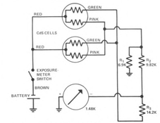
This would give the currents that the ammeter sees, and you could then compare these with the currents you get with different LDR values in the situation with a nominal 1.35V supply to the network.

Without saying anything about the magnitude of the effect, the notion that colder temperatures result in underexposures would make sense - the voltage drop is lower in the diode, the ammeter as a result sees a higher current and gives a higher meter reading than it should, so you'd end up underexposing the shot. By how much? That's what the exercise outline above would have to show. Note that this does depend (somewhat) on the exact type of diode used.
 

Ivo Stunga

Member
Joined
Apr 3, 2017
Messages
1,151
Location
Latvia
Format
35mm
the notion that colder temperatures result in underexposures would make sense

I did the next best thing after math (skipped classes starting from 5th grade, retard ever since) - an experiment.
Took my camera out of my bag, measured the camera temperature with FLIR: 19,7°C
Will be using monitor as constant brightness source, it measures 1/30 @f/2.0 as EV0
This gives room temperature control to measure against: 1/30 | f/2.0 | 20°C

To better detect the possible deviation in cold, I
- took out the battery parts (battery, adapter, cover), put them outside on windowsill for 30 min, 0°C
- rushed the battery parts back with minimal touching, needle now reads ~1/3 lower than control! That's equal of 1/3 of an exposure.

To model this closer to winter reality
- placed the whole camera outside for 42 min, 1°C
- measured the monitor: needle now points about a 1/2 lower from control - exposure time halved!

----

To see the level of deviation in heat
- placed the battery parts on a 35°C heating pipe for 10 min; camera left in room temp.
- measured the monitor: same as control - parts probably didn't heat up enough.

To model this closer to summer
- placed the whole camera on 42°C heating pipe for an hour, camera body reads now solid 30°C
- measured the monitor: EDIT: 1/4 higher


This tells me that I have to be conscious about cold temperatures and in extreme cases take that into account and compensate accordingly.
Thanks for this!
 
Last edited:

koraks

Moderator
Moderator
Joined
Nov 29, 2018
Messages
20,933
Location
Europe
Format
Multi Format
Cool! I didn't want to suggest running that experiment, but it crossed my mind :smile: Nice that you tested it, and it shows that the deviation certainly is serious enough to become a problem. I guess the low-drop regulator mentioned here and elsewhere by @ic-racer (if memory serves) is a much better idea, and almost as easy to implement.
 

Ivo Stunga

Member
Joined
Apr 3, 2017
Messages
1,151
Location
Latvia
Format
35mm
After camera cooled back to room temp, I measured again and did edit my post. At 30°C needle points 1/4 higher than control. Negligible error in summer, large in winter, noted.

"low-drop regulator" you say? : )
 

Ivo Stunga

Member
Joined
Apr 3, 2017
Messages
1,151
Location
Latvia
Format
35mm
Filip Dee in a camera repair group on Facebook mentioned that he had a circuit board produced for a voltage regulator that provides exactly 1.35 volts. (He also had 2.70 volt boards produced).

So I bought a handful of each and am planning to put it in my OM-1.

The disadvantage of this design is a slight current draw. So if there isn’t already a switch in the camera or meter, one will have to be put in.

OM-1 has a switch but in the mercury days you really never had to turn it off. The battery lasted a long time anyway. With this board in, you will want to turn that switch off when not in use.

The camera won’t need to be recalibrated because it’s exactly 1.35 volts.

How do you apply this mod? A simple wire resoldering job to hide somewhere in that body?
 

koraks

Moderator
Moderator
Joined
Nov 29, 2018
Messages
20,933
Location
Europe
Format
Multi Format
"low-drop regulator" you say? : )

Well, not entirely accurate; I think it's a buck-boost regulator. See in this thread: https://www.photrio.com/forum/threa...re-meter-conversion.84441/page-3#post-2630285
But that doesn't help too much in terms of tracking down the component, but this does give a little more to go on: https://www.ebay.com/itm/125393135164
With a parametric search on the sites of radioshack, Mouser or Farnell I suppose I could track down a suitable component, but haven't looked into it yet. If you want, I could give it a go.
 

Ivo Stunga

Member
Joined
Apr 3, 2017
Messages
1,151
Location
Latvia
Format
35mm
Well, considering these 3 issues, I currently ask about these just out of my curiosity - I would love to continue using my tight adapter to fill the chamber accordingly - hate flimsy stuff. So I'm not really a buyer, because I already have that diode adapter.

1. I know now experimentally that with said adapter I have to give an extra thought about metering just during winter, making it a far lesser of an issue for me, because I tend to shoot far less in winter.
2. For best metering a silver cell is required for stable voltage through the lifetime of the battery. You can't just pop in alkaline and expect good metering performance.
3. Silver batteries of such size and shape aren't being produced, so an adapter or a gasket is needed to hold the battery sandwiched between contacts. I hate flimsy stuff - did I said that?
 

Chan Tran

Subscriber
Joined
May 10, 2006
Messages
6,660
Location
Sachse, TX
Format
35mm
Correct me if I am wrong. What you did depends on the silver oxide battery voltage is 1.55V throughout it's useful life?
 

faberryman

Member
Joined
Jun 4, 2016
Messages
6,048
Location
Wherever
Format
Multi Format
How did you measure the 1/2, 1/3 and 1/4 exposure variations? Were you measuring electrical output or physical needle deflection?
 

Ivo Stunga

Member
Joined
Apr 3, 2017
Messages
1,151
Location
Latvia
Format
35mm
Just needle position - something anyone using such an adapter can understand an be prepared for to compensate in freezing cold.

This might help - say divide the range from the center position to a full stop under in 4 parts. When the needle touched the "gate", I called it a 1/2 stop deviation as illustrated in the attachment below.

With color and BW negs you'll hardly feel the difference - carry on as before.
With slides - 1 stop difference is quite dramatic and 1/2 deviation can be easily spotted. 1/3 - not so much.
 

Attachments

  • OM metering needle positions.jpg
    OM metering needle positions.jpg
    9.9 KB · Views: 56

faberryman

Member
Joined
Jun 4, 2016
Messages
6,048
Location
Wherever
Format
Multi Format
Just needle position - something anyone using such an adapter can understand an be prepared for to compensate in freezing cold.

This might help - say divide the range from the center position to a full stop under in 4 parts. When the needle touched the "gate", I called it a 1/2 stop deviation as illustrated:

I understand. I have been using an OM1 since the 1970s.

My experience is that it is rare when metering a scene that the needle is exactly in the center. The only way to get the needle exactly in the center is to set the aperture between stops. Since the physical distance between stops is small, that requires some precision. If you are in cold or hot weather, you can adjust the ASA dial to compensate for temperature variation, but not in 1/2 or 1/4 stop increments. You can only adjust it in 1/3 stop increments. Of course, three 1/3 stop clicks is one stop.

Since the OM1 has a center weighted average meter, metering is not really all that precise anyway, which is why I moved to an OM4 with spot metering.

I never noticed any exposure errors due to temperature variation when using my OM1, but I understand your desire for precision.
 
Last edited:

Ivo Stunga

Member
Joined
Apr 3, 2017
Messages
1,151
Location
Latvia
Format
35mm
It happens, but I adjust between stops only when 1/2 point is reached and only with apertures - works for me, guess we've learned each other's quirks. And when in doubt - usually an app or DSLR tells me that I have no reason to doubt.
 

faberryman

Member
Joined
Jun 4, 2016
Messages
6,048
Location
Wherever
Format
Multi Format
And when in doubt - usually an app or DSLR tells me that I have no reason to doubt.

Assuming the app or DSLR meters is accurate.

I have casually tried a couple of exposure apps and they seem pretty good. If I didn't have a meter, I would use one of them over Sunny 16 any day. If I were shooting with my OM1, I wouldn't carry a DSLR around with me to double-check my OM1 meter readings. You know the old saying: "A man with one watch always knows what time it is. A man with two watches is never sure.”
 
Last edited:

Ivo Stunga

Member
Joined
Apr 3, 2017
Messages
1,151
Location
Latvia
Format
35mm
Who said carry? A test with app here, a test with DSLR at home... Sufficient enough to verify readings. One film camera on me + potato in my pocket is plenty of camera for me.
 

faberryman

Member
Joined
Jun 4, 2016
Messages
6,048
Location
Wherever
Format
Multi Format
Who said carry?
Erroneous assumption on my part. I thought you would be carrying the app or DSLR with you so you could make the appropriate adjustment to the OM1 meter readings as the weather warmed up during the day. For example, it was 29F this morning at 7:00am and is 50F now at noon. It will warm up further as the day wears on, before cooling back down in the evening. If you double check your OM1 meter readings with the app or DSLR before you leave in the morning, I guess you could just check the temperature on your phone to determine the appropriate adjustment needed to the OM1.
 
Last edited:

Jimskelton

Member
Joined
Jan 16, 2023
Messages
46
Location
Alberta, Canada
Format
Large Format
I measured the actual current draw of the meter circuit in an OM-1n. With the lens cap on: 10uA. Pointed to the sky: 188uA. From the attached chart, it appears the MR9 adapter works fine up to around 130uA, at which point voltage drops off dramatically. At the lower end (in low light, voltage is around 1.45v which is a little high. It looks like a better choice of diode would be the BAT43 schottky diode, which looks like it only varies between 1.4 and 1.33 volts.

Back to the original subject. I suppose the resistors in the OM-1 circuit could be temporarily replaced with some POTs. Then, when using a bare silver oxide cell, vary the resistance on the POTs until the meter points to the correct exposure. I have a feeling it would take a bit of trial and error since CdS cells (is this what the OM-1 has?) don't have a linear variation of resistance in relation to the light falling on it.
 

Attachments

  • diodes.jpg
    diodes.jpg
    66.7 KB · Views: 48

Ivo Stunga

Member
Joined
Apr 3, 2017
Messages
1,151
Location
Latvia
Format
35mm
I just gave a thought about the direction the exposure should be compensated for in freezing cold and funny enough - it has a complimentary nature! Meaning: winter has a increased chance of... cold and snow (and drab lighting throughout most of the season where I live).
Knowing that in the cold the diode adapter reports underexposure, chances are that this error will be beneficial for practical photography as it requires increased exposure time/aperture to arrive at "EV0". And so does the snow filled scenes! If exposed without compensation, chances are the exposure meter will read snow as the middle value, exposing it as such. Resulting in gray and lifeless image with dull highlights. To avoid this, increased exposure time/wider aperture is needed - making this a self-correcting error for snowy scenes : D

Because if in room temperature camera reports 1/30 @f/2 and cooled camera reads by 1/3 of an exposure lower, to have a "correct" reading I have to increase my exposure time by 1/3 (impossible(?) with this camera) or adjust aperture in-between the clicks (quite easily doable if aperture ring in good working order).
 
Last edited:

Bill Burk

Subscriber
Joined
Feb 9, 2010
Messages
9,153
Format
4x5 Format
How do you apply this mod? A simple wire resoldering job to hide somewhere in that body?

It’s a tiny board that needs a good hiding place and you make three connections. It gets its own connection to the battery (switched if possible) then the other connection goes to the circuit.
 

Jimskelton

Member
Joined
Jan 16, 2023
Messages
46
Location
Alberta, Canada
Format
Large Format
Again, back to the original topic (if you are not sure, read the first post):

Ok, so I took apart my original OM-1, disconnected the wires to the "circuit board" (basically just 3 resistors connected to the CdS's and galvenometer) and connected them to a breadboard so I could swap out resistors until the meter read correctly with a 1.55v silver Oxide battery.

You may notice that working on this camera takes only basic soldering skills. There are no surface mounted components or ribbon cables. Just wires and resistors. You may also notice that whoever assembled the board did a fairly sloppy job soldering the resistors on, and that R3 is actually 2 resistors in series (around 16.3K and 4.7K), which may mean they were adjusting the meter at the factory until they got it right.

The R values in this model were a different than the diagram, which tells me they needed to dynamically adjust these values to work with whatever CdSs came off the assembly line:

R1 (middle adj): 8.2K (spec 6.9K)
R2 (high adj): 12.7K (spec 9.8K)
R3 (low adj): 21K (spec 14.2K)

Lowering R1 lowers the current going through the galvanometer (meter needle). Raising R2/R3 also lowers the high and low light current levels.

I just did some quick tests at EV15, EV9, and EV5 at ASA 400 and came up with the following values that seem to work for now. I'll be doing much more thorough testing/tweaking at each EV number to be sure this will work through the whole range:

R1: 3.3K
R2: 10K
R3: 22K

What this tells me is that R1 has an overall effect on the circuit, and lowering it probably bleeds out current to ground preventing it from going to the meter.

The funny thing about this camera is that I forgot I installed a diode to correct the voltage at the battery terminal. When I took meter readings it was off by 1/2 to 1 stop at both ends, and not overall high, which confused me at first, until I measured the voltage (varied between 1.4 and 1.33 volts). I was never happy with the way it worked because it seemed to only give me accurate meter readings around EV 8 or 9. So hopefully changing out a resistor or 2 will be a better solution. I'll update when I finish with the more thorough testing.

One last note: perhaps those who would like to discuss other methods of compensating for the higher output of silver oxide batteries (such as MR9 diodes or voltage regulators) could do so in another thread. It almost seems like this thread got hijacked by those who are not really interested in discussing the original topic.
 

Attachments

  • OM1 circuit.jpg
    OM1 circuit.jpg
    21.2 KB · Views: 73
  • OM-1 camera.jpg
    OM-1 camera.jpg
    100.7 KB · Views: 68
  • OM-1 board.jpg
    OM-1 board.jpg
    100.6 KB · Views: 68
Photrio.com contains affiliate links to products. We may receive a commission for purchases made through these links.
To read our full affiliate disclosure statement please click Here.

PHOTRIO PARTNERS EQUALLY FUNDING OUR COMMUNITY:


Ilford ADOX Freestyle Photographic Stearman Press Weldon Color Lab Blue Moon Camera & Machine
Top Bottom