Mamiya C330 focusing

Brentwood Kebab!

A
Brentwood Kebab!

  • 1
  • 1
  • 51
Summer Lady

A
Summer Lady

  • 0
  • 0
  • 59
DINO Acting Up !

A
DINO Acting Up !

  • 1
  • 0
  • 36
What Have They Seen?

A
What Have They Seen?

  • 0
  • 0
  • 51
Lady With Attitude !

A
Lady With Attitude !

  • 0
  • 0
  • 46

Recent Classifieds

Forum statistics

Threads
198,766
Messages
2,780,605
Members
99,701
Latest member
XyDark
Recent bookmarks
0

Smudger

Member
Joined
Aug 9, 2004
Messages
303
Location
Dunedin,New Zealand
Format
Multi Format
To PeterB - I wasn't addressing your problem,but the Original posters.His image didn't look properly sharp when correctly focused. Are you seriously suggesting that a magnifying lens can be used for critical focusing even when not focused on the ground glass?
That is equivalent to dialling out a viewfinder dioptre adjustment, or using a focusing loupe set wrongly.
You can do it,but WHY?
 

PeterB

Member
Joined
Apr 3, 2005
Messages
644
Location
Sydney, Aust
Format
Medium Format
To PeterB - I wasn't addressing your problem,but the Original posters.His image didn't look properly sharp when correctly focused. Are you seriously suggesting that a magnifying lens can be used for critical focusing even when not focused on the ground glass?
That is equivalent to dialling out a viewfinder dioptre adjustment, or using a focusing loupe set wrongly.
You can do it,but WHY?

Hi Smudger, thanks for clarifying your response, apologies for suggesting your premise was false as you weren't answering my question but the OP's.

I'm certainly not suggesting the magnifying lens remains out of focus at all ! And if it is out of focus, by all means fix it. In my case I have a bigger problem to fix first (the discrepancy btwn WLF focus and film plane focus). My magnifying lens may or may not be optimised but to my eyes it is good enough for now while I solve the main problem.

My measurement results are becoming more and more confusing. Last night I repeated the testing inside to discover that focussing on objects at 3m and 15m did not give the discrepancy (but focussing at objects 60cm away did). Whereas a couple of days earlier when testing outside (on different objects), the discrepancy existed at 3m and infinity (I didn't test 60cm outside). In all cases when the discrepancy exists it is approx. the same magnitude and direction.

Something must be changing between my measurements but I can't work out what. Each time I do a set of measurements I repeat the focus at least 3-4 times with near identical results to ensure it isn't just a simple repeatability issue (e.g. caused by the limits of the system or my ability).

I'm attaching some pics to show
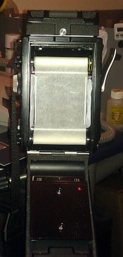
  1. The tracing paper screen I set up behind a perspex/plexiglass pressure plate (held in place with blu-tack). Paper and plate were all correctly dimensioned so they rest on the appropriate set of silver rails.
    IMAG0871_tracing_paper_under_perspex_for_C330f_focus_calibration.jpg
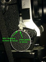
  2. Two pen marks on the focus knob showing an example of the two focal positions equating to a linear displacement of about 0.6mm. The mark at 11:58 o'clock is when the WLF screen is in focus, the one at 12:00 o'clock is when the film plane is in focus.
    IMAG0861_focus_knob_position_deviation_between_Mamiya_C330f_screen_and_film_plane.jpg
thanks
Peter
 

clayne

Member
Joined
Sep 4, 2008
Messages
2,764
Location
San Francisc
Format
Multi Format
Stupid question, but in all cases the focus cases under testing were all for straight-on subjects directly in the horizontal plane, right? I.e. no funky close-ups with aggressive angles, or things of that nature? What's the actual test subject?
 

PeterB

Member
Joined
Apr 3, 2005
Messages
644
Location
Sydney, Aust
Format
Medium Format
Stupid question, but in all cases the focus cases under testing were all for straight-on subjects directly in the horizontal plane, right? I.e. no funky close-ups with aggressive angles, or things of that nature? What's the actual test subject?

The test subjects vary and are basically whatever happens to be in my line of sight with a sharp line on them (if up close) like a window sill, the edge of a desk lamp, the brake cable of a bicycle, the characters/text of a system menu (i.e. sharp text) on the screen of Television set, a tree off in the distance. In all cases I focus on exactly the same point on the object when switching my view between between the WLF and the film plane (using a loupe).
 

clayne

Member
Joined
Sep 4, 2008
Messages
2,764
Location
San Francisc
Format
Multi Format
However, in those cases, you don't move/shift the body to have the taking lens be directly where the viewing lens once, was right? This will affect things if a. subject is up-close, and b. angle is not straight on, or c. subject is irregular in form.


|_\ .... <-- c330
|=|: ------------------------------ *
|=|: ----------------------------- ** <--- xmas tree / pile of cannon balls
.-- _____________________ ****______________________________

I'm throwing out this example above ^^.

However, seeing as you're already there with a loupe and are familiar with the focus of the film plane, this might be entirely too elementary and already discarded by you as a possibility. :smile:
 

PeterB

Member
Joined
Apr 3, 2005
Messages
644
Location
Sydney, Aust
Format
Medium Format
However, in those cases, you don't move/shift the body to have the taking lens be directly where the viewing lens once, was right?

Hi clayne. Thank you for pointing out this possibility. I don't reposition the camera body between focusing for the film plane and the viewing screen. During this testing I focus on exactly the same point in space on the object each time, so the scenario of focusing on two different cannon balls at different distances from the lens plane doesn't apply.

Ignoring temporarily the fact that my results are inconsistent, there is clearly more to aligning two lenses than I understood and the fact that half the time I establish focal discrepancies at close, medium and far distances is motivating me to do more research.

Through searching, I am discovering that calibrating the focus of a TLR is not necessarily an easy job, well I mean it doesn't seem to be documented fully in one place (except I assume in my camera's service manual which I really need to purchase for about $35 on eBay - yet by the time it arrives I probably would have solved the problem !!).
Up until now I haven't worried about ensuring the taking lens focuses properly at infinity. (see here , here and here). Some posts also indicate the distance scale needs to be correctly aligned. I don't even use my distance scale. I'm learning about backsighting, collimation etc. etc.
 

PeterB

Member
Joined
Apr 3, 2005
Messages
644
Location
Sydney, Aust
Format
Medium Format
Peter, I just posted on your photonet post regarding this. Your chrome shim looks like factory. The black one looks suspect, that is one thick a** shim! Something is amiss, I know the first thing I would do is do a test without that black shim. The spring lock being off by large amount still troubles me. Show a few shot where that was and how you fixed it.
Christiaan
The above quote is from (there was a url link here which no longer exists)as I am consolidating my cross posts to this thread.

Thanks Christiaan. I'll try removing the black shim on the viewing lens.

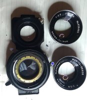
When I take the front element off the taking lens there is what looks like a brass shim screwed into the female thread of the remainder of the lens. Are you suggesting to remove or swap that to the viewing lens ?
IMAG0856_c330f_lens_set_80mm.jpg
Here is the small steel spacer I place under the spring to stop it wobbling back and forth by about 0.7mm
IMAG0874_C330f_spring_lensboard_retainer_spacer.jpg
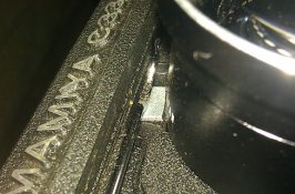
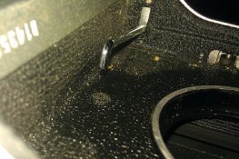
Here is the opposite end of the spring showing a small bump I noticed on the main body.
IMAG0879_C330f_spring_retainer_bump_on_body.jpg

When the lens plate is resting on the body and the spring is totally off I can rock the plate back and forth by a tiny amount, perhaps 0.2mm, so it seems pretty flat to me. Once the spring and my steel spacer is in place I can't rock it at all.
 

PeterB

Member
Joined
Apr 3, 2005
Messages
644
Location
Sydney, Aust
Format
Medium Format
Problem solved !

I think I've finally solved the problems causing a discrepancy between the viewing screen and film plane focus :happy:

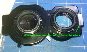
The top of the lens plate needed to be tilted away from the body so that the plate had no gap between it and the retaining spring. Previously I was pushing it flat against the body with a spacer btwn the spring and the plate, that was the wrong direction. The height of the spacer plus adhesive (black tack) is 0.6mm.

IMAG0895_C330f_lens_plate_showing_spacer_to_adjust_viewing_lens.jpg


I have confirmed that both lenses now focus together for distances of 0.6m, 3m and infinity.

Another way to give similar results would be to add another 0.6mm shim under the viewing lens. The current solution provides a tilt, while a lens shim would provide a planar offset. At least the solution I used also addresses my concurrent problem of the top retaining spring not touching the lens plate.

In response to Christiaan's suggestion to swap or remove the thicker shim, firstly it was not possible to swap them because they are keyed to fit each lens specifically using the position of the head of a very small screw. Secondly when I removed the 0.4mm shim from the viewing lens, it made the focus discrepancy worse. This is when I realised that I could fix the spring issue in the manner described above.
I thought I might have to adjust the focus of the front element of the taking lens at infinity with the distance scale set there too, but it now appears I don't have to.

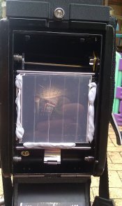
I suspect that the repeatability issue I had (making it harder to diagnose the real problem) was that the tracing paper I was using for a lens plane viewing screen wasn't taut enough at times since I was manually arming the shutter and not winding on the tracing paper to both tighten it and arm the shutter. To solve that problem I went back to using the following screen in the film gate comprising perspex sheet with some translucent tape on the lens side (e.g. Scotch magic tape).

IMAG0892_c330f_film_gate_makeshift_viewing_screen_of_perspex_and_Scotch_magic_tape.jpg

BTW speaking of non-flat film causing focus problems, check out the posts about film bulge here. (the word "bulge" should be highlighted)
 
Last edited by a moderator:

PeterB

Member
Joined
Apr 3, 2005
Messages
644
Location
Sydney, Aust
Format
Medium Format
I finally received the repair manual for the C330f. It only has two sections relating to adjustment of the focus. The first ensures the Lens Guide is parallel to the film plane, the second ensures the bellows extends the same distance when focusing through the viewing screen or at the film plane.
I'm attemting to follow the first section. refer to the page 7 attached.
Mamiya_C330f_Repair_manual_page_7.jpg

It isn't clear to me how to remove the focussing knobs or camera's side covers to adjust the guide plate at step 6-1.B.c and fig 18.

Can any C330f owners tell me how I can remove the knobs and side covers ?​
The service manual is light on details and doesn't even mention that.

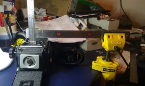
BTW instead of using a Dial Gauge, I opted for two steel rulers (see IMAG0917_Parallelism_of_C330f_Lens_Guide.jpg . The horizontally fixed one has been levelled and held in place with a vice. I tried using some vernier calipers rather than a 2nd steel ruler but for some reason I wasn't getting sufficiently repeatable results.

I also need to fabricate a small raised block to place the camera on (marked F-1 in figure 17). I think F-1 rests on the film rails. When the camera's door is open, the rear external edges of the body are not parallel with the front which is why the camera must be supported by the film rails resting on a special block.

thanks
Peter
 

PeterB

Member
Joined
Apr 3, 2005
Messages
644
Location
Sydney, Aust
Format
Medium Format
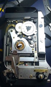
I realised that the exploded views in the rear of the manual are to be used to guide one in disassembling this camera. The leatherette side skins must be peeled off to reveal the first layer of screws. This is a shame as I will have to glue it back on again. Anyway at least I am making progress.
I also will find an Outside Calliper http://goo.gl/eYKx1 or large micrometer to measure the parallelism to save me locating a very flat block to rest the film gate on.
 

PeterB

Member
Joined
Apr 3, 2005
Messages
644
Location
Sydney, Aust
Format
Medium Format
I got one side panel off. Some screws are really hard to remove, so off to my local electronics store tomorrow to get a precision PH screwdriver with a fat handle so I can exert lots of torque. Tip needs to be hardened to prevent it shearing off like the cheap one did last night.

IMAG0933_C330f_LHS_with_cover_removed.jpg
 

PeterB

Member
Joined
Apr 3, 2005
Messages
644
Location
Sydney, Aust
Format
Medium Format
Camera front is NOT parallel to the film plane

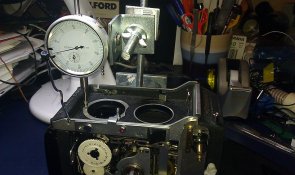
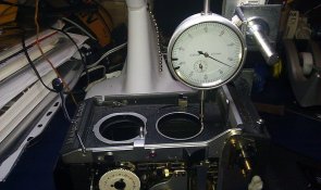
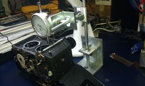
Update. I decided to purchase a dial gauge and make my own stand for it. Measurements with it confirmed that the front of the camera (when lenses removed) is NOT parallel to the film plane. The top of the viewing lens receptacle is 0.6mm closer to the film plane than the bottom of the taking lens receptacle. I placed a very flat block of wood 62mm x 62mm x (25+/-0.1)mm against the film gate touching the same rails the film would. This wood block then rested on the flat work table and mimicked the setup in the service manual above.

IMAG0935_C330f_viewing_lens_displacement.jpg IMAG0936_C330f_Taking_lens_diplacement_0.6mm_above_Viewing_lens.jpg IMAG0937_C330f_DIY_dial_gauge_stand.jpg

This narrowed the problem down to the camera body rather than the lens board/panel.

Now I have to continue trying to remove 3 stubborn screws as shown a few posts back in the relevant page of of the service manual I posted. I have already sheared the heads off two precision screw drivers, one supposedly made from Chrome Vanadium. I have since put some drops of penetrating oil around the screws to try and loosen them. I'm now using precision screwdrivers with hardened tips from Stanley.
 

Marc B.

Member
Joined
Oct 24, 2010
Messages
357
Location
USA, Pac/NW
Format
Multi Format
I think the OP needs a different focusing screen, or needs to shim the focusing screen.

Firstly, you're not attacking the problem by addressing/eliminating the simplest, or most common area that causes focusing problems, and that is usually the focusing screen..

Rack the lens board/bellows to get the taking lens in focus on the film plane, then shim the focusing screen for viewing lens focus.
If you haven't already lost shims from behind the front elements of the lens, put the lens back together and leave it alone.

You can use "Scotch Tape," spread across the film plane, (like lap-siding on a house), to imitate a ground glass for focusing the taking lens.
 

PeterB

Member
Joined
Apr 3, 2005
Messages
644
Location
Sydney, Aust
Format
Medium Format
I think the OP needs a different focusing screen, or needs to shim the focusing screen. Firstly, you're not attacking the problem by addressing/eliminating the simplest, or most common area that causes focusing problems, and that is usually the focusing screen.

Hi Marc, assuming your reply was directed to me, here are my thoughts.


The Mamiya C330f service manual contains only two sections pertaining to adjusting the focus.
  1. The first section seeks to ensure the front of the camera is parallel to the film plane.
  2. The second section ensures the distances travelled by the light rays (from taking lens to film and from viewing lens to view screen) are the same. It works off your assumption but instead of using shims for the focussing screen (as was the case with earlier models) it gets one to adjust the height of the screen by screwing up or down three posts in the camera.
Now I have proven that my camera has problem number 1. See photos of the dial gauge I posted yesterday in this thread for evidence. Why would I now try and solve that parallelism problem by moving the viewing screen up and down when the makers of the camera instruct us to solve it a different way ? (this way detailed (there was a url link here which no longer exists) from my post #35 in this thread)
 

clayne

Member
Joined
Sep 4, 2008
Messages
2,764
Location
San Francisc
Format
Multi Format
I'd say you're on the right track with where you're going. Any idea why the front "standard" is out of parallel? I have two c330s and never seen a consistent focus problem with either.

Perhaps a rack issue?
 

PeterB

Member
Joined
Apr 3, 2005
Messages
644
Location
Sydney, Aust
Format
Medium Format
Hi clayne. I'm not sure why the front is not parallel to the film plane. I bought it from the original owner a few years ago, I could always ask if they dropped it. At least the service manual tells me how to adjust i, but I am having a real problem getting those last 3 screws out to do the adjustment !
 

clayne

Member
Joined
Sep 4, 2008
Messages
2,764
Location
San Francisc
Format
Multi Format
Do they sell micro-sized impact screwdrivers? That's basically what you need - it's a big piece of metal + screwdriver bit that when you hit it with a hammer, it turns in a given direction and also pushes into the head of the screw. However, without going that far, I think the screws might be a bear because they were applied with thread-lock, most likely to combat vibration, etc. Check out something like this: http://www.radiocontrolzone.com/showthread.php?t=20290 and possibly search around more on how to loosen the thread-lock.
 

PeterB

Member
Joined
Apr 3, 2005
Messages
644
Location
Sydney, Aust
Format
Medium Format
Thanks Clayne. I have recently also read that heating the screw will melt and then loosen the threadlock. You've made me realise that penetrating oil is not going to work now ! I will get apply the tip of my soldering iron to the screw and hope that will do the trick. There isn't much nylon in the immediate area.
 

clayne

Member
Joined
Sep 4, 2008
Messages
2,764
Location
San Francisc
Format
Multi Format
Also, don't forget the trick with a screwdriver and a pair of vice-grips. If you can apply sufficient downward pressure to the head such that the screwdriver won't slip or otherwise strip the head, you can use vice-grips attached to the screwdriver body and counter-clockwise rotation to make use of the high mechanical advantage.
 

PeterB

Member
Joined
Apr 3, 2005
Messages
644
Location
Sydney, Aust
Format
Medium Format
Also, don't forget the trick with a screwdriver and a pair of vice-grips. If you can apply sufficient downward pressure to the head such that the screwdriver won't slip or otherwise strip the head, you can use vice-grips attached to the screwdriver body and counter-clockwise rotation to make use of the high mechanical advantage.

Tried that last night !! No success unfortunately. I bought some locking pliers just for that (since I didn't own any). I am getting close to deforming the phillips screw head right now, so I'm going to try the heating option as I'd rather not drill it out and tap a larger thread !
 

clayne

Member
Joined
Sep 4, 2008
Messages
2,764
Location
San Francisc
Format
Multi Format
Ah yeah, you definitely don't want to damage the screw head. Although, do be aware that if it comes to that you can drill just under the dimensions of the thread size and "crumble" the screw out without having to tap to a large size. But I'd imagine you would want to seriously avoid that solution in all cases...

I bet it's the thread lock.
 

PeterB

Member
Joined
Apr 3, 2005
Messages
644
Location
Sydney, Aust
Format
Medium Format
Another update. After 2 nights of struggles and more discoveries I've now come full circle.

In summary, the apex of each lens was always at the same distance from the film plane, so I will now proceed with adjusting the height of the viewing screen as per the repair manual. Hopefully this will solve the discrepancy of 0.6mm lineal adjustment in focus required when focusing using the viewing screen or a ground glass on the lens plane.

Details: I was unable to unscrew any of the 3 screws needed to make the front of the camera parallel with the film plane. I tried heating them with a soldering iron, then found the camera body is a superb metal heatsink so I moved on to a butane torch ! That didn't melt the threadlock so I opted for freezing spray to try and shrink the screw faster than the hole hoping it would crack the threadlock but to no avail !!

So then I decided to change tact. Rather than just measuring to the front of the camera body, I decided to measure to the apex of each front lens element (see attached pics.).
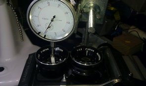
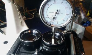
IMAG0940_C330f_80mm_viewing_lens_distance_to_apex_from_film_plane.jpg IMAG0941_C330f_80mm_taking_lens_distance_to_apex_from_film_plane.jpg


It then occurred to me that perhaps one of my lens shims was so thick because it was put in there to compensate for the camera front not being parallel.
To prove this I discarded my wooden slab and had a piece of plexiglass/perspex cut to support the camera on its film plane in a very steady fashion. Its dimensions were WxLxH=63x120x20mm
See pic.
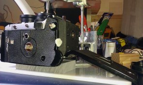
IMAG0943_C330f_film plane support is a 63mm wide perspex block.jpg


This gave me better repeatability in the measurements. I also bought a flat piece of thick off-cut perspex to rest everything on.

I then realised that by putting each shim back in place (a thick one for the viewing lens and a thin one for the taking lens) that when I measured to the apex of each lens' front element, they were nearly identical distances away from the film plane. In fact there was only a 0.03mm (=0.0012") difference !! Their apexes were aligned all along despite there being a 0.6mm fall across the entire camera front under the lens plate. As to whether using lens shims to solve this problem is an acceptable solution or not, I'm not sure. I say this because the lenses are still not perpendicular with the film plane (as the lens plate is parallel to the camera front but not parallel to the film plane). The lenses are just offset with shims so that their apexes are the same distance from the film plane. The lens axes are about 0.35 degrees tilted away from being perpendicular. I don't know how this affects critical focusing at any distances @f2.8. I suppose I could think about it some more and do the maths, but not right now.

I think what has happened is that in either a prior repair job or even when it was made in the factory, somebody decided to fix the anti-parallelism in this less than optimal manner.

Short of drilling out those screws I mentioned above the only other way I can think of to make the lens axes perpendicular with the film plane is to place a small shim between the front of the camera body and the lens plate at one end and re-shim the lenses.

Anyway, my next task is to adjust the viewing screen height to compensate for the 0.6mm lineal difference btwn it's light path and the film plane's light path.
 

PeterB

Member
Joined
Apr 3, 2005
Messages
644
Location
Sydney, Aust
Format
Medium Format
Yeah ! After much thought and adjustments I finally have everything parallel and perpendicular to within +/- 0.07mm and 0.05deg across the entire range of focus. (it was originally out by 0.6mm and o.35deg). I calculated that the depth of focus@f2.8 focused at infinity with the 80mm lens is about 0.25mm so this is well within acceptable limits.

Just to remind you, the problem I was trying to solve was that the front plane of the camera's body (with lenses removed) was not parallel to the film plane. The bottom was 0.6mm further out than the top. I think it was either dropped by its former owner or even assembled by a dodgy assembly line worker at Mamiya.

I decided to solve this problem by shimming the underside of the lens plate forward by 0.6mm and removing the thick 0.4mm shim on the viewing lens. This made the lens axes perpendicular with the film plane. The next step I took was to raise the 3 posts below the focussing screen by about 0.6mm (about 1.5 turns each). Now the image in the viewfinder focuses at the same point an image on the film plane does. At the film plane I placed 3mm perspex/plexiglass with scotch magic tape on the side facing the lens for a poor man's ground glass. I tested the focus tonight at about 4 different distances from 50cm to 20m.

Soon I'll run a test roll through of a tape measure and some fence pickets to be 100% certain !


I
 
Photrio.com contains affiliate links to products. We may receive a commission for purchases made through these links.
To read our full affiliate disclosure statement please click Here.

PHOTRIO PARTNERS EQUALLY FUNDING OUR COMMUNITY:


Ilford ADOX Freestyle Photographic Stearman Press Weldon Color Lab Blue Moon Camera & Machine
Top Bottom