LED Split Printing Enlarger Lamphouse

The Long Walk

H
The Long Walk

  • 1
  • 0
  • 73
Trellis in garden

H
Trellis in garden

  • 0
  • 0
  • 53
Giant Witness Tree

H
Giant Witness Tree

  • 0
  • 0
  • 55
at the mall

H
at the mall

  • Tel
  • May 1, 2025
  • 1
  • 0
  • 51
35mm 616 Portrait

A
35mm 616 Portrait

  • 6
  • 5
  • 188

Recent Classifieds

Forum statistics

Threads
197,502
Messages
2,760,237
Members
99,390
Latest member
mahakhumb
Recent bookmarks
0

radiant

Member
Joined
Aug 18, 2019
Messages
2,135
Location
Europe
Format
Hybrid
If I remember correctly the G70 has a condenser on one side and diffuser on the other, you can pull it out and reverse it to switch between condenser and diffuse enlarger. I had a G70 but I couldn't find any of the negative carriers so I switched to a M805 when one popped up in my area.

Yes, but I never understood how that supposed to work. And the manual is quite a stub, it doesn't go through all features - basically only the color printing part only. Maybe I need to take a better look / take photos and ask here for advice :smile:

Any ideas what enlarger could be most suitable for RGB strip type of conversion?
 

albada

Subscriber
Joined
Apr 10, 2008
Messages
2,171
Location
Escondido, C
Format
35mm RF
Any ideas what enlarger could be most suitable for RGB strip type of conversion?

Mal Paso discovered that you get uniform illumination by placing the LEDs in a circle around the top, and using a plastic diffuser at the bottom. I copied his design, and it works well. So I suspect that you can put strip(s) around the perimeter of the top of your light-head, and replace the condenser-lens at the bottom with a diffuser. If the top of the head is square or rectangular, then you can put 4 strips around the perimeter. If it's circular, then you will probably need to place each LED individually (not in strips), unless you don't mind having wrinkles in the strip to force it into a circle.

Mark Overton
 
Last edited:

koraks

Moderator
Moderator
Joined
Nov 29, 2018
Messages
20,840
Location
Europe
Format
Multi Format
So I suspect that you can put strip(s) around the perimeter of the top of your light-head, and replace the condenser-lens at the bottom with a diffuser.
This will most likely work perfectly.
With leds I found that as long as they're fairly closely spaced and you allow ca 4" of empty space between them and a piece of diffusing material ( I use milky white plexiglass), evenness is good. But it remains a matter of experimentation. Making some grade 5 prints for roughly 50% grey without a negative shows any unevenness quite clearly. Don't forget to stop down the lens by 2 stops or more, otherwise you'll just be evaluating light falloff of the lens.
 

radiant

Member
Joined
Aug 18, 2019
Messages
2,135
Location
Europe
Format
Hybrid
Great news guys, I will try with your advices when the strips arrive.
 

joan65_es

Member
Joined
Mar 20, 2008
Messages
5
Format
35mm RF
I am working on this, 5 meter rgb led strip in a kitchen container.
My ISO (R) values at the moment are:
00 = 180
0 = 157
1 = 135
2 = 120
3 = 100
The regulation is made with some PWM modules to regulate the speed in cc engines. I need to find the mixture for grades 4 and 5, for which I have planned
4 = 80
5 = 60
Oddly enough, it works
The enlarger is motorized and built at home
 

Attachments

  • 0.jpg
    0.jpg
    123 KB · Views: 179
  • Verd.jpg
    Verd.jpg
    138.5 KB · Views: 170

joan65_es

Member
Joined
Mar 20, 2008
Messages
5
Format
35mm RF
I have to clarify that this head is built for paper negatives and a maximum size of 4x5.
All he is designed for a 150mm lens.
 

Craig

Subscriber
Joined
Apr 8, 2004
Messages
2,241
Location
Calgary
Format
Multi Format
I'm looking to build an LED head for an 8x10 enlarger, would the circuit Mark Overton proposed work will using a conventional timer? I have one of the RH Designs F stop timers and I want to keep using that, but wasn't sure how it would work for controlling the buck blocks.

I understand the placement of the LED's, the thing that has puzzled me is contrast control and dimming.
 

Light Capture

Advertiser
Joined
Feb 5, 2008
Messages
204
Location
Ontario, Canada
Format
Multi Format
I replaced a lamp on Durst CLS 2000 head with 100W white led with reflector made from sheet metal and cooling from PC CPU. Print times were only bit slower than original 2000W lamp.
Quick test have shown that all contrast grades can be achieved with built in dichroic filters but didn't have chance to do rigorous testing and didn't try any color printing on it.
This could be feasible upgrade on dichroic and possibly on condenser enlargers. Not sure how well LED's work with contrast filters.

100W LED was ordered on eBay and exact specifications are not available, so I can't say if it's repeatable or if it would useable for color work.

If you have a dichroic head. It's very likely it will work well with this method for b&w printing. It can be tested with step wedge.
Step wedge doesn't have to be calibrated. Can be printed on transparent sheet or picture of printed step wedge can be taken and then negative can be used.
It would need series of small contrast test prints on every grade with both regular and LED source.
This way of testing can also confirm functionality if you make multicontrast head.

Best option would be looking at sensitivity graph for Ilford Multigrade papers and picking the right wavelength LED's to mimic what paper requires.
 

albada

Subscriber
Joined
Apr 10, 2008
Messages
2,171
Location
Escondido, C
Format
35mm RF
I'm looking to build an LED head for an 8x10 enlarger, would the circuit Mark Overton proposed work will using a conventional timer? I have one of the RH Designs F stop timers and I want to keep using that, but wasn't sure how it would work for controlling the buck blocks. I understand the placement of the LED's, the thing that has puzzled me is contrast control and dimming.

I used that circuit with a conventional timer, so yes, that arrangement will work. I connected the timer to the mains-input on the 24-volt power supply. The supply had rise- and fall-times that were short enough to be ignored.

Dimming can be done two ways, both using the same DIM wire on the Buck Block drivers:
1. Analog, ranging from 0 volts (off) to 10 volts (full power). You can connect a potentiometer to a resistor divider from the 24v to get this 0-to-10v range.
2. PWM. I used a 555 chip to generate that, which also worked well. A potentiometer let me set the duty-cycle.

My problems were that analog dimming would dim only by about 2.5 stops reliably, and I needed more. And when PWM was added, the Buck Blocks had some thermal drift, making light-level inaccurate.
I settled on using an Arduino microcontroller to generate PWM, and I replaced the Buck Blocks with Mean Well LDD-700 LED-drivers. Much better!
I don't know whether Buck Blocks are still available, but if not (or if they're costly), and you want to use them, I'll ship mine to you for free.

I love the results. LEDs run cool, I can set any contrast I want by changing green/blue ratio, and the diffuser hides small scratches and dust on negatives.

Mark Overton
 
OP
OP

Mal Paso

Member
Joined
Oct 14, 2019
Messages
365
Location
Carmel, Ca USA
Format
4x5 Format
I'm looking to build an LED head for an 8x10 enlarger, would the circuit Mark Overton proposed work will using a conventional timer? I have one of the RH Designs F stop timers and I want to keep using that, but wasn't sure how it would work for controlling the buck blocks.

I understand the placement of the LED's, the thing that has puzzled me is contrast control and dimming.

I have the power supply on and buck blocks powered and switch them with a conventional timer using a 120V 3 pole relay plugged into the timer outlet. One extra pole for white if I choose. I'm using 10 turn 20K pots and get 3.5 stops of power/contrast control. The system is fretless, no hard stops and works fine.
 

Craig

Subscriber
Joined
Apr 8, 2004
Messages
2,241
Location
Calgary
Format
Multi Format
Thanks for the replies, I'll look into the Mean Well drivers. I'llgo back and check the LED's I bought for their current requirements.
 

albada

Subscriber
Joined
Apr 10, 2008
Messages
2,171
Location
Escondido, C
Format
35mm RF
Blame @koraks 🙂. He pointed out that my LEDs should be driven at higher power in order to expose enlargements on slow papers in under a minute. Papers are most sensitive to blue, so red and green needed boosting. So I bought some Cree XE-G LEDs and installed them on my original lamp described in this posting, and updated my controller to double the power of red and green, changing from 0.7 amp to 1.4 amps. It works well, but the heatsink, which was a large piece of 1/16-inch thick sheet-metal, got hotter than I like. So I bought an aluminum plate that's six times as thick (3/8 inch), drilled and tapped holes, and moved the LEDs to that.
IMGP5389a.JPG


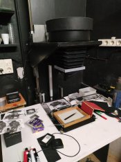
Installed on the enlarger:

IMGP5393a.JPG


Now the middle gets only slightly warm after running all LEDs at full power for 5 minutes.

This heatsink is overkill (too large). When all LEDs are at max, they consume 51 watts, producing perhaps 30 watts of heat. But I only had choices of 1-foot wide or 2-feet wide when selecting a plate from McMaster-Carr, so I choose 2 feet and cut it down to 20 inches wide. I could have cut it down more, but the weight is the same as the condenser assembly, so the weight is what the enlarger was designed for.

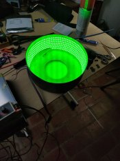
The LEDs emit ample light. This lamp can illuminate a 4x5 negative, and a 35mm frame uses only a small amount of that light (wasting the rest). Yet exposing a 35mm negative onto an 8x10, at f/8, takes only 11 seconds for FOMA RC paper. Ilford RC is only 7.5 seconds. Medium format will be much faster because the larger negative passes more light.

If you have a Beseler 45 enlarger, I encourage you to switch to LEDs. As you can see, it's easy to do with this type of enlarger. All you need to do is remove the lamphouse at the top, remove the condenser, put a circular diffuser at the bottom, put the LEDs on an aluminum plate, and attach the plate to the metal barrel that contained the condenser. That's the easy part. The hard part for most people will be building a controller (driver) for the LEDs. You'll see a couple of designs earlier in this thread.

For the record, here are the LEDs I'm using:

"Photo red", Cree XE-G, 660 nm, drops 2.6 v at 1.4 amp.​
"Green", Cree XE-G, 525 nm, drops 3.17 v at 1.4 amp.​
"Royal blue", Cree XT-E, 455 nm, drops 3.05 v at 0.7 amp.​

Royal blue is available in the new XE-G series, and I'd recommend that instead of the old XTE series.
 
OP
OP

Mal Paso

Member
Joined
Oct 14, 2019
Messages
365
Location
Carmel, Ca USA
Format
4x5 Format
Cool! I used thermal paste to bond heat sink fins to my array but you've got the surface area with just one piece of metal.
 

Pieter12

Member
Joined
Aug 20, 2017
Messages
7,516
Location
Magrathean's computer
Format
Super8
A note to those building their own LED light sources--the Heil unit sits right on top of the negative carrier, no condensers or mirrors involved, at least for Omega D enlargers. Like the photo in post #88.
 

koraks

Moderator
Moderator
Joined
Nov 29, 2018
Messages
20,840
Location
Europe
Format
Multi Format
This only works well if (1) the beam angle of the LEDs and their spacing are aligned with each other (2) there is sufficient distance between the light source and the negative carrier (3) the light source is of the same or larger surface area as the maximum negative size (4) the power output of the LED array is low enough not to create thermal issues. Those who DIY a LED head may not want to adhere to all of those requirements.
 

Pieter12

Member
Joined
Aug 20, 2017
Messages
7,516
Location
Magrathean's computer
Format
Super8
Has anyone tried just adapting a flush-mount LED ceiling fixture to an enlarger? If the output is even enough, seems like it might work.
Screen Shot 2022-11-01 at 1.49.06 PM.jpg
 

Steve Goldstein

Subscriber
Joined
Jul 8, 2007
Messages
1,738
Location
Northeastern US
Format
Multi Format
@albada: That's a very nice layout in post 88. I imagine that having the LEDs nearer the edge helps with overall light evenness.

What's the diameter of the circle on which you placed the LEDs? Did you also paint the interior of the mounting collar white? And where did you get them from already mounted on the ceramic carrier? My initial check of the cree-led.com site didn't show any LEDs mounted on that sort of ceramic.
 
Last edited:

albada

Subscriber
Joined
Apr 10, 2008
Messages
2,171
Location
Escondido, C
Format
35mm RF
I'll reply to the above responses and questions, but first I'll mention that I was dissatisfied with the eye-hazard and ungainly appearance of my lamp. So I cut off the corners:

IMGP5396a.JPG


That's better!
And my responses...

@Mal Paso : It's nice to hear from you! Your discovery that a circular arrangement of LEDs is sufficiently uniform still lives on!

@koraks : Another factor is the diffuser. It must be far enough away from the LEDs to provide enough uniformity. @Mal Paso found that putting the diffuser at the bottom of the condenser barrel and the LEDs at the top provided the necessary spacing. And your point (4) about thermal considerations is why I switched to the new thick aluminum plate. My original 1/16-inch thick sheet aluminum had too much thermal resistance.

@Pieter12 : Those flush-mount diffuse lights are tempting. They probably employ white LEDs, which would force the user to use contrast filters. The nice thing about separate color-control is that contrast can be controlled without filters.

@Steve Goldstein : The diameter I used is 136 mm, which is close to that of the barrel taken from the Beseler's condenser lamp.
The ceramic carrier you mention is actually aluminum for some, and copper for some. The carrier is called a "star", and you can buy LEDs mounted on stars from ledsupply.com and Cutter Electronics (in Australia). But the Cree XE-G series is new, so I was forced to buy the emitters (LEDs) and stars separately, and solder the emitters onto the stars myself. I bought the bare stars from Cutter and the emitters from digikey or mouser. To solder them, one starts by applying a little solder paste (not flux) to the tiny pads on the star.

IMGP5365a.JPG


I used the following DIY hot-plate to solder them on:

IMGP5370a.JPG


Using tweezers, I placed the star on the hot chunk of aluminum, waited 5 seconds after the paste melted into solder, and then put the star on the sponge soaked with water to cool it. This technique works well for one component, but I'd be reluctant to try it on a typical circuit board. My thumb in the next picture shows how small these emitters are.

IMGP5366a.JPG


Notice that each star above has some solder on one of the four large wire-connector pads. When I saw that paste turn into solder, I began counting the 5 seconds. I expect ledsupply.com to someday stock Cree XE-G emitters mounted on stars, and then the hassle with DIY hot-plate above won't be necessary.
 

koraks

Moderator
Moderator
Joined
Nov 29, 2018
Messages
20,840
Location
Europe
Format
Multi Format
Using tweezers, I placed the star on the hot chunk of aluminum, waited 5 seconds after the paste melted into solder, and then put the star on the sponge soaked with water to cool it. This technique works well for one component, but I'd be reluctant to try it on a typical circuit board.

Oh, it'll work for larger PCB's / more components as well, but I'd recommend doing it in the regular order: apply solder paste to the pads, then mount the components (they'll stick to the paste quite well) and then put the whole thing onto the makeshift hot plate until all the paste has molten and all components have settled. Take it off and let cool gradually. Rapid cooling is not really necessary and might even induce thermal cracking, so it's usually recommended to just allow the assembly to cool down slowly (I never noticed any problems with rapid cooling under a running tap though).

@Pieter12 : Those flush-mount diffuse lights are tempting.

They are! Despite my often critical comments, I really like easy, straightforward solutions. But I also find that they often aren't as straightforward as they might seem. For instance, as @Pieter12 also remarks, the question is how even the diffusion actually is on those. My experience with ceiling lights like these (not for enlargers, but for their intended purpose) is that the diffusion isn't particularly good; there's usually a large hot spot - or several, depending on the actual light source. It's a matter of experimenting; these units are often not very expensive, so why not give it a try? Secondary issues would be to mount the thing onto an enlarger, blocking out any stray light etc. When all's said and done, you might end up modifying the store bought item so much that you might have been better off just getting a sheet of milky plexiglass or frosted glass and a LED bulb of your choice.
 

Kilgallb

Subscriber
Joined
Oct 14, 2005
Messages
805
Location
Calgary AB C
Format
4x5 Format
Has anyone tried just adapting a flush-mount LED ceiling fixture to an enlarger? If the output is even enough, seems like it might work.
View attachment 320555

I did just that.

I have attached pictures of the mod and parts. I removed the ring on the bottom of the Beseler 45 Dichroic boxx, the part that mates with the enlarger. I removed the lid frm the mix chamber and mounted the lamp on top. So I am still using the beseler diffuser. Total cost so far is $30 Canadian for the lamp. I will invest a bit more to make it a permanent installation.


albada

Subscriber
Joined
Apr 10, 2008
Messages
2,171
Location
Escondido, C
Format
35mm RF
I did just that.

I have attached pictures of the mod and parts. I removed the ring on the bottom of the Beseler 45 Dichroic boxx, the part that mates with the enlarger. I removed the lid frm the mix chamber and mounted the lamp on top. So I am still using the beseler diffuser. Total cost so far is $30 Canadian for the lamp. I will invest a bit more to make it a permanent installation.

Your idea is both elegant and inexpensive. Here's a possible improvement at no additional cost: You mentioned that you're still using the Beseler diffuser. The LED lamp also contains a diffuser, so that's two diffusers, both reducing light. You might try removing the diffuser on the lamp. That will give you more light, making focusing easier and helping 35mm which needs all the light it can get due to the small neg size.
 
OP
OP

Mal Paso

Member
Joined
Oct 14, 2019
Messages
365
Location
Carmel, Ca USA
Format
4x5 Format
Your idea is both elegant and inexpensive. Here's a possible improvement at no additional cost: You mentioned that you're still using the Beseler diffuser. The LED lamp also contains a diffuser, so that's two diffusers, both reducing light. You might try removing the diffuser on the lamp. That will give you more light, making focusing easier and helping 35mm which needs all the light it can get due to the small neg size.

On those fixtures the LEDs use the light piping effect of the glass to distribute the light. The one I'm familiar with, the LEDs are under the rim and shine light into the edge of the glass. Others may be different but you may destroy the fixture finding out or find the LEDs bonded to the glass. Not a big expense but something to note.
 

albada

Subscriber
Joined
Apr 10, 2008
Messages
2,171
Location
Escondido, C
Format
35mm RF
On those fixtures the LEDs use the light piping effect of the glass to distribute the light. The one I'm familiar with, the LEDs are under the rim and shine light into the edge of the glass. Others may be different but you may destroy the fixture finding out or find the LEDs bonded to the glass. Not a big expense but something to note.

Thanks for pointing that out. I (probably) wrongly assumed it was a diffuser. I wrote software that controlled the LEDs that supplied the one-dimensional light pipes (at least I think that's what they are called) which illuminated the paper under the moving scanner-bar in HP all-in-one printers. It didn't occur to me that these fixtures would use them, although it makes sense to do so -- light pipes are cheap and more efficient than diffusers.
 

albada

Subscriber
Joined
Apr 10, 2008
Messages
2,171
Location
Escondido, C
Format
35mm RF
Oh, it'll work for larger PCB's / more components as well, but I'd recommend doing it in the regular order: apply solder paste to the pads, then mount the components (they'll stick to the paste quite well) and then put the whole thing onto the makeshift hot plate until all the paste has molten and all components have settled. Take it off and let cool gradually. Rapid cooling is not really necessary and might even induce thermal cracking, so it's usually recommended to just allow the assembly to cool down slowly (I never noticed any problems with rapid cooling under a running tap though).

@koraks is correct. I tried the opposite order of melting the solder first and then placing the LED on it with tweezers. That failed. So I used @koraks order for all the LEDs. For the benefit of anyone who wishes to try soldering such SMD (=Surface Mount Device) components, here is more detail on the materials and method I used. I don't claim this is ideal, but it worked for these LEDs.
  • The paste was CHIPQUIK SMDLTLFP, which Mouser describes as "lo temp solder paste", part number 910-SMDLTLFP. "Lo temp" means the reflow profile (i.e., recommended temperature-vs-time curve) peaks at 165 C. Other reflow profiles I've seen peak at 230-250 C, so this solder melts at a lower temperature. I like that because I hate heating electronic components.
  • I applied as little paste as possible so that the resulting solder joint would be thin, in order to (1) minimise its thermal resistance, and (2) not create bridges. A bridge is created by solder spreading across two pads, shorting them together. The pads on these SMD parts are tiny, so I suspect there is a high chance of bridging if paste is applied generously.
  • I placed the LED onto the pasted pads with tweezers. I noticed that a LED would not drift into its correct position accurately enough when heated, so I first positioned the LED to be accurately centred horizontally. I positioned it vertically so that no portion of pad was visible above or below. This accuracy is around +/- 0.1 mm (!), and to get that, I would nudge the LED by placing a thin jeweler's screwdriver by it, and then leaning the screwdriver over at an angle, touching the LED and shifting it slightly. Such work requires patience and close-up glasses.
  • To get the temperature of the DIY hot-plate somewhat close to correct, I set the stove to its lowest setting, waited for the temperature of the aluminum block to stabilise, and placed a blank star on it with a blob of paste on a large pad. It did not melt. So I boosted the stove's temperature slightly, and it melted in 6 seconds. That's good enough. I soldered all LEDs at that temperature.
I've watched SMD soldering videos on youtube, and am surprised at much paste folks use. Some videos even show you how to remove the resulting bridges. I regard that as sloppy. I'd rather apply paste sparingly to start with. Furthermore, bridges under these LEDs and similar chips cannot be removed. Instead, you must de-solder the chip and try again. Apply paste sparingly.
 
Photrio.com contains affiliate links to products. We may receive a commission for purchases made through these links.
To read our full affiliate disclosure statement please click Here.

PHOTRIO PARTNERS EQUALLY FUNDING OUR COMMUNITY:


Ilford ADOX Freestyle Photographic Stearman Press Weldon Color Lab Blue Moon Camera & Machine
Top Bottom