LED RGB Additive Enlarger Head - Building One?

Brentwood Kebab!

A
Brentwood Kebab!

  • 0
  • 0
  • 9
Summer Lady

A
Summer Lady

  • 0
  • 0
  • 9
DINO Acting Up !

A
DINO Acting Up !

  • 0
  • 0
  • 8
What Have They Seen?

A
What Have They Seen?

  • 0
  • 0
  • 13
Lady With Attitude !

A
Lady With Attitude !

  • 0
  • 0
  • 13

Recent Classifieds

Forum statistics

Threads
198,755
Messages
2,780,468
Members
99,698
Latest member
Fedia
Recent bookmarks
0

polyglot

Member
Joined
Jun 12, 2009
Messages
3,467
Location
South Australia
Format
Medium Format
While I'm not convinced 8 bits is enough control, you can get as much as you want from an Arduino because you don't need to use the built-in PWM channels. The PWM frequency need not be high so you can do it in software to as much resolution as you want.

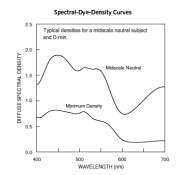
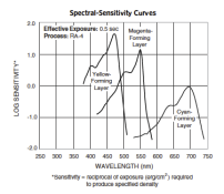
The greater problem IMHO is the C41/RA4 pair was designed with continuous spectrum in mind and using some very non-optimal dye technologies with overlaps, couplers, restraining couplers, etc. You're trying to print with just 3 points in the spectrum, which means your paper will not see all the subtleties of dye interactions (absorption spectra in the neg vs sensitivity spectra in the paper) that it is meant to. To make it worse, most media have more than 3 different dyes, e.g. most Fuji products have at least two green-sensitive dyes in the film and I presume that they are coupled to two subtly different absorption dyes.
 

Photo Engineer

Subscriber
Joined
Apr 19, 2005
Messages
29,018
Location
Rochester, NY
Format
Multi Format
Nowdays, the C41/RA4 pair is more tolerant of this type of spectrum due to the use of laser printers which have a really discontinuous spectrum.

PE
 

polyglot

Member
Joined
Jun 12, 2009
Messages
3,467
Location
South Australia
Format
Medium Format
True, the paper can handle a discontinuous spectrum handily, i.e. it has only 3 dyes. But lightjets involve significant digital pre-processing in order to obtain appropriate colour quality, i.e. they are carefully calibrated devices.

Exposing a negative through a spiky spectrum is different. I'm pretty sure you could calibrate it well enough to achieve a neutral step wedge (maybe some unavoidable crossover from the designed-for-digital paper), but I would expect to see increased delta-E issues, particularly in secondary colours where there are multiple interacting dye layers being activated in the negative.

Think of it as a tri-colour LED having the ultimate in really low CRI. If our eyes can perceive CRI issues then I expect that the paper probably can too, unless you know for sure that the LED wavelengths each match exactly to a single dye layer in the negative.
 
OP
OP
L Gebhardt

L Gebhardt

Member
Joined
Jun 27, 2003
Messages
2,363
Location
NH
Format
Large Format
Does anyone know how the color bands in most C41 film are setup? Do the peaks in the film line up with the peaks in the papers? How wide are they? Is there overlap between the dyes? It really is the critical piece to choosing the LEDs. I haven't been able to find any plots of these.
 
OP
OP
L Gebhardt

L Gebhardt

Member
Joined
Jun 27, 2003
Messages
2,363
Location
NH
Format
Large Format
Thanks, I didn't recognize that chart as being what I was looking for. Makes sense now that I see it. I am surprised at how non peaky it is in the blue to green area. It's also interesting that the peaks for the film don't really line up with the paper. Seems to me that we should pick the LEDs to match the film, and not the paper. That's how a continuous spectrum source would look to the paper. Does that sound right?

If the above is correct I think the Royal Blue, Green and Red Cree XPE LEDs would work pretty well. The red is the one that's farthest off, but that also looks to be the least critical since it has the least chance at cross contamination. And it has the bonus of being fully compatible with my current head for VC paper.
 

E76

Member
Joined
Mar 20, 2008
Messages
401
Location
Baltimore, MD
Format
Medium Format
I would suggest taking a look at the Kodak Wratten tricolor filter spectra, and matching your RGB sources to them as closely as possible. You can then use the Wratten gels as LED trimming filters to get almost an exact match. IMHO, this will hopefully minimize your frustration as you will be working with a known source as far as the paper is concerned. Additionally, you'll be able to take advantage of at least some of the data Kodak has published in the data sheets regarding tri-color exposure.
 

Photo Engineer

Subscriber
Joined
Apr 19, 2005
Messages
29,018
Location
Rochester, NY
Format
Multi Format
The films and paper sensitivities line up more than you think. In fact the curve shape (characteristic curve) and the sensitivities of the paper are aligned to give "perfect" prints.

PE
 

Athiril

Subscriber
Joined
Feb 6, 2009
Messages
3,062
Location
Tokyo
Format
Medium Format
Not sure if mentioned yet.

Just build an array of R, G, and B LEDs. All you'll need is 3 PWM (pulse width modulator) circuits to dim each R, G, B component without altering their colour (it just turns them on and off really fast, rather than altering voltage and current).

Rather than trying trial and error on paper, get/borrow a meter that shows spectral distribution. Take readings at different settings of a colour dichroic head.

You will then have a basis to mark positions on the PWM setting knobs that correspond to traditional filtration values.


Getting a good spectrum is only difficult with single white LEDs (or array of the same one).

You can go the dichroic method if its an existing enlarger needing a bulb replacement, but you should mix different white LEDs not just one type and from one source etc.
 
Last edited by a moderator:
OP
OP
L Gebhardt

L Gebhardt

Member
Joined
Jun 27, 2003
Messages
2,363
Location
NH
Format
Large Format
The films and paper sensitivities line up more than you think. In fact the curve shape (characteristic curve) and the sensitivities of the paper are aligned to give "perfect" prints.

PE

I've attached the Spectral Dye Density curves for Portra 400 and the Spectral Sensitivity curves for Endura.

I'm probably reading things wrong, but the dye peaks for the film look to be about 450nm, 520-540nm, and 690nm. Where as the paper looks to be most sensitive at 475nm, 550nm and 695nm.

They are obviously close, but I would have thought they would be a bit closer. As far as choosing the correct LEDs goes, it looks to me that getting 450nm Royal Blue would be better than a 475 Blue, simply because it will have less overlap with the green (maybe allowing better blue/green separation in the prints). The green choice seems to be fixed around 530nm, and the red around 625 (which seems too low to be ideal, but upping the brightness should allow it to expose the cyan forming layer).
 

Attachments

  • Portra 400 Spectral Dye Density.png
    Portra 400 Spectral Dye Density.png
    23.5 KB · Views: 116
  • Endura Spectral Sensitivity.png
    Endura Spectral Sensitivity.png
    31.4 KB · Views: 115
OP
OP
L Gebhardt

L Gebhardt

Member
Joined
Jun 27, 2003
Messages
2,363
Location
NH
Format
Large Format
Not sure if mentioned yet.

Just build an array of R, G, and B LEDs. All you'll need is 3 PWM (pulse width modulator) circuits to dim each R, G, B component without altering their colour (it just turns them on and off really fast, rather than altering voltage and current).

Rather than trying trial and error on paper, get/borrow a meter that shows spectral distribution. Take readings at different settings of a colour dichroic head.

You will then have a basis to mark positions on the PWM setting knobs that correspond to traditional filtration values.


Getting a good spectrum is only difficult with single white LEDs (or array of the same one).

You can go the dichroic method if its an existing enlarger needing a bulb replacement, but you should mix different white LEDs not just one type and from one source etc.

For the VC head I use PWM to control the current level from a BuckBlock dim-able constant current driver. This allows for a simple circuit on the Arduino. I figure with some readings from a color analyzer I could develop an exact map of intensity in CC units from a base vs power. If that doesn't allow smooth steps in density I may need to design my own PWM circuit as you suggest, or handle the PWM in software as Polyglot suggests.

I guess I should just get a few of the LEDs and experiment at this point.
 

David Grenet

Member
Joined
Jan 29, 2007
Messages
309
Location
Sydney, Aust
Format
Multi Format
650 nm red LEDs do exist, although they seem to be less common. If I were doing this (and I may in the future when I have more time) I would hunt down the filters normally used in additive printing and look at their transmission spectra.
 

DREW WILEY

Member
Joined
Jul 14, 2011
Messages
13,928
Format
8x10 Format
There are still some basic misconceptions floating around this thread, and I only have limited time to post today. But let me first respond to Ron and state
that sophisticated simultaneous additive colorheads are even easier to batch balance per film or paper than ordinary subtractive ones. If fact, Durst was already converting all their industrial colorheads to additive - and I have seen these and handled the components - but then pulled the plug on the entire
commercial line of enlargers (the current 4x5 unit is nice, but was never classified as part of that division). None of them ever reached the commercial
market, though I have a hunch where the balance of them ended up in use. I did not use the Durst model myself due to the potential heat issues (which
was also the achilles heel of the ZBE starlight series - and they too wanted to make an additive unit but were having issues already - that was back when
a lot of candlepower was needed for Ciba printing). ... But the reason I'm a little hesitant to make casual recommendations about nanometer bandwidth
tolerances is that you really do need to study this in depth some more. The interaction of color neg film and the paper itself is relatively complex, and you
don't want to end up with a colorhead which limits your use of either. So you pretty much have to figure out how much of the dye peaks you want to
keep, and how much to cleanly separate. I personally make a family of ideally exposed sheets of film of all the relevant color neg and transparency films
which are representative (using a Macbeath Chart under tightly controlled color temp conditions) and establish my operative parameters with any given
paper. But to cut to the chase, the actual results with my own additive colorheads are even better than with Lightjet etc. The hues of every type of color
film come out more accurately than with subtractive colorheads, and there is even less work arriving at this (tweaks for personal esthetic considerations
or exposure errors in the first place have to be done afterwards regardless)... there is no white light residual cross-contamination as in subtractive;
but neither do you want your bandwidth so narrow that it isn't versatile. ... I won't go into the electronics debate at the moment, but am merely
stating how I do this all the time and know how it works in principle. ... you can really get nice results if you come up with a good additive system.
 

Photo Engineer

Subscriber
Joined
Apr 19, 2005
Messages
29,018
Location
Rochester, NY
Format
Multi Format
I've attached the Spectral Dye Density curves for Portra 400 and the Spectral Sensitivity curves for Endura.

I'm probably reading things wrong, but the dye peaks for the film look to be about 450nm, 520-540nm, and 690nm. Where as the paper looks to be most sensitive at 475nm, 550nm and 695nm.

They are obviously close, but I would have thought they would be a bit closer. As far as choosing the correct LEDs goes, it looks to me that getting 450nm Royal Blue would be better than a 475 Blue, simply because it will have less overlap with the green (maybe allowing better blue/green separation in the prints). The green choice seems to be fixed around 530nm, and the red around 625 (which seems too low to be ideal, but upping the brightness should allow it to expose the cyan forming layer).

First, you subtract the color mask density from the dye density and then you subtract the 50M and 50Y CC filter densities from the color paper. This will give you what the paper "sees" when it "looks" at the film. This assumes white light printing. Once you do that, the spectra look quite different.

So, just looking at those curves can be misleading. Particularly since they are on drastically different scales for the wavelength. The paper curves also do not show the blue sensitivity of the R and G layers which further alters that data.

PE
 

DREW WILEY

Member
Joined
Jul 14, 2011
Messages
13,928
Format
8x10 Format
Your peak aim points are always 450,550, and 650. Then you figure out how much latitude you need to each side in order to accommodate your LED sources in reference to a variety of films. It's easier to visualize all this with chromes, since with negs you do have to interpret the
graphs with that orange mask in place, and in the case of Fuji paper, with a blue overlayer. With my own additive heads I ran a very thorough
series of tests then plotted each respective channel with a densitometer. Basically, I ran each channel of RGB separately at full purity, and
plotted this using a step tablet and TMX film, then I did it using full white light only, but projected thru hard conventional 29,61, and 47B sep
filters mounted over the lens. Then I ran and plotted a combination of the two, using dedicated colorhead channels PLUS the glass sep
filters over the lens. All three sets of results came out identical. (And of course, there is no density issue using a deep filter when the matching light color is identical). This amounted to a lot of work; but it demonstrated that the color characteristics of my colorhead are essentially ideal. An overkill project per color printing itself - but I was running these test in relation to making color sep neg for dye transfer
printing, which need to be fairly precise. ... I ended up with a lot better than "fairly" precise.
 

DREW WILEY

Member
Joined
Jul 14, 2011
Messages
13,928
Format
8x10 Format
E76 - Wratten filters wouldn't work as trimmers for several reasons. First, we're talking about simultaneous printing, not successive. They'd
fade quickly and be expensive to constantly replace, and would affect image sharpness because you'd have to use them over the lens. There
are several other reasons. If the LED is somewhat off peak sensitivity, a trimmer will act as ND or worse, truncate the correct target. That's
why you need to have LED's of very close specifications. This is not like halogen where you can select a slice of a continuous spectrum.
 

Photo Engineer

Subscriber
Joined
Apr 19, 2005
Messages
29,018
Location
Rochester, NY
Format
Multi Format
If you look at the color paper, you will see peak sensitivity at 700 nm, and you will see a "hole" to the left which is where the WR13 allows passage of light for the use of a safelight. These two facts are not accidental!

PE
 
OP
OP
L Gebhardt

L Gebhardt

Member
Joined
Jun 27, 2003
Messages
2,363
Location
NH
Format
Large Format
First, you subtract the color mask density from the dye density and then you subtract the 50M and 50Y CC filter densities from the color paper. This will give you what the paper "sees" when it "looks" at the film. This assumes white light printing. Once you do that, the spectra look quite different.

So, just looking at those curves can be misleading. Particularly since they are on drastically different scales for the wavelength. The paper curves also do not show the blue sensitivity of the R and G layers which further alters that data.

PE

I had forgotten about the orange mask. It makes sense now is adding into making the curves look lumpier than than I expected. I am guessing the orange mask is what is showing up on the minimum density plot and needs to be subtracted from the midscale neutral plot.

Wouldn't subtracting out the 50M and 50Y from the paper be superfluous? I thought the initial filter pack was there to remove the orange mask. Or is there an additional mask density for the paper too?
 

Photo Engineer

Subscriber
Joined
Apr 19, 2005
Messages
29,018
Location
Rochester, NY
Format
Multi Format
The paper wedge spectrogram is "doctored" to eliminate the blue sensitivity of the red and green layers. If you actually saw this in color, the bottom of the yellow would be almost black.

By adding the CC filters, the curves are modified and the speeds of the B and G are decreased. This results in equal speed in all layers and so the heights of the curves are equal. As it is, the blue has an ISO speed of nearly 100 while the red is only about 25. When done, the paper is about 25 due to the mask and the filter pack.

See my other post on peak sensitivity of the layers.

PE
 

DREW WILEY

Member
Joined
Jul 14, 2011
Messages
13,928
Format
8x10 Format
Larry - you can get entire textbooks on this kind of thing, like from Edmund Optical industrial division. I also had voluminous data bases sent to me from
OCLI, along with direct engineer contact, back when they were the largest coating lab in the world. You could find out the same stuff from Hoya industrial
division or any number of other sources. I also have the old full Wratten catalog from Kodak with all their conventional filter spectrograms. The problem will
be in acquiring true spectrograms for any hypothetical LED source. The correct way to design a trimmer filter is that you have to calculate the angle of
indidence and operating temp of your bulb and its dedicated reflector. Then you need a different pair of filter for each of the R,G,and B components.
These act like a sandwich and cut off the wavelength selectively on either side of the engineering value. This is much more effective than forcing the light
through a hard separation filter. Otherwise, the bulbs themselves have to hit fairly close to ideal. My argument here - and it has certainly worked in the
real world of printing for me - is that you want to design a versatile colorhead that won't hit speed bumps with a minor change in materials. I'm not going
to argue with Ron on those subjects he knows far better than I, but if it were me, I'd forget about things like safelight holes, work in total darkness, and
build a colorhead which works with virtually any combination of chrome or neg and compatible paper. When Durst designed their own additive heads, they
essentially built a closed-loop system utilizing dichroic hard separation filters passing the hypothetical ideal values which I already noted. My own colorhead
design works more on the sandwich principe, and has several other design features which I feel are a strong improvement over the Durst, but involve
integrating multiple light sources. But it doesn't matter whether I use Kodak paper or Fuji, Ektar or Portra, or even chrome film and Cibachrome. It works
splendidly with all of these. I can also use this for very precise dupe and color interneg work, or extremely precise color separation work. But if you are
going LED you are going to be a bit of a pioneer and will have some of your own learning curve.
 

EdSawyer

Member
Joined
Sep 3, 2008
Messages
1,793
Format
Multi Format
Wow, some good info in this thread. I am impressed with the depth of knowledge from all parties.

Larry, I am in Dover. Drew is right, the large-print capability of the minolta/beseler is probably not great - I haven't tried really huge prints yet, but it's ok up to 16x20 or so at least. They are less obnoxious than strobes like you would use to take a picture. Many multiple high-frequency/low-intensity flash firings, makes for almost continuous light in a way. It's not too bad from an annoyance standpoint.

color printing with this system is easy - additive is more "logical" than subtractive. The head controller can be used either way, but basically if you need it more red in the print, you add more red. Density can be changed independently. Density and color can be changed in 1-cc increments from 0-255. There's a small probe that can be used to sample different areas of the negative at the easel, and you can do sophisticated averaging across multiple points, etc. The analyzer itself is quite impressive, allows automated color ring-arounds, etc. Pretty expensive in its day but uber-cheap nowadays on ebay.

I used one professionally as a photojournalist years ago and liked it, so standardized on it for home use when I set up my current darkroom.

-Ed

Ed, where in NH are you located? I've heard mixed reviews of pulsed heads. It sounds like it would give me a head ache in short order, but maybe they don't behave like strobes. So how easy do you find color printing with this system? Does it take any mental contortions (more than normal) to dial in the color?
 

E76

Member
Joined
Mar 20, 2008
Messages
401
Location
Baltimore, MD
Format
Medium Format
E76 - Wratten filters wouldn't work as trimmers for several reasons. First, we're talking about simultaneous printing, not successive. They'd
fade quickly and be expensive to constantly replace, and would affect image sharpness because you'd have to use them over the lens. There
are several other reasons. If the LED is somewhat off peak sensitivity, a trimmer will act as ND or worse, truncate the correct target. That's
why you need to have LED's of very close specifications. This is not like halogen where you can select a slice of a continuous spectrum.

Ideally the filters would be placed in front of the LEDs, not the lens. You're right about off-peak wavelengths, which is why I said you'd have to still match the LED response to the filters. Using the Wratten filters as trimmers would let you use a wider band LED, while still maintaining the ideal spectral power distribution.
 

DREW WILEY

Member
Joined
Jul 14, 2011
Messages
13,928
Format
8x10 Format
Wrattens were never used in such as fashion in conventional enlargers simply because they'd catch fire in no time flat! I've seen a few
jerryrigged subtractive heads where they were used at a comfortable distance, but then they fade easily anyway. I don't know if LED's run cool enough or low-UV enough to make this feasible. One can also acquire tougher polyester filters, but I'd still be skeptical. The way to go on the long haul would be with dichroics, but then you have to factor in the angle of incidence relative to the focal point of the bulb. I don't know if LED's ever have a burn-pistion issues like halogens - probably not. Of course, a relatively cheap set of Lee poly filters could be used in an optical bench prototype mockup to save money on the final project.
 

DREW WILEY

Member
Joined
Jul 14, 2011
Messages
13,928
Format
8x10 Format
... (interrupted)... where I do use specialized Wrattens supplementary to my own additive colorheads is in things like interneg work from chromes. Since this is generally done film to film in a registered contact frame, filters placed over the enlarger lens as a light source as no
problem. In certain cases it is easier to do things this way than go back a retest everything for an in-colorhead only correction. Another example is when I want to make a precise neutral silver mask for tweaking a color neg, I will simply take a voided, processed sheet of the
film to act as my null filter for the integral orange mask, plus whatever I think I need to correct the pan film to the colorhead settings (pan film generally having slightly depressed green sensitivity, but the specifics vary since I employ both FP4 and TMY for these applications. True gel Wrattens aren't cheap anymore, but I've found them more accurate than the Lee substitutes.
 
Photrio.com contains affiliate links to products. We may receive a commission for purchases made through these links.
To read our full affiliate disclosure statement please click Here.

PHOTRIO PARTNERS EQUALLY FUNDING OUR COMMUNITY:


Ilford ADOX Freestyle Photographic Stearman Press Weldon Color Lab Blue Moon Camera & Machine
Top Bottom