

I already have a UV exposure unit made from UV tubes that I use for alt. process prints as well as PCB's. Because I was waiting for components for another project so I had some 'dead time', and I also had some parts in the parts bin that I thought I could put to good use, I did a quick and dirty min UV exposure box. It's essentially a 10W UV COB led with the necessary parts around it to make it work stand-alone. Its primary purpose is really to expose PCB's for my DIY projects, but it should also work fine for smallish alt-process prints; I think anything up to 5x7" would print within an acceptable amount of time.
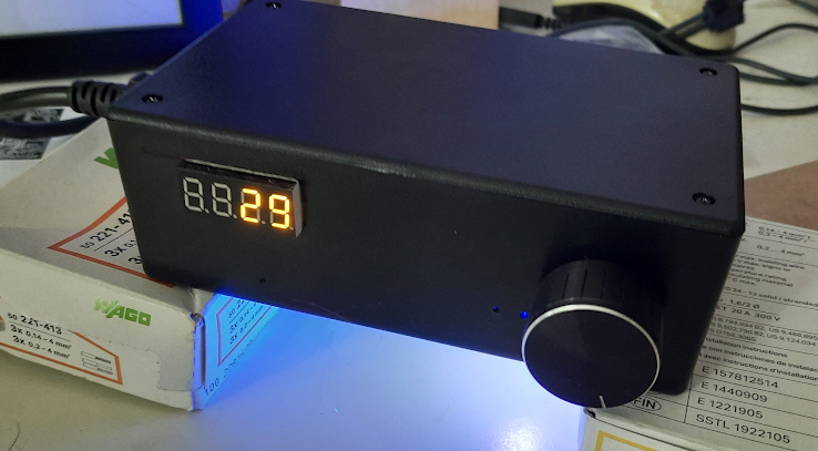
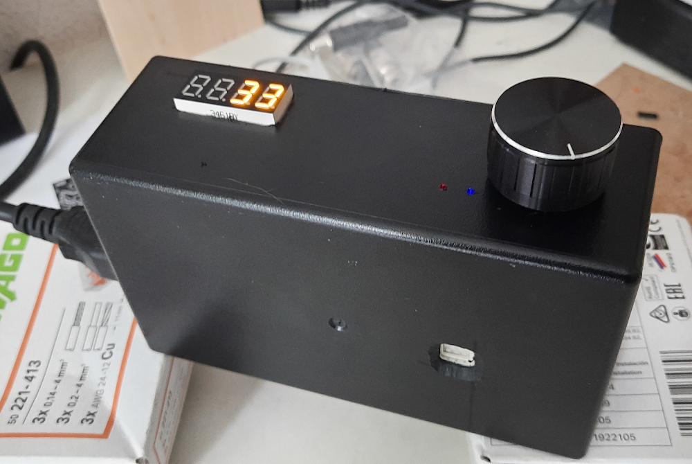
Excuse the abysmal cameraphone pics. Just to get an impression of the finished contraption.
The main reason for making this is to see if the quasi-point source of a COB LED would give a noticeable resolution advantage over the large bank of UV-B tubes I've been using so far. Not really of of necessity, since the UV-tube source actually works fine as it is, but just...you know, because I can.
It's not going to win any beauty contests in any department - mechanical construction, electronics design or software engineering. It's all done very quick & dirty, but it seems to work. Haven't tested it yet for its intended application, but all seems fine so far. I have in mind to mount it underneath a shelf above my workbench with a couple of brackets so it's conveniently out of the way when I don't need it, but close at hand whenever I do. So that's why the LED output is actually at the bottom of the box as you can see further down this post.
Here's the schematic:
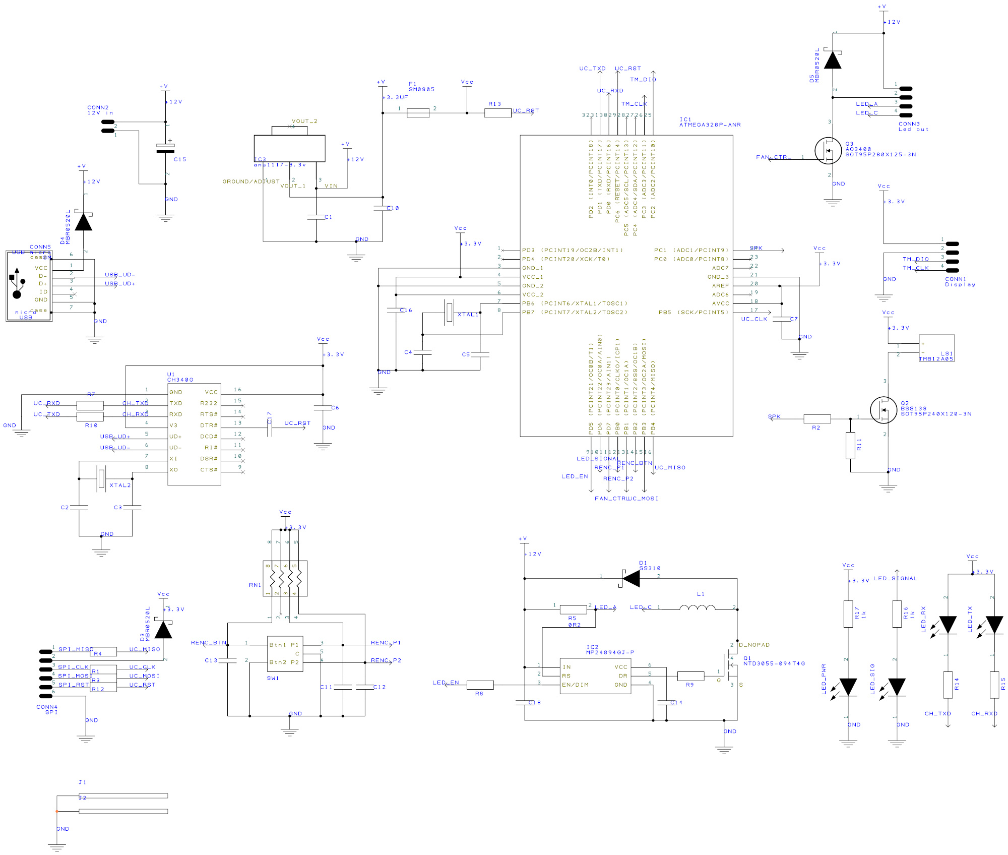
The actual led is not on the schematic; the CONN3 pins 3 & 4 connect to it offboard. Pins 1 & 2 are for a fan mounted onto a heatsink which is probably a good idea for longer exposures of several minutes.
The schematic is pretty straightforward; I built it around an Atmel 328P, which I like for this kind of small/simple project. It has ample pins and processing power for a simple task like this. A CH340G USB<>UART chip enables convenient programming over USB as well as Serial debugging. The SPI interface (CONN4) is mostly for initial programming of the factory fresh processor which won't talk to the serial port right out of the box before the necessary fuses are set.
Both the CH340G and the 328P run at 12MHz, which allows me to use 3.3V for all the logic. A 328P will usually run fine as well at 16MHz and 3.3V, but it's off-spec and I had some conveniently small 12MHz SMD crystals lying around anyway. For some reason the CH340G seems to work more reliably at 3.3V than at 5V (probably because 5V is often not actually 5, but more around 4.5 after the voltage drop of D3), so that's why I preferred 3.3V for all the logic, provided by an AMS1117.
The board takes 12V in, which is also the voltage used by the MCP24894 led driver (IC2). A 10W UV led will run at something like 9V, so with 12V input this gives more than enough headroom for the led driver to do its thing. The NTD3055 is actually a NIKOS n-channel mosfet I had lying around. I don't think it's made anymore, so not recommended for new designs.
User interfacing is done with a rotary encoder (SW1) with some hardware debounce stuff around it and a 4-digit TM1637 7-segment display (connected to CONN1).
I threw in a little power indicator LED, a 'heartbeat' status LED and some RX/TX LEDs to monitor Serial communications. They're all bog standard 0805 SMD types. I used blue for power and red for the heartbeat/status ones, and both are visible on the finished product just to the bottom left of the rotary encoder. For good measure I also included a piezo buzzer (LS1).
Crammed into the small space I figured I had left (about 4x5cm), it just (barely) fit a double-sided PCB:
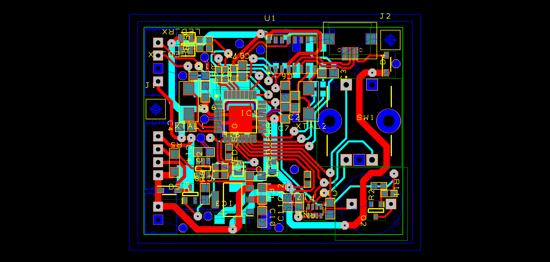
(Copper fill on both top and bottom planes removed for this image, but all black space on both sides is in reality a copper ground plane.)
I didn't take pictures of the PCB because I don't feel like disassembling it all again, but suffice to say that it works, but it's ugly. I DIY all my PCB's and while they generally work after some obligatory troubleshooting, they never end up looking like Miss Universe (which I don't mind, as long as they do their job).
Here you can see the bottom of the finished box; the little white square is the actual light surface of the UV LED.
And here's what's inside:
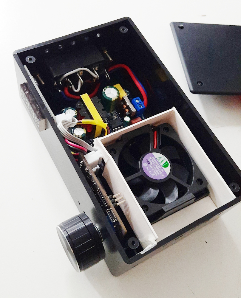
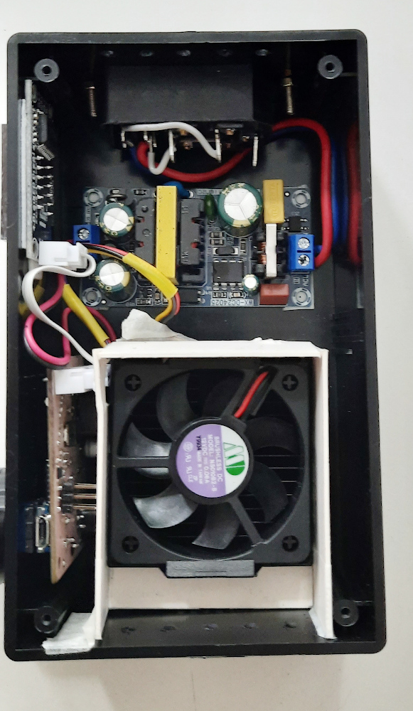
Second picture, just above shows:
* At the top a standard 230V device plug with fuse and switch.
* Just below it a 230VAC-12VDC 2A SMPS module (cheap Chinese junk, works fine, but has no primary-side filtering.)
* To the left of the 12V supply you can see the PCB of the TM1637 module. I had some of these lying around anyway which I bought for another project and it is kind of appropriate for this contraption.
* Bottom left shows the vertically mounted processor PCB with the micro-USB jack and the SPI connector visible. The PCB mounts to the case by means of the rotary encoder which is soldered directly onto the PCB.
* The UV led is hidden below the fan and the heatsink; those are probably from an old 1st generation Pentium processor and I had those sitting in the parts bin anyway, so put them to good use here. The white cardboard thingy is an airduct which allows the fan to suck air from the case through the heatsink fins, taking the heat from the LED out of the case through the ventilation holes at the bottom of the picture. Above the 230V power inlet there's another series of holes that allow cool air to be sucked in. It's all very basic and improvised, but works fine.
The control software is written in Arduino C++, using a state machine as a central coordinating mechanism for all the inputs & outputs. I did the software architecture for this for my color enlarger project that is underway (and has been for quite a while...) so I reused some software components for this device. This also makes the software kind of tp-heavy and bloated for this purpose (the enlarger head will run on an ESP32S WROOM with oodles of processing power & memory in comparison with the old and trusty 328P), but performance is good and this was the quickest way to get the job done. The device doesn't do anything complicated:
* it allows the user to set the time (in seconds) using the rotary encoder
* shows the time set on the 4-digit display and shows a countdown timer during exposure
* does some led blinks (every second during exposure) and beeps (on exposure start, end and cancel)
* turns on the UV led and the cooling fan when the button is pushed
* during exposure the countdown can be canceled by pushing the button again
* after a successful exposure (i.e. one that counts down to zero without being cancelled by the user) the exposure time that was set is stored into EEPROM so it's loaded the next time the device is switched on
That's basically it. No fancy PWM, fan delays, temperature monitoring, manipulation of system configuration etc. Could all be done, but I considered it overkill for a quick & dirty project like this.
Hope you enjoyed the writeup! Not sure if it's useful in any way to anyone and I don't intend this to be a build guide that allows anyone to copy the project (feel free if you want to). I just felt like sharing a bit of what I've been wasting time on as of late, which isn't exactly photography, but still tangentially related to it.
Excuse the abysmal cameraphone pics. Just to get an impression of the finished contraption.
The main reason for making this is to see if the quasi-point source of a COB LED would give a noticeable resolution advantage over the large bank of UV-B tubes I've been using so far. Not really of of necessity, since the UV-tube source actually works fine as it is, but just...you know, because I can.
It's not going to win any beauty contests in any department - mechanical construction, electronics design or software engineering. It's all done very quick & dirty, but it seems to work. Haven't tested it yet for its intended application, but all seems fine so far. I have in mind to mount it underneath a shelf above my workbench with a couple of brackets so it's conveniently out of the way when I don't need it, but close at hand whenever I do. So that's why the LED output is actually at the bottom of the box as you can see further down this post.
Here's the schematic:
The actual led is not on the schematic; the CONN3 pins 3 & 4 connect to it offboard. Pins 1 & 2 are for a fan mounted onto a heatsink which is probably a good idea for longer exposures of several minutes.
The schematic is pretty straightforward; I built it around an Atmel 328P, which I like for this kind of small/simple project. It has ample pins and processing power for a simple task like this. A CH340G USB<>UART chip enables convenient programming over USB as well as Serial debugging. The SPI interface (CONN4) is mostly for initial programming of the factory fresh processor which won't talk to the serial port right out of the box before the necessary fuses are set.
Both the CH340G and the 328P run at 12MHz, which allows me to use 3.3V for all the logic. A 328P will usually run fine as well at 16MHz and 3.3V, but it's off-spec and I had some conveniently small 12MHz SMD crystals lying around anyway. For some reason the CH340G seems to work more reliably at 3.3V than at 5V (probably because 5V is often not actually 5, but more around 4.5 after the voltage drop of D3), so that's why I preferred 3.3V for all the logic, provided by an AMS1117.
The board takes 12V in, which is also the voltage used by the MCP24894 led driver (IC2). A 10W UV led will run at something like 9V, so with 12V input this gives more than enough headroom for the led driver to do its thing. The NTD3055 is actually a NIKOS n-channel mosfet I had lying around. I don't think it's made anymore, so not recommended for new designs.
User interfacing is done with a rotary encoder (SW1) with some hardware debounce stuff around it and a 4-digit TM1637 7-segment display (connected to CONN1).
I threw in a little power indicator LED, a 'heartbeat' status LED and some RX/TX LEDs to monitor Serial communications. They're all bog standard 0805 SMD types. I used blue for power and red for the heartbeat/status ones, and both are visible on the finished product just to the bottom left of the rotary encoder. For good measure I also included a piezo buzzer (LS1).
Crammed into the small space I figured I had left (about 4x5cm), it just (barely) fit a double-sided PCB:
(Copper fill on both top and bottom planes removed for this image, but all black space on both sides is in reality a copper ground plane.)
I didn't take pictures of the PCB because I don't feel like disassembling it all again, but suffice to say that it works, but it's ugly. I DIY all my PCB's and while they generally work after some obligatory troubleshooting, they never end up looking like Miss Universe (which I don't mind, as long as they do their job).
Here you can see the bottom of the finished box; the little white square is the actual light surface of the UV LED.
And here's what's inside:
Second picture, just above shows:
* At the top a standard 230V device plug with fuse and switch.
* Just below it a 230VAC-12VDC 2A SMPS module (cheap Chinese junk, works fine, but has no primary-side filtering.)
* To the left of the 12V supply you can see the PCB of the TM1637 module. I had some of these lying around anyway which I bought for another project and it is kind of appropriate for this contraption.
* Bottom left shows the vertically mounted processor PCB with the micro-USB jack and the SPI connector visible. The PCB mounts to the case by means of the rotary encoder which is soldered directly onto the PCB.
* The UV led is hidden below the fan and the heatsink; those are probably from an old 1st generation Pentium processor and I had those sitting in the parts bin anyway, so put them to good use here. The white cardboard thingy is an airduct which allows the fan to suck air from the case through the heatsink fins, taking the heat from the LED out of the case through the ventilation holes at the bottom of the picture. Above the 230V power inlet there's another series of holes that allow cool air to be sucked in. It's all very basic and improvised, but works fine.
The control software is written in Arduino C++, using a state machine as a central coordinating mechanism for all the inputs & outputs. I did the software architecture for this for my color enlarger project that is underway (and has been for quite a while...) so I reused some software components for this device. This also makes the software kind of tp-heavy and bloated for this purpose (the enlarger head will run on an ESP32S WROOM with oodles of processing power & memory in comparison with the old and trusty 328P), but performance is good and this was the quickest way to get the job done. The device doesn't do anything complicated:
* it allows the user to set the time (in seconds) using the rotary encoder
* shows the time set on the 4-digit display and shows a countdown timer during exposure
* does some led blinks (every second during exposure) and beeps (on exposure start, end and cancel)
* turns on the UV led and the cooling fan when the button is pushed
* during exposure the countdown can be canceled by pushing the button again
* after a successful exposure (i.e. one that counts down to zero without being cancelled by the user) the exposure time that was set is stored into EEPROM so it's loaded the next time the device is switched on
That's basically it. No fancy PWM, fan delays, temperature monitoring, manipulation of system configuration etc. Could all be done, but I considered it overkill for a quick & dirty project like this.
Hope you enjoyed the writeup! Not sure if it's useful in any way to anyone and I don't intend this to be a build guide that allows anyone to copy the project (feel free if you want to). I just felt like sharing a bit of what I've been wasting time on as of late, which isn't exactly photography, but still tangentially related to it.


 Yeah, light intensity isn't half bad. Better than I anticipated.