Is there interest in a New Rapid Rectilinear lens?

Carved bench

A
Carved bench

  • 0
  • 3
  • 66
Anthotype-5th:6:25.jpg

A
Anthotype-5th:6:25.jpg

  • 6
  • 4
  • 131
Spain

A
Spain

  • 2
  • 0
  • 99
Nothing

A
Nothing

  • 2
  • 3
  • 180

Recent Classifieds

Forum statistics

Threads
198,057
Messages
2,768,998
Members
99,547
Latest member
edithofpolperro
Recent bookmarks
0

Dr Croubie

Member
Joined
Mar 21, 2013
Messages
1,986
Location
rAdelaide
Format
Multi Format
There are tons of heavier lenses available in 8 x 10 for almost all focal lengths.
What there aren't a lot of is light weight lenses that cover 8x10 with the generous movement in this focal lengths.

I did recently pick up a particularly interesting lens called a Graphic-Kowa 210 f/9, what's interesting about it is that I'm told that this is an "earlier design" which had a coverage for 11x14 with a tiny bit of wiggle room, whereas the later generations of this same lens were all only 8x10 coverage.
If this is true, the design already exists for a 210mm that covers 11x14 with movements, that could possibly be improved with modern technology.
Now I have purchased the lens and have it in my kit, and have shot a few 8x10 images with it, but I do not have access yet to an 11x14 camera to truly test the theory of the seller that it should cover 11x14 because of some kind of lens element reflection number.

Well, from the design so far being at 'about 200g of glass', I'd call that lightweight. Put that in a mount and shutter and it's still probably less than 500g / 1lb.
I think I said earlier that a 155mm Grandagon or a 165mm Super Angulon are both well over 1kg, nearly 3lb. So a weight savings of 50% or better is great.
And this new one is f/6.8 in a #1, the SA is f/8 and both are in a #3.
I don't think you'll get much smaller or lighter than that.

As for the 210mm Kowa, the 'counting of reflections' is how to tell what version it is.
There were two 'Computar' 210mm lenses, both are on the list here.
One is the 'computar symmetrigon' f/6.3, 4/4 style, specced to cover 308mm (I've got one of these and it almost reaches 8x10 at min aperture but not completely, I'll use it for 4x10s fine though).
The other is the 'computar f9' f/9, 6/4, specced to cover 325mm (although allegedly goes further stopped down), this was also sold as 'graphic kowa' and is the version you've got.

I'm not sure which of the 'symmetrigon' and 'f9' versions is the earlier, but it's strange that Fujinon lenses also had larger coverage in their Single Coated 'W' series (80 degrees, 210mm = 352mm IC) compared to their EBC 'NW' series (71 degrees, 210mm = 300mm IC). They also changed from 6/4 to 6/6 for most in the new series (210 NW was 6/5 allegedly), so the newer ones were probably sharper and better corrected, but they reduced the coverage. Or the 'coverage' may actually be fairly similar but their definition of 'acceptable' narrowed for the newer series? I'd have no idea without testing both side-by-side.
 

StoneNYC

Member
Joined
Aug 5, 2012
Messages
8,345
Location
Antarctica
Format
8x10 Format
Well, from the design so far being at 'about 200g of glass', I'd call that lightweight. Put that in a mount and shutter and it's still probably less than 500g / 1lb.
I think I said earlier that a 155mm Grandagon or a 165mm Super Angulon are both well over 1kg, nearly 3lb. So a weight savings of 50% or better is great.
And this new one is f/6.8 in a #1, the SA is f/8 and both are in a #3.
I don't think you'll get much smaller or lighter than that.

As for the 210mm Kowa, the 'counting of reflections' is how to tell what version it is.
There were two 'Computar' 210mm lenses, both are on the list here.
One is the 'computar symmetrigon' f/6.3, 4/4 style, specced to cover 308mm (I've got one of these and it almost reaches 8x10 at min aperture but not completely, I'll use it for 4x10s fine though).
The other is the 'computar f9' f/9, 6/4, specced to cover 325mm (although allegedly goes further stopped down), this was also sold as 'graphic kowa' and is the version you've got.

I'm not sure which of the 'symmetrigon' and 'f9' versions is the earlier, but it's strange that Fujinon lenses also had larger coverage in their Single Coated 'W' series (80 degrees, 210mm = 352mm IC) compared to their EBC 'NW' series (71 degrees, 210mm = 300mm IC). They also changed from 6/4 to 6/6 for most in the new series (210 NW was 6/5 allegedly), so the newer ones were probably sharper and better corrected, but they reduced the coverage. Or the 'coverage' may actually be fairly similar but their definition of 'acceptable' narrowed for the newer series? I'd have no idea without testing both side-by-side.

Thanks, the seller said there were specifically TWO graphic-Kowa versions.

All I can tell you for sure is that on my Chamonix 8x10, I can give it all the rise/fall and shift in all four directions and I can't hit the edge of the lens whatsoever. When wide open.
 

StoneNYC

Member
Joined
Aug 5, 2012
Messages
8,345
Location
Antarctica
Format
8x10 Format
:laugh::laugh: I think your autocomplete/correct needs to be quarantined.

Anyway, small/sharp/wide coverage adds up to... very slow lenses. The reading glasses/no dark cloth crowd don't like this. Slow wides can be a pain, unless you use Fresnel screen the corners get hard to see even with an angled loupe.

I don't care about aperture the 450 C is F12.5....

I can see perfectly fine on my GG, again it's landscape work, light for hiking, I don't need F/5.6 or anything.
 
OP
OP
Nodda Duma

Nodda Duma

Member
Joined
Jan 22, 2013
Messages
2,685
Location
Batesville, Arkansas
Format
Multi Format
Front group alone has a 362 mm focal length.

Rear group alone has a 256 mm focal length.


Stopped down they look really good on axis but of course coma becomes a problem at the edges and distortion is no longer corrected (the design lost its symmetry).
 
OP
OP
Nodda Duma

Nodda Duma

Member
Joined
Jan 22, 2013
Messages
2,685
Location
Batesville, Arkansas
Format
Multi Format
attachment.php


attachment.php


The two outer elements are the same on each side of the stop, and made out of inexpensive glass. Only the doublets are asymmetrical. After letting the optimization run over the weekend, the performance is about as good as an entirely non-symmetrical lens would be. This will help cut cost further.

I made a couple more tweaks to the optimization inputs, and I'll let it run unattended for several days. While that's going I'll put together some information on the performance to give you a better idea of what it can do. When I'm satisfied that it's been tweaked as best it can, I'll generate drawings to get the optics quoted.

I also need to cross-post to the large format photography forum. I wanted to wait until I could get closer to getting quotes.

I tried to cut out the doublets and replace with singlets but wasn't as satisfied with the results.

-Jason
 

Attachments

  • lens 17 nov.png
    lens 17 nov.png
    61.1 KB · Views: 322
  • lens 17 nov 2.png
    lens 17 nov 2.png
    43.8 KB · Views: 313
OP
OP
Nodda Duma

Nodda Duma

Member
Joined
Jan 22, 2013
Messages
2,685
Location
Batesville, Arkansas
Format
Multi Format
Michael just send me PM or start a thread and point me at it :smile:
 
Last edited by a moderator:
OP
OP
Nodda Duma

Nodda Duma

Member
Joined
Jan 22, 2013
Messages
2,685
Location
Batesville, Arkansas
Format
Multi Format
BOKEH

15204409713_2c42458ae5_b.jpg


I generated this by taking a photo of stars and running it through Zemax (my lens design software). It can simulate how the lens will perform, and in my experience it is a very accurate tool. I once did this for an eyepiece which I had designed and assembled only to find out there was a slight coloring / diopter shift at the corners...just enough to cause text on the microdisplay to look like a double-image (astigmatism). The image simulation showed this design flaw perfectly once I corrected how I had been modeling the eye pupil (and yes I have a very accurate model of the Mk. I Eyeball). Anyways, for this BOKEH image, I set the focus of the lens at 2m and then "imaged" these stars at infinity. Kind of like if you focused on a person standing 2m away and there's bright stuff way in the back, like light coming through tree leaves or whatever. So you get to see what the bokeh will look like.

I do this at very high resolution (8000 x 6400, each pixel representing 31.25 micrometers). I only posted a 1280 x 1024 image here.... if you want to see the really high image version you can get to that here: https://www.flickr.com/photos/noddaduma/15204409713/sizes/l/


Next post I'll put some in-focus images up.
 
Last edited by a moderator:
OP
OP
Nodda Duma

Nodda Duma

Member
Joined
Jan 22, 2013
Messages
2,685
Location
Batesville, Arkansas
Format
Multi Format
Linked here is the original image that I use as my "source". The original is 6400 x 8000... each pixel represents an area 31.25 x 31.25 um at the film plane

https://www.flickr.com/photos/noddaduma/15638653078/sizes/l

Of course this was taken with a real camera, so it's not "perfect"... but at least you can see the before and after.

Original (reduced resolution). I think the original was Fuji Neopan 100 taken with a Pentax 67 and the Pentax 75mm f/4.5.

15638653078_e554fbbaaf_z.jpg


The output is then generated at selected stops as shown (and the different resolutions including the original 8000 x 6400 linked) below. Again, this simulates how the actual lens will image a scene... the paths the light rays follow are calculated in the lens design software using the fundamental physics model that the design is based on. It takes about 10-15 minutes to generate each frame, but it gives a very good indication of what the actual lens will do:

At f/6.3: https://www.flickr.com/photos/noddaduma/15639281720/sizes/l

Can you get to that?

15639281720_b1bc89432e_z.jpg


Of course you see the roll-off in illumination due to cos^4 law (light hitting the film plane at high angles) as well as the slight vignetting necessary to fit the optics onto the Copal 1 shutter. You lose about 1 3/4 stop of light at the corners and as you can see it's a gradual rolloff. In the real lens the coating performance may impact this but I don't think significantly so. I'll just have to be careful specifying the coatings. I think you guys use an apodization filter to take care of this problem, right? I looked into trying to model one in the system but figured eh, you could use your imagination. It's kind of a pain to set up.

Inspecting the high-resolution image for resolution performance I see some slight softening at center and a bit more noticeable aberrations at the corners from pushing the design to its limit. Color is well-controlled (While it's a B&W "scene", it's treated as a color image when run through the image simulation. I looked for color fringes around bright spots or contrast edges but didn't see any).

One thing you may notice is a "warping" of the output image. This is an artifact of the image simulation, and is not due to distortion or the lens itself.

At f/11: https://www.flickr.com/photos/noddaduma/15800524776/sizes/l

Notice that the illumination rolloff is a bit better than at f/6.3. This is because you are no longer vignetting like when the lens is wide open (f/8 does not vignette either, btw). At f/8 and greater, you lose about 1 1/2 stops.

Looking at the high-resolution image the central region has sharpened up as you'd expect, and the corner aberrations are now under control.

15800524776_e666436aea_z.jpg


Here is f/16: https://www.flickr.com/photos/noddaduma/15800579456/sizes/l

The relative illumination falloff doesn't change from the prior photo since there is no longer any change due to vignetting. So you're still losing about 1 1/2 stops.

15800579456_8dfda4167c_z.jpg


Ok here's f/22. By now you're pretty much diffraction-limited throughout the scene except maybe at the very corners. f/16 and f/22 seem to be the lens' sweet spot for resolution.

https://www.flickr.com/photos/noddaduma/15822473651/sizes/l


hmm... looks like the simulation choked and separated the color channels in part of the image (top left corner and top right). Probably due a bug in the software rev I run at home. Just keep in mind that's an artifact of the simulation itself and not due to the optical performance of the lens.

15822473651_85a8daefc6_z.jpg


So I'm pretty happy with the lens as it is. Probably about time to generate the lens drawings and send them out to the shops to get quotes.
 
Last edited by a moderator:

winterclock

Member
Joined
Oct 9, 2010
Messages
101
Location
Cape Cod, MA
Format
Large Format
What happens if you move the front element out like the Wollensak soft focus adjustment? This could be an inexpensive bonus feature if it does the same thing.
 
Joined
Sep 11, 2012
Messages
158
Location
San Francisc
Format
Large Format
I don't know if it's been mentioned before but I would try and stick with a common filter ring size for 8x10 and 4x5 LF lenses, those being 52, 67, and 77, that would make it easier for us to use existing filter sets and set-up rings.


Sent from my iPad using Tapatalk
 
Joined
Sep 11, 2012
Messages
158
Location
San Francisc
Format
Large Format
One other design you might want to look at for wide angle in 8x10 is the combination of the front element of the 210mm Computar f9 with the back element of the 150mm Computar f9 which apparently creates a 165mm f9 which is very small in a Copal 1. These lenses have 95 degree of coverage. I have made one of these creations and will be testing it on my 14x17 to gauge coverage.


Sent from my iPad using Tapatalk
 
Joined
Sep 11, 2012
Messages
158
Location
San Francisc
Format
Large Format
Otherwise, I'd like to say this effort is wonderful to follow and I'll be happy to support it with one order. Hopefully we can have a series of shutter mountable lenses in hard to find FL which are light weight, cheaper, and have good performance. APO and MC are key in 4x5 and to some extent 8x10 but above that size most people are only shooting B&W and contact printing so some corners might be able to be cut in the interest of cost.


Sent from my iPad using Tapatalk
 
OP
OP
Nodda Duma

Nodda Duma

Member
Joined
Jan 22, 2013
Messages
2,685
Location
Batesville, Arkansas
Format
Multi Format
Question: if I want to look at shift lens characteristics, for 8x10 I should examine an 11x14 area?
 

LJH

Member
Joined
Nov 25, 2008
Messages
724
Location
Australia
Format
ULarge Format
Question: if I want to look at shift lens characteristics, for 8x10 I should examine an 11x14 area?

To me, this is a bit like the tail wagging the dog. It's all well and good to have a lens with a large IC; however, I would suggest that you need to understand WHY a large IC is required. Primarily, I believe that you get the answer to this by asking what sort of shooting is envisaged (landscape, architecture etc), on what format, and then what focal length.

Once you know intention and FL, then the IC comes in to play.

As I have been requesting, I'd like to see a 200-210mm lens with an IC large enough for my 7x17 (i.e. ultra wide). I wouldn't use front movements with this lens, as it would require more IC than I feel that the lens would offer (without becoming a behemoth like the 200mm Grandegon/210mm SA). However, for someone shooting 8x10, this lens would be a moderate wide with almost more movement potential than any 8x10 camera can provide. Perfect for 8x10 architectural and landscape shooters.

So, under my suggestion in the top paragraph, this goes Architecture - 8x10 - 200mm - large image circle. Or, for me, it would go Landscape - 7x17 - 200mm - covering IC.

Hope that this makes sense...
 

Dr Croubie

Member
Joined
Mar 21, 2013
Messages
1,986
Location
rAdelaide
Format
Multi Format
Besides the usage (which is probably most important), I'd be looking at percentages rather than mm.
A wide lens like this is going to be for landscape and/or architecture. Landscapes use a bit of shift/tilt, architecture a lot of shift (well, depending on the scene of course).

Take, for example, my Fujinon 90mm SWD. It has excess coverage for 53mm & 48mm. As a percentage of 4x5 that's 44 / 50%, ie, a lot. I've never run out of shift nor tilt with this lens on 4x5.
My 180mm Symmar-S has another 1cm or so image circle bigger than the SWD. I can't imagine shifting a widish normal that much ever.

For a landscape, I'd say 30% shift is sufficient for most uses, which is 73/60mm on 8x10 (to steal numbers, that's what a 300mm Nikkor W would do, IC of 420mm).
And coincidentally, that lens has 5mm of shift on 11x14", so that's not far off the mark.
Also, 80mm rise is just about what my Cambo SCX Monorail can handle when racked out, less closer in because I don't have bag bellows (yet).

For architecture, that's probably not going to be enough for some though, and that's when you have to start angling the base and tilting standards to get more rise.
But for most normal uses, you can probably even get away with less, like a 400mm IC.
This is where tastes start coming into it. Some people would trade less IC for sharper to that point, some would rather have more IC even if it gets a bit softer on the way there, so you'll never get a straight answer unfortunately...
 
OP
OP
Nodda Duma

Nodda Duma

Member
Joined
Jan 22, 2013
Messages
2,685
Location
Batesville, Arkansas
Format
Multi Format
Ok I looked at the field angles beyond what I designed for.

Maximum field of view that will pass through the glass is 104.6 degrees. At +/- 52.3 degrees the illumination at the film plane falls to zero. So let's see..

Basic geometry says focal length * tan(half FOV) = image circle radius. So the largest possible image circle Diameter is 2*(165 mm * tan(52.3) ) = 427 mm, or 16.8" diameter image circle (a 13.12" x 10.5" film plane at the same aspect ratio of 8 x 10).

I could open that up but it directly affects weight and cost.

I'm not going to say anything about the image quality out there....nor the illumination. Actually it doesn't look bad (see attached). You probably wouldn't see the aberrations because it'd be too dim! When we design the barrel I'll make sure that nothing (other than the Copal 1 shutter) blocks that circle.

https://www.flickr.com/photos/noddaduma/15645497149/sizes/l


15645497149_74083c71b7_z.jpg
 
OP
OP
Nodda Duma

Nodda Duma

Member
Joined
Jan 22, 2013
Messages
2,685
Location
Batesville, Arkansas
Format
Multi Format
I have one more trick to try... the cemented doublets *might* be able to be eliminated without sacrificing too much performance. Doublets cost more than singlets (of course) because that's 4 surfaces to polish instead of 2 and then touch labor bonding them together. I'm going to let that design optimize overnight and see what happens.

Tomorrow night I meet with another optical engineer to let him review the design, as well as the ME who will design the barrel. Then I drink lots of beer and generate drawings.


Right now it's time for a little bit of War Thunder.
 

StoneNYC

Member
Joined
Aug 5, 2012
Messages
8,345
Location
Antarctica
Format
8x10 Format
I have one more trick to try... the cemented doublets *might* be able to be eliminated without sacrificing too much performance. Doublets cost more than singlets (of course) because that's 4 surfaces to polish instead of 2 and then touch labor bonding them together. I'm going to let that design optimize overnight and see what happens.

Tomorrow night I meet with another optical engineer to let him review the design, as well as the ME who will design the barrel. Then I drink lots of beer and generate drawings.


Right now it's time for a little bit of War Thunder.

Does "war thunder" = snoring?

You're impressive, thanks for joining this crazy place :smile:
 
OP
OP
Nodda Duma

Nodda Duma

Member
Joined
Jan 22, 2013
Messages
2,685
Location
Batesville, Arkansas
Format
Multi Format
hah! I only get one snore in before my wife kicks me.

War Thunder = http://warthunder.com/us


Actually my days typically run 5am to 10pm-12pm. I started off life as an early bird, then college made me a night owl. Now I'm both. Too much stuff to do and too little time. I'll sleep when I'm dead!


Actually I forgot that I need to match radii to test plates. Every optical shop has a very large set of test plates with values made available to the optical design software. Test plates are glass discs with radii carefully measured and calibrated... as the optician polishes out an optic, he can quickly clean the surface and place the test plate on the part to view the Newton Rings (you are googling these terms, right?). It quickly tells the optician how far out he is from a matching radii. Otherwise he has to use other methods which take longer (requires removing the parts from the polishing spindle and measuring on an interferometer or similar).

On my end during design, I match the radius of curvature of each surface to existing test plates and the cost goes down a little bit because the labor is reduced. Usually helps in the 500-1500 production run range. Less than that it doesn't gain you much (but it does gain you something). More than that the cost of fabricating a new test plate is insignificant when amortized over the production run.

-Jason
 
Last edited by a moderator:
OP
OP
Nodda Duma

Nodda Duma

Member
Joined
Jan 22, 2013
Messages
2,685
Location
Batesville, Arkansas
Format
Multi Format
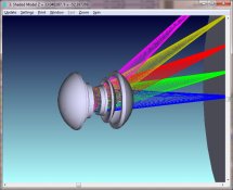
Shaded model. What a beaut!

attachment.php


Actually the 3D rendering in Zemax is crap. You'll have to wait until the solid model is generated to see how gorgeous it is. I can picture it now in my head and it is beautiful.

The largest elements are 60mm diameter (just over 2 1/8" diameter). Total glass weight is 192 grams, or 0.42 pounds (just over 6 3/4 oz). My Mech Eng says the metal should only be about 100 grams but we'll see. I think 200 grams is more realistic which would put the assembled barrel weight at just under a pound...add the Copal 1's ~120 gram weight and you get what, like 1 1/4 lb total weight to put on your lens board. Of course if he's right then I've hit 1 lb almost exactly.

So this is what you'd call a 6/8 grouping (is that right?)

The 6 / 6 grouping is actually coming in. There's one glass type which I need to look at cost of a bit closer but I like what I see going on with that all-singlet design. It's performance will be very similar to this baby.
 

Attachments

  • shaded.jpg
    shaded.jpg
    110.9 KB · Views: 255

Dan Fromm

Member
Joined
Mar 23, 2005
Messages
6,805
Format
Multi Format
If I counted correctly (the front two groups look like cemented doublets but I could be mistaken) it is six elements in four groups.
 
OP
OP
Nodda Duma

Nodda Duma

Member
Joined
Jan 22, 2013
Messages
2,685
Location
Batesville, Arkansas
Format
Multi Format
Honestly I'm not sure how you divvy up the groups. To me the lenses in a design have always been interrelated and inseperable...although reading in the forum has proven that assumption incorrect. In the design world, a cemented doublet is usually considered a single lens (difference in nomenclature).

Anyways, there's two cemented doublets in the design and 4 singlets. So that'd be 8 elements divided into 6 groups?


The outer elements are singlets as well, and are traditional crown glass. Reference the line drawing in post 105.


Just a quick note to provide perspective: for symmetrical designs you'll find I talk about "the next lenses out"...by that I'm talking in reference to the aperture stop location....in a symmetrical design the lenses in an optical layout are sort of "mirrored" by the stop location.

So if I say something like "the next lenses in " or "next lenses out" I'm talking in reference to the aperture stop location.


Also, I checked the all-singlet design this morning and it came in nicely except the corners of the image plane are a little more aberrated at f/6.3. I think this is great because cemented doublets are roughly 2.25x the cost of a singlet. I think the trade-off will be worth it.
 
Last edited by a moderator:
OP
OP
Nodda Duma

Nodda Duma

Member
Joined
Jan 22, 2013
Messages
2,685
Location
Batesville, Arkansas
Format
Multi Format
Hi Michael,

Let me answer your 2nd question first: The answer has to do simply with economy of scale. Spherical elements are inexpensive because you can block up several lenses on a polishing spindle and polish them all out at the same time. The radii are determined by the radii of the polisher. The labor for the optician is therefore spread out across several lenses. So roughly (excluding cost of material), an order for 100 lenses will cost about the same as an order for 10 lenses, but the *per unit cost* will be 1/10th for the larger order.

Molded aspheres are similar.... you can fabricate a single mold block which generates 10, 100, whatever aspheric elements at the same time. The labor for the one optician running the mold machine is then distributed (amortized) across all those elements. Or, you have a single mold block which stamps out 100s of aspheres as part of an automatic process. While the per unit cost for these can get down to similar values as for spherical lenses, note that the lenses are fabricated individually (one per mold), as opposed to many spherical lenses being polished out at once. That is a subtle but important distinction.

Now say you weren't smart and used non-moldable glass for your asphere or you had a very small order where the cost of a mold was not feasible. The asphere can then only be generated individually. You cannot block up many lenses at once and expect to get an aspheric surface...the grinding and polishing stroke always generates spherical surfaces. You can generate the base spherical curve, but then you have to do something else to get your final aspheric surface. To get an asphere you have to change the polishing stroke in such a way that you cannot polish out several elements at once. Look up Texereau's "How to Make a Telescope" I think there's a pdf copy online and he describes why this is so in his book (great reference for making a telescope primary mirror at home, btw).

So, the optician's labor which was amortized across all the lenses being polished at once is now concentrated into each aspheric element.... Because he has to touch every element individually, you have to pay for that touch labor.

That said, there are aspheric polishing machines which reduce the cost of the touch labor, but they still have to treat each lens individually and the overhead cost is rolled into each one of those lenses.


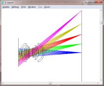
I think perhaps your first question could be answered in a separate thread to discuss navigating around a ray trace diagram. But maybe this will do for now: Real quick, however, examine the ray trace in post 104. You'll see a diagram of the lens layout -- a cutaway if you will of the glass elements -- with ray traces. To the left is the object side of the system... the rays are all coming from infinity focus and therefore parallel. Different colors = different field angles (angle from the optical axis). The blue lines are rays coming from 0 degree field angle, or from straight ahead. I only show about 50mm of ray length on the object side so that you can see the lens diagram at a proper scale, but they are all parallel and originate from "infinity" in the model. Look in particular at the rays denoted by the blue lines. That is a "cone" of rays coming from infinity. The center line of the blue group is the optical axis. The edges of the blue "cone" pass through the edge of the aperture stop located in the middle of the lens group. In fact, the edges of each different-colored cone all meet each other at the edge of the aperture stop. That's where all the rays seem to come together before going on through the rest of the lenses. These "cone edge rays", by the way, are called the marginal rays. The marginal ray path is straightforward to calculate and, along with the chief ray, were used before the age of computers to design lenses by hand. In any case, the aperture stop, therefore, defines how much light enters the system.

There is one exception: In the diagram note the extreme angle cone represented by the pink lines are vignetted purposefully for improved performance when the stop is wide open. So the edge of its cone doesn't meet the others. However one of those pink lines near the center of that cone or bundle does cross at the center of the stop. If that field angle was not vignetted it would be the center ray in that cone. That is the chief ray that I mention above. The optical system can be described completely by tracing (ie calculating the path of) the marginal ray and chief ray.

If you were ever only going to look straight ahead, then the lenses would only need to be as wide as the width of the blue "cone". As you know, that's not the case.... the lenses must be wide enough to accommodate all the field angles being imaged (80 degrees as shown), plus some extra for physical mounting. The diameter required to accommodate the light cone from all the imaged field angles passing through a lens (element) is called the clear aperture (CA). The actual physical diameter of the lens is called the physical diameter, and is usually about 4% greater than the C.A. Now imagine one of those lenses in a barrel and held in place by a retaining ring. If the resultant clear aperture of the lens is smaller than the clear aperture required by your stop size, then you get vignetting.

To help with optical terms, google MIL-STD-1241 "Optical Terms and Definitions" which may help define the terms a little better.

You can also look up MIL-HDBK-141 "Optical Design". Both of these documents are well-known classic references in my field, and they are also free.


-Jason
 
Last edited by a moderator:
Photrio.com contains affiliate links to products. We may receive a commission for purchases made through these links.
To read our full affiliate disclosure statement please click Here.

PHOTRIO PARTNERS EQUALLY FUNDING OUR COMMUNITY:


Ilford ADOX Freestyle Photographic Stearman Press Weldon Color Lab Blue Moon Camera & Machine
Top Bottom