I recently bought one of these cameras on eBay and sure enough, it had the dreaded LCD problem. Only a few of the LCD segments worked on the top panel, and worse, the shutter speeds in the viewfinder were dead too. I looked the problem up and apparently it is a common problem for segmented LCD panels on watches, calculators, etc.
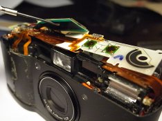
LCD panels are connected to the main circuit boards in these devices with a plastic ribbon cable which has conductive rubber strips embedded in it. The ribbon cable is glued down to the circuit board using a special film which is conductive through its thickness but not conductive in the other directions. Unfortunately this stuff tends to degrade over time which gives the classic GR1 problem.
However, if you're handy you can remove this film and either tape the cable in place and install something to push it down onto the circuit board contacts, or you can buy new adhesive film (3M Anisotropic Conductive Film 9703, available on eBay for repairing iPods and such) and replace it. I'll briefly explain below.
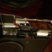
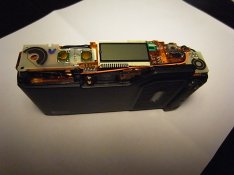
First you need access to the ribbon cable. Remove the rubber grip wrapped on the front and right side of the camera, which is just stuck down with a glue of sorts. This gives you access to two screws which hold the top cover on. Remove these. Also remove the viewfinder/power switch bezel, held on with one screw which is easily visible. Finally, there is one hidden screw which is inside the film compartment at the extreme left of the camera, beside the takeup spool. Once you remove this, you can take the top cover off. There is nothing you need to worry about here except you can easily lose the rubber part of the rewind button at the top left corner of the camera.
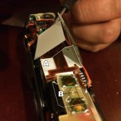
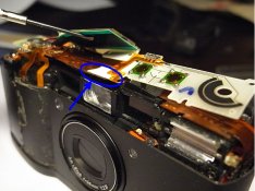
Once you have the top off, the rest is relatively easy. Take off the black plastic holder for the LCD. The hard circuit board on the left side which has the button contacts for the exposure compensation, timer, and mode buttons needs to come off; it's held down by a single screw. Now you can move the LCD out of the way, and bend out of the way (gently!) the flexible circuit board which obstructs the LCD ribbon attachment. Using a warm soldering iron or similar, you can warm up the attachment and gently remove it from the circuit board underneath. There are a series of gold pins which the ribbon is stuck to - you can clean these with acetone after removing the ribbon, and you can get the adhesive off the ribbon with acetone as well. Be VERY GENTLE removing the adhesive as the rubber conductive strips are also somewhat sensitive to acetone and will dissolve if you're not careful.
Once that's done, tape the edges of the ribbon cable in place so the contacts line up again. I used some thin foam tape to ensure constant downwards pressure to make sure the pins made contact. If you bought the 3M adhesive, cut a little strip and you'll need to heat it to around 100C while holding the ribbon in place to get it to set. This is a more reliable way of getting the contact to stay permanently - mine is missing 1.5 segments after I did the mod.
Reassemble and you're good to go!
Sorry for the lack of pics - I don't own a digital camera
LCD panels are connected to the main circuit boards in these devices with a plastic ribbon cable which has conductive rubber strips embedded in it. The ribbon cable is glued down to the circuit board using a special film which is conductive through its thickness but not conductive in the other directions. Unfortunately this stuff tends to degrade over time which gives the classic GR1 problem.
However, if you're handy you can remove this film and either tape the cable in place and install something to push it down onto the circuit board contacts, or you can buy new adhesive film (3M Anisotropic Conductive Film 9703, available on eBay for repairing iPods and such) and replace it. I'll briefly explain below.
First you need access to the ribbon cable. Remove the rubber grip wrapped on the front and right side of the camera, which is just stuck down with a glue of sorts. This gives you access to two screws which hold the top cover on. Remove these. Also remove the viewfinder/power switch bezel, held on with one screw which is easily visible. Finally, there is one hidden screw which is inside the film compartment at the extreme left of the camera, beside the takeup spool. Once you remove this, you can take the top cover off. There is nothing you need to worry about here except you can easily lose the rubber part of the rewind button at the top left corner of the camera.
Once you have the top off, the rest is relatively easy. Take off the black plastic holder for the LCD. The hard circuit board on the left side which has the button contacts for the exposure compensation, timer, and mode buttons needs to come off; it's held down by a single screw. Now you can move the LCD out of the way, and bend out of the way (gently!) the flexible circuit board which obstructs the LCD ribbon attachment. Using a warm soldering iron or similar, you can warm up the attachment and gently remove it from the circuit board underneath. There are a series of gold pins which the ribbon is stuck to - you can clean these with acetone after removing the ribbon, and you can get the adhesive off the ribbon with acetone as well. Be VERY GENTLE removing the adhesive as the rubber conductive strips are also somewhat sensitive to acetone and will dissolve if you're not careful.
Once that's done, tape the edges of the ribbon cable in place so the contacts line up again. I used some thin foam tape to ensure constant downwards pressure to make sure the pins made contact. If you bought the 3M adhesive, cut a little strip and you'll need to heat it to around 100C while holding the ribbon in place to get it to set. This is a more reliable way of getting the contact to stay permanently - mine is missing 1.5 segments after I did the mod.
Reassemble and you're good to go!
Sorry for the lack of pics - I don't own a digital camera


 )
)