- Joined
- Feb 9, 2010
- Messages
- 9,578
- Format
- 4x5 Format
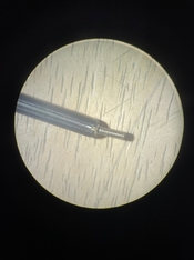
Ok, thanks. I saw some wires and potentiometers and wondered if you were changing resistors or something.
Maybe I'm missing something, you are measuring the meters selenium cell's output directly in mA and V? Why not just observe the readings of the scale?
Gathering milliamps/volts that the needle requires separately from the milliamps/volts the cell outputs with the hope of “binning” (calibrating by matching components that match each other).
So far I suspect the coils in the meters have very consistent requirements, and it’s the cells that are falling weaker. The plain cells tend to be weak below usability but many of the Weston marked cells (you can see a W logo through the bubbles) have seemed correct but measured 1/3 stop low.
Now I think I found that the apparent third stop loss was simply a problem with my test geometry (distance from source to sensor) and color temperature (infrared influence).
Also a crazy vision. This is where I need engineer friends like you. Assuming the needle-coil assembly in the meter is an ammeter, I’m thinking a buck converter could reduce the voltage and increase the amperage.
Maybe we can come up with a switching power supply circuit (transistors, inductors and capacitors) that will raise the needle readings of cells that have weakened. Or maybe allow a 4700 K calibration for cells that are already up to spec. Maybe allow a green filter too.
Last edited: