Densitometery and Contrast Index (CI)

Recent Classifieds

Forum statistics

Threads
199,029
Messages
2,784,918
Members
99,780
Latest member
Theb
Recent bookmarks
0
Status
Not open for further replies.

smieglitz

Member
Joined
Oct 18, 2002
Messages
1,950
Location
Climax, Michigan
Format
Large Format
Ornello Pederzoli II said:
...The reference points on the Kodak system are closer together. The high density point is lower in the Kodak system.

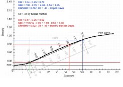
I think you have that backwards. According to Davis' methods, the Kodak numbers are higher for both DR and SBR (seederivation on the characteristic curve below). The calculations do appear to yield similar numbers for G-bar and CI though.
 

Attachments

  • CIvsGbar.jpg
    CIvsGbar.jpg
    77.8 KB · Views: 153

mikepry

Subscriber
Joined
Mar 16, 2003
Messages
454
Location
Green Cove, VA
Format
Large Format
"The purpose of the post is two fold - first wanted to understand what all those numbers/abbreviations are that I see discussed here - you know the 1.30 vs 0.12 and CI vs DR vs etc. In other words, my intent is to understand that if I used film X, exposed at Y and develop using developer A then I can expect the negative to look like P...which might be the kind of negative that I would use to print a Ziatype, on the other hand if the intended print is to be made on VC silver paper, I might want to make an adjustment to exposure or development or some other variable."

That's it....kinda. With the BTZS you START with the paper. Don Miller has written about this in the past and like him, that is what attracted me to the whole process. All the other systems leave the paper more or less out of the whole process. With BTZS you make the exposure and then and only then you decide what printing process you will use. Once decided, you develop your neg for that exposure scale (of the paper) and voila. A negative tailored for your preffered paper for that particular image. I might suggest getting the BTZS Lite along with the BTZS book as it has a nice metering section in it that goes into the incident way of working. Good luck and if you have any questions there are a few of us here familiar with the system that will be more than happy to help out.
 
Last edited by a moderator:

Ornello

Member
Joined
Apr 3, 2005
Messages
295
Format
35mm RF
smieglitz said:
I think you have that backwards. According to Davis' methods, the Kodak numbers are higher for both DR and SBR (seederivation on the characteristic curve below). The calculations do appear to yield similar numbers for G-bar and CI though.

I don't have my reference materials handy, so you could well be right. They do differ, however, and neither has anything to do with ZS. Both CI and G-bar measure the amount of development it takes to yield a certain slope based on a measured exposure intensity, such as you would have in a control strip.
 

Ornello

Member
Joined
Apr 3, 2005
Messages
295
Format
35mm RF
mikepry said:
"The purpose of the post is two fold - first wanted to understand what all those numbers/abbreviations are that I see discussed here - you know the 1.30 vs 0.12 and CI vs DR vs etc. In other words, my intent is to understand that if I used film X, exposed at Y and develop using developer A then I can expect the negative to look like P...which might be the kind of negative that I would use to print a Ziatype, on the other hand if the intended print is to be made on VC silver paper, I might want to make an adjustment to exposure or development or some other variable."

That's it....kinda. With the BTZS you START with the paper. Don Miller has written about this in the past and like him, that is what attracted me to the whole process. All the other systems leave the paper more or less out of the whole process. With BTZS you make the exposure and then and only then you decide what printing process you will use. Once decided, you develop your neg for that density range (of the paper) and voila. A negative tailored for your preffered paper for that particular image. I might suggest getting the BTZS Lite along with the BTZS book as it has a nice metering section in it that goes into the incident way of working. Good luck and if you have any questions there are a few of us here familiar with the system that will be more than happy to help out.


The density range is just that: it has nothing to do with CI or G-Bar.
 

sanking

Member
Joined
Mar 26, 2003
Messages
5,437
Location
Greenville,
Format
Large Format
smieglitz said:
I think you have that backwards. According to Davis' methods, the Kodak numbers are higher for both DR and SBR (seederivation on the characteristic curve below). The calculations do appear to yield similar numbers for G-bar and CI though.

How did you make the determination that the Kodak numbers are higher for both DR and SBR? When I compared the calculations with real plots for the two methods the DR and SBR were identical. The only practical difference between the two is that the Ilford G-Bar methos suggests a slightly higher EFS than Kodak's CI. This might, depending on the paper curve of the process, result in some differnce in the printing characteristics of the negative. But for all practical purposes the difference between G-Bar and CI is irrevelant.

BTW, my reference is the 3rd edition of Beyond the Zone System and on page 29 Davis explains how Average Gradient, or G-Bar and CI (Contrast Index) are determined. It is same as one finds in Kodak and Ilford literature.

Sandy King
 

smieglitz

Member
Joined
Oct 18, 2002
Messages
1,950
Location
Climax, Michigan
Format
Large Format
sanking said:
How did you make the determination that the Kodak numbers are higher for both DR and SBR? When I compared the calculations with real plots for the two methods the DR and SBR were identical...Sandy King


Hi Sandy,

I based that statement on the information I referenced from the first edition of Davis' BTZS book. His explanation of the G-Bar there says to use an arc of 1.5 radius from the 0.10 above fbf density value on the characteristic curve. To approximate the Kodak CI, he further states to use a radius of 2.0 units from the same 0.10 above fbf. This yields higher DR and SBR values as illustrated in the last graph I posted and, in his book, the values do appear expanded when using the 2.0 Kodak value on the figures illustrating and comparing the methods. I realize this is just an approximation of the CI the way Kodak really determines it, but the numbers work out very similarly for the three methods. They do so at a difference in values for DR and SBR though.

Please take a look at the last graph I posted in this thread and let me know if I've made an error in the calculations. (The blue numbers and lines on that graph represent my interpretaton of Davis method for approximating Kodak's CI. The red lines and figures give Ilford's G-bar according to Davis' method.) Am I missing something in my interpretation of Davis' comparison?

This is one of those perplexing things about the literature to me. I fully understand how to determine CI using Kodak's method and I use that method when doing my version of the zone system (on the rare occasion when I choose to do ZS stuff).

However, when Davis or Schaeffer or James or Barnier or Crawford or Adams or whomever states "the negative density range for such-and-such a process should be..." they all are using apparently different methods to determine/define the negative DR if you read and compare them closely, and this makes those statements irrelevant (and even detrimental) unless one adheres strictly to their method only and disregards anyone else's statements. There does not appear to be a consensus on how to determine DR - there does not appear to be a standard in that regard, at least in the popular literature I've read. Is there a formal standard definition of DR - say an ANSI or ISO standard perhaps?

OTOH, CI is straightforward as Kodak defines it. I know what it means, how it is derived, and, as a result, I know how to apply that number in my work.

Joe
 

Ornello

Member
Joined
Apr 3, 2005
Messages
295
Format
35mm RF
sanking said:
How did you make the determination that the Kodak numbers are higher for both DR and SBR? When I compared the calculations with real plots for the two methods the DR and SBR were identical. The only practical difference between the two is that the Ilford G-Bar methos suggests a slightly higher EFS than Kodak's CI. This might, depending on the paper curve of the process, result in some differnce in the printing characteristics of the negative. But for all practical purposes the difference between G-Bar and CI is irrevelant.

BTW, my reference is the 3rd edition of Beyond the Zone System and on page 29 Davis explains how Average Gradient, or G-Bar and CI (Contrast Index) are determined. It is same as one finds in Kodak and Ilford literature.

Sandy King


We are referring to the density points that are used to calculate the contrast. This has nothing to do with DR and SBR. They are the logE points used to determine the contrast.
 
OP
OP

photomc

Member
Joined
Jul 20, 2003
Messages
3,575
Location
Texas
Format
Multi Format
mikepry said:
That's it....kinda. With the BTZS you START with the paper. Don Miller has written about this in the past and like him, that is what attracted me to the whole process. All the other systems leave the paper more or less out of the whole process. With BTZS you make the exposure and then and only then you decide what printing process you will use. Once decided, you develop your neg for that exposure scale (of the paper) and voila. A negative tailored for your preffered paper for that particular image. I might suggest getting the BTZS Lite along with the BTZS book as it has a nice metering section in it that goes into the incident way of working. Good luck and if you have any questions there are a few of us here familiar with the system that will be more than happy to help out.

Thank You Mike, guess my statement was a bit oversimplified. You kind offer may be taken up...the main reason for the post was to pick the minds of those I thought could help...many of the good folks I expected to respond have and with good information, as always. Think I should at least pickup the book, already have the BTZS Lite, just not fallen into it at the level needed I think and will post additional questions as they come up. Have to admit, using the meters I have in incident mode in place of picking up a good spot meter is a pretty good motivation...would rather buy film/paper/metal than another meter...not that I have to, but have been using a 10 degree spot attachment which I think is probably OK, but not ideal.
 

photobackpacker

Advertiser
Advertiser
Joined
Mar 21, 2005
Messages
430
Location
Minnesota
Format
4x5 Format
I think this might fit under the densitometry for dummies category.

I use my densitometer very pragmatically - as a quick check on whether I am hitting my intended target. I record where I want a subject element to fall prior to exposure (zone 1 through 8) and then measure where it fell after development. This accomplishes several things - 1. It constitutes a perpetial film test regimine under field conditions (I HATE film testing). 2. It tracks my skill as a photographic technician. 3. It gives me information on negative "a" that I can use to decide what, if any, changes to make in developing negative 'b'. 4. It increases my confidence in the technical side so I can concentrate on the artistic.

I don't know how to calulate CI nor the other items discussed above but I hit my intended densities with a high degree of consistency. That's all I am looking for.
 

sanking

Member
Joined
Mar 26, 2003
Messages
5,437
Location
Greenville,
Format
Large Format
smieglitz said:
Hi Sandy,


Please take a look at the last graph I posted in this thread and let me know if I've made an error in the calculations. (The blue numbers and lines on that graph represent my interpretation of Davis method for approximating Kodak's CI. The red lines and figures give Ilford's G-bar according to Davis' method.) Am I missing something in my interpretation of Davis' comparison?

This is one of those perplexing things about the literature to me. I fully understand how to determine CI using Kodak's method and I use that method when doing my version of the zone system (on the rare occasion when I choose to do ZS stuff).

However, when Davis or Schaeffer or James or Barnier or Crawford or Adams or whomever states "the negative density range for such-and-such a process should be..." they all are using apparently different methods to determine/define the negative DR if you read and compare them closely, and this makes those statements irrelevant (and even detrimental) unless one adheres strictly to their method only and disregards anyone else's statements. There does not appear to be a consensus on how to determine DR - there does not appear to be a standard in that regard, at least in the popular literature I've read. Is there a formal standard definition of DR - say an ANSI or ISO standard perhaps?

OTOH, CI is straightforward as Kodak defines it. I know what it means, how it is derived, and, as a result, I know how to apply that number in my work.

Joe

Joe,

It has been so long since I actually graphed a curve by hand I don't even remember how to do it. I just drop the numbers in my plotting program and get the data spoon fed.

However, what I have found is that you if you follow the method described by both Kodak and Ilford for plotting contrast, CI or G-Bar, you will get the same DR but the suggested SBR for the ES of your process will be slightly different.

There is of course no single DR value that corresponds to the ES of all processes so it could be defined and determined differently than the way it is derived from the CI or G-Bar plot. In fact, for anything other than silver gelatin printing it probably should be determined differently. For another process you would just need to determine how much compaction of the shadows and compression of the highlights is appropriate for the type of work you do and the process. Obviously the DR value that you come up with will be a lot different for a long toe and long shoulder palladium print that it would be for regular silver gelatin process, and different again for a process like carbon that has a perfectly straight curve. So in that sense there is no standard DR as the range of toe and shoulder possibilities with alternative processes is very wide.

Sandy
 

smieglitz

Member
Joined
Oct 18, 2002
Messages
1,950
Location
Climax, Michigan
Format
Large Format
sanking said:
...However, what I have found is that you if you follow the method described by both Kodak and Ilford for plotting contrast, CI or G-Bar, you will get the same DR but the suggested SBR for the ES of your process will be slightly different...
Sandy


Makes sense. Since CI (or G-bar) as used by Davis equals the quotient of DR and SBR, if DR is held constant you would need to have different SBRs for variable CI. Two of the three would have to vary if the other was constant.

Thanks also for the comment about standard DRs and various processes.

Joe
 

dancqu

Member
Joined
Sep 7, 2002
Messages
3,649
Location
Willamette V
Format
Medium Format
smieglitz said:
Since CI (or G-bar)

What of Gamma. I've a Rodinal data sheet which expresses
contrast by the term gamma. Many years ago that term and
contrast were familiar to me; CI, only a few years ago and
now Ilford's G-bar. Dan
 

sanking

Member
Joined
Mar 26, 2003
Messages
5,437
Location
Greenville,
Format
Large Format
dancqu said:
What of Gamma. I've a Rodinal data sheet which expresses
contrast by the term gamma. Many years ago that term and
contrast were familiar to me; CI, only a few years ago and
now Ilford's G-bar. Dan

Gamma is the term that was widely used until in the past to describe the slope of a characteristic curve. However, it is calculated by directly dividing the DR of a negative by the SBR, which only works if you have a straight line. This is rarely, if ever the case, with modern films, so CI and G-Bar, which includes some of the toe and shoulder in the calculation, have almost universally replaced Gamma. The difference between Gamma and CI/G-Bar depends a lot on the curve itself but can be quite great in practice.

Sandy King
 

smieglitz

Member
Joined
Oct 18, 2002
Messages
1,950
Location
Climax, Michigan
Format
Large Format
I've never used gamma as a measure but as I understand it, the problem with that measurement (and why it has largely been abandoned) has to do with where you measure the slope of the characteristic curve. As Sandy has indicated, gamma works fine where the slope is a straight line, but if you take the typical film curve, the slope is constantly changing. IIRC gamma is equivalent to the slope representing the tangent of the curve at a given point. Since the tangent changes depending on where on the curve you measure, you can get different values for gamma from the same curve.

G-bar and CI OTOH nail down the contrast measurement in the shadow region and restrict it to a certain range. With Ilford's G-bar, the reference in the shadows is the point on the curve 0.10 above fbf and for the highlights, an intersection point on the curve at a radius of 1.5 density units from that shadow point. The G-bar or average gradient then becomes the slope of the line between these two specific reference points. Kodak's CI measurement actually takes the fbf value as a floating anchor point which helps restrict the measurement to two specific points at radii of 0.20 and 2.20 from the fbf anchor on the characteristic curve.

Joe
 

Ornello

Member
Joined
Apr 3, 2005
Messages
295
Format
35mm RF
photomc said:
As the new owner of a densitometer, attempting to get a better understanding of how it is used to determine the contrast index (CI) of a negative. Can someone point me to a resource that might help explain how the CI is determined or perhaps offer a little Densitometery for Dummies...

Thanks,

Let me try to untangle this for you.

CI or G-bar or gamma are all measures of negative contrast using certain reference points of exposure, not density. You measure the density at (exposure) point A and at (exposure) point B (the distance betweent the points differentiates the various systems) and derive a ratio. This can be done only with a calibrated test strip. Once you have measured the developed strip, you can then determine the CI or G-bar or gamma. All film of the same type developed in the same way as the test strip will have the same CI or G-bar or gamma. A blank film or a fogged film, it does not matter, because the CI or G-bar or gamma expresses a degree of development and nothing else. If you develop the TMY test strip for, say, 8 minutes in DK-50 1:1, and you measure the CI as 0.56, then all TMY developed for 8 minutes in DK-50 1:1 will be developed for a CI of 0.56 (aside from emulsion changes).

What you need to do first is to determine what CI is recommended for your process, and then get some test strips to process. You will need the densitometer to measure these. Aside from this, there is no use for the densitometer.
 

smieglitz

Member
Joined
Oct 18, 2002
Messages
1,950
Location
Climax, Michigan
Format
Large Format
Ornello Pederzoli II said:
Let me try to untangle this for you.

CI or G-bar or gamma are all measures of negative contrast using certain reference points of exposure, not density. You measure the density at (exposure) point A and at (exposure) point B (the distance betweent the points differentiates the various systems) and derive a ratio. This can be done only with a calibrated test strip. Once you have measured the developed strip, you can then determine the CI or G-bar or gamma. All film of the same type developed in the same way as the test strip will have the same CI or G-bar or gamma. A blank film or a fogged film, it does not matter, because the CI or G-bar or gamma expresses a degree of development and nothing else. If you develop the TMY test strip for, say, 8 minutes in DK-50 1:1, and you measure the CI as 0.56, then all TMY developed for 8 minutes in DK-50 1:1 will be developed for a CI of 0.56 (aside from emulsion changes).

What you need to do first is to determine what CI is recommended for your process, and then get some test strips to process. You will need the densitometer to measure these. Aside from this, there is no use for the densitometer.


OP,

Having never seen or used a control strip, I have a few questions related to what you've said :

How could a blank film have any CI or G-bar or gamma other than 0 ? Or do you mean something other than unexposed film when you refer to "blank film"? You later say "...then all TMY developed for 8 minutes in DK-50 1:1 will be developed for a CI of 0.56." OK, granted. However, I don't see how an unexposed TMY sample could be developed to a CI of .56 even though it may have been developed for a CI of .56.

Aren't these control strips exposed to the same value? I'm assuming they are samples of film stock (e.g., TMY) exposed to a calibrated exposure (e.g., exposed to some standard lux value through a calibrated step wedge). Is that what you mean by "calibrated test strip"?

I take it you refer to different yet equivalent combinations of film developer dilution, time, agitation, and temperature when you cite the "degree of development." IOW, one could achieve the same "degree of development" with the same control strip developed at Time A + Temperature B or Time B and Temperature A, OTBE. Such an equivolence in development would lead to identical CI values.

Joe
 

Ornello

Member
Joined
Apr 3, 2005
Messages
295
Format
35mm RF
smieglitz said:
OP,

Having never seen or used a control strip, I have a few questions related to what you've said :

How could a blank film have any CI or G-bar or gamma other than 0 ? Or do you mean something other than unexposed film when you refer to "blank film"? You later say "...then all TMY developed for 8 minutes in DK-50 1:1 will be developed for a CI of 0.56." OK, granted. However, I don't see how an unexposed TMY sample could be developed to a CI of .56 even though it may have been developed for a CI of .56.

Aren't these control strips exposed to the same value? I'm assuming they are samples of film stock (e.g., TMY) exposed to a calibrated exposure (e.g., exposed to some standard lux value through a calibrated step wedge). Is that what you mean by "calibrated test strip"?

I take it you refer to different yet equivalent combinations of film developer dilution, time, agitation, and temperature when you cite the "degree of development." IOW, one could achieve the same "degree of development" with the same control strip developed at Time A + Temperature B or Time B and Temperature A, OTBE. Such an equivolence in development would lead to identical CI values.

Joe


1) CI refers to a measure of development. The degree of development is measured using reference points of exposure. Once that is measured, all film of the same kind, developed the same way, will be developed to the same CI.

2) You could not measure a blank film or fogged film's CI, but if it were developed the same way as the reference strip, yes, it is developed to the same CI.

3) Yes, you get condtrol strips from the mfr.
 

sanking

Member
Joined
Mar 26, 2003
Messages
5,437
Location
Greenville,
Format
Large Format
Ornello Pederzoli II said:
1) CI refers to a measure of development. The degree of development is measured using reference points of exposure. Once that is measured, all film of the same kind, developed the same way, will be developed to the same CI.

2) You could not measure a blank film or fogged film's CI, but if it were developed the same way as the reference strip, yes, it is developed to the same CI.

3) Yes, you get condtrol strips from the mfr.

OP,

Should you plan to continue discussion of this issue please be more precise with your use of language. If you continue to incorrectly state the facts people will have no choice but to conclude that you don't understand the concepts.

1. CI is not just a measure of development. It is the result of both exposure and development.

2. No amount of development will result in CI on a piece of blank film. Joe gave you an opportunity to clear this up but your response above is still seriously flawed.

Sandy King
 
Last edited by a moderator:

Ornello

Member
Joined
Apr 3, 2005
Messages
295
Format
35mm RF
sanking said:
OP,

Should you plan to continue discussion of these issue please be more precise with your use of language. If you continue to incorrectly state the facts people will have no choice but to conclude that you don't understand the concepts.

1. CI is not just a measure of development. It is the result of both exposure and development.

2. No amount of development will result in CI on a piece of blank film. Joe gave you an opportunity to clear this up but your response above is still seriously flawed.

Sandy King


If I place a test strip in a tank along with a blank piece of film, they receive exactly the same development, right? The blank film is developed to the same CI as the test strip, I just can't measure that is it so because there is no exposure on it.
 

Donald Miller

Member
Joined
Dec 21, 2002
Messages
6,230
Format
Large Format
Ornello Pederzoli II said:
If I place a test strip in a tank along with a blank piece of film, they receive exactly the same development, right? The blank film is developed to the same CI as the test strip, I just can't measure that is it so because there is no exposure on it.

Ahh, waffling a little are we? By your very words you now acknowledge that in order for CI to be measured it requires both exposure and development. Which side of your mouth will you speak from next? Or will you continue to keep flatulating in lieu of communicating in a clear and concise manner?
 

smieglitz

Member
Joined
Oct 18, 2002
Messages
1,950
Location
Climax, Michigan
Format
Large Format
Ornello Pederzoli II said:
If I place a test strip in a tank along with a blank piece of film, they receive exactly the same development, right? The blank film is developed to the same CI as the test strip, I just can't measure that is it so because there is no exposure on it.


OP,

They do receive the same development.

As I stated before, the two films would be developed for the same CI, but not to the same CI.

There is no density difference, nor contrast, in an unexposed but developed film and hence no value for CI in that sample other than zero. Zip. Zilch. Flatline. Nada. Nothing. Naught. Nil. Nix. None.

The precision in language your (presumed) alter ego seems to insist upon is seriously lacking in this thread.

Joe
 

Ornello

Member
Joined
Apr 3, 2005
Messages
295
Format
35mm RF
Donald Miller said:
Ahh, waffling a little are we? By your very words you now acknowledge that in order for CI to be measured it requires both exposure and development. Which side of your mouth will you speak from next? Or will you continue to keep flatulating in lieu of communicating in a clear and concise manner?


I thought I was clear enough. CI is a measure (indirect) of development by means of measured contrast, which, once established, can be used as reference. CI can be measured directly only on tests strips. Kodak describes the procedure in their literature. CI is a target value.
 
Joined
Jan 7, 2005
Messages
2,618
Location
Los Angeles
Format
4x5 Format
First of all Michael /OP isn't totally wrong on his concept of blank film and CI. He is just being extreme in the example. People shouldn't be so quick to jump on the trash OP wagon. Sandy's reprimand of OP's use of proper technical terms can be applied to himself. SBR is an out of date and inappropriate term. Brightness is a subjective term and has not been used since the 1950s or 60s. The correct term is Luminance Range which is psychophysical. The abbreviation is generally LSLR. You can also us log-H Range when referring to the characteristic curve.

If anyone is interested in an authoritative discussion of Contrast Index, there is a paper, Niederpruem, C.J., Nelson, C.N., and Yule, J.A.C, Contrast Index, Photographic Science and Engineering, Vol. 10, N. 1, Jan-Feb 1966.

Davis is also mistaken as to Ilford's average gradient. There isn't an arc. It is a perpendicular line rising from the 1.50 log-H line emanating from 0.10 over film base plus fog. Ilford established this approach in the early 50s. The log-H range of the line comes from the range used in the fractional gradient method. Kodak's CI "floating" toe anchor point is also related to the fractional gradient method.

The range of the log-H line is designed to reflect the useful log-H range of the curve. It reflects either the average LSLR - flare or in the case of CI, the arc basically reflects the changing effective log-H range as the contrast increases. The 1.50 range of Ilford was accurate with the old non coated lens and the higher flare factors. Today, average flare is lower, so CI is the most accurate approach. The difference is mostly seen with long toed curves. It also becomes more apparent with film developed to higher contrasts.

It took me a little while to figure out the discrepancy between Adams target 1.25 to 1.35 DR for a grade two paper and ANSIs 0.95 to 1.15 DR until I realized it was all about flare. Think about it.
 
Status
Not open for further replies.
Photrio.com contains affiliate links to products. We may receive a commission for purchases made through these links.
To read our full affiliate disclosure statement please click Here.

PHOTRIO PARTNERS EQUALLY FUNDING OUR COMMUNITY:


Ilford ADOX Freestyle Photographic Stearman Press Weldon Color Lab Blue Moon Camera & Machine
Top Bottom