Drew: A single halogen vs a single LED would be a pointless exercise; the halogen would murder that contest. But the thing about LEDs is that you could put a bunch them together in a small space. You can't do that with halogen bulbs.
LEDs have been around for decades. It's a simple technology. Higher power white LEDs and driver chips are newer, but the complications are in the manufacturing process, not in the implementation (which is what counts). They aren't that much more difficult to implement than a light bulb, and driver chips for something like this aren't any more complex than the ancient timer chips used on the Chromegatrol. There's a reason all of the street lights in my town are spewing out ugly white LED light instead of sodium vapor light.
I have no idea if you could get enough lumens out of an LED package that would fit in the same size as an ELC halogen bulb. But it seems worth a try. No ones going to get a Darwin award doing it haha.. the worst that could happen is you waste like 15 bucks on some components and find out you can't get enough light, or you smoke an LED. That's a lot better than accidentally putting a fingerprint on a halogen bulb and having it blow glass all over the place when you least expect it. And reliability? I don't think anyone can say that a halogen bulb is going to have a life expectancy that can compete with an LED component. I'm not saying LEDs (especially high output ones) are going to last forever by any stretch of the imagination, but all they have to do is last longer than a halogen. They are not expensive so replacement is a non issue.
There may be a mountain of omega gear, but there's several oceans of cheap electrical components. I wouldn't have to scour ebay and pray that I'm getting something good or order something from Canada. I could have a brand new component at my door in a day or two. Certainly wouldn't have to pay the shipping cost for the Chromegatrol's gigantic transformer. When you know exactly how your equipment was designed and how it works, you can fix it yourself for next to nothing.
ic-racer: if it's reliable then how come mine wasn't, and these units in particlar required a special write up from John Ollinger? I know it wasn't to do with the transformer itself, but that's beside the point. These things aren't cheap (comparatively) used.. certainly not the shipping either. Brand new 24V switching supplies are < $20. More importantly, they weigh under a pound.
Everyone: I'm not an EE. I'm an electrical idiot, if that wasn't apparent by the dumb questions I ask. But I'm definitely going to try and see if I can get some LEDs to match the power of a halogen (or come close). And if I can, I'll print with it, and see if their "white" spectrum is white enough.
I'm not really confident it's going to work. But not attempting because LEDs are some new poorly understood technology that's unreliable and dangerous doesn't make sense. If anything, it's safer because I won't have to be poking around the innards of high voltage equipment trying to figure out what went wrong with them!
If it doesn't work out, then I'm out a few bucks.. but I'll have learned a lot in the process.

 .
.
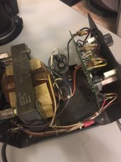
 Looking a little gray around the edges!
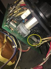
![WP_20160125_19_03_11_Pro[1].jpg](/forum/data/attachments/99/99004-c590bd2e0edb562f6d4f7e1313ae14af.jpg)
![WP_20160125_19_02_54_Pro[1].jpg](/forum/data/attachments/99/99005-dacd1a855c9f20a0239ae46263de1142.jpg)