• Welcome to Photrio!
    Registration is fast and free. Join today to unlock search, see fewer ads, and access all forum features.
    Click here to sign up

Build: A calibrated white light sensitometer

Recent Classifieds

Forum statistics

Threads
202,851
Messages
2,846,576
Members
101,570
Latest member
Justgregor
Recent bookmarks
0

reneboehmer

Subscriber
Allowing Ads
Joined
Oct 6, 2024
Messages
258
Location
Austria
Format
Analog
1 Introduction

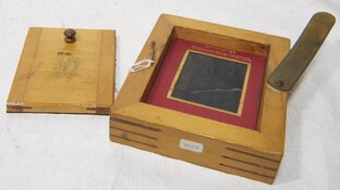
When working with analog materials, one of the key instruments used is a sensitometer. It is
used to expose a piece of light-sensitive material with a known amount of electromagnetic energy.
The spectral characteristics of which depend on what specific material shall be exposed.
When working with black-and-white silver halide films, the spectral properties are defined in
International Standard ISO 7589:2002 — Photography — Illuminants for sensitometry — Spec-
ifications for daylight, incandescent tungsten and printer.


2 ISO 7589

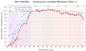
To test black-and-white film, a sensitometer’s light source should simulate real-world conditions.
In this case, this means that a source with a specific photographic daylight spectrum (D55),
modulated by the spectral transmittance of an ISO standard camera lens, shall be used.
The usability of a source is defined by the use of a Spectral Distribution Index (SDI) score
system, which defines RGB index tolerances of:
• Blue must not differ from Green by more than ± 4
• Red must not differ from Green by more than ± 3

3 Goal

Needed is to build a calibrated sensitometer that allows absolute film speed calculation. The
unit shall give a repeatable and exact amount of predefined illuminance over a repeatable and
exact amount of time. The device should be able to perform easy self-calibration by the use of an
external calibrated lux meter, that measures illuminance at direct contact with the light source
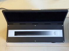
surface. The software of the unit should handle the calibration of a step wedge used, taking into
consideration the transmittance of each field of the step wedge, and then informing the user of
the absolute illuminance at any given point. This allows the user to read absolute illuminance,
without flare, reaching the film surface from a table generated by the unit.


4 Plan and Assumptions

Building a sensitometer light source that is in spec with ISO 7589 is not the target of this project.
The target is to build a functioning unit that is calibrated and as close to ISO 7589 as reasonably
achievable.
Since this unit will not be used as a colour sensitometer, given tolerances can be assumed to
be much lower. Spectral power distribution of the light source is of course important, but the
sensitivity shift that can be expected by not exactly adhering to ISO 7589 is most likely negligible.
The reason why ISO 7589 is not followed exactly has to do with the comfort of using off-the-shelf
LED light sources. It is possible to meet the ISO SPD characteristics with custom LED arrays
and drivers, but not without expensive time and money investment.
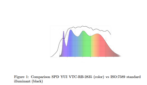
We are assuming that high-quality 5600 K LEDs with a CRI of 98 are sufficiently close to an
ISO light source that further improvements would only result in marginal positive impact.
We also assume that SPD does not change in a relevant way when PWM dimming these LEDs.
We further assume that high-frequency (20 kHz) PWM dimming does not result in reciprocity-
related effects in silver halide materials, as the off-period duration (∼12.5 μs at 50% duty) falls
well within the persistence window of latent sub-image centres.

5 Parts

All parts are off-the-shelf, not requiring any custom PCB work. It was important to us that this
unit was easy to build, as it would allow others to replicate the sensitometer easily.
• ESP32 + breakout board
• USB-C PD board (20 V)
• Variable step-up converter (20 V to 24 V for LEDs)
• Variable step-down converter (20 V to 5 V for ESP32)
• MOSFET with PWM capability
• Button
• LEDs — Yuji VTC-RB-2835-24V
• Custom-cut flashed opal glass

The cat design was done by my friend Angelo, I can't take credit for this.


IMG_6452.jpg
 

Attachments

  • IMG_6451.jpg
    IMG_6451.jpg
    1 MB · Views: 57
  • 1771684240536.png
    1771684240536.png
    280.5 KB · Views: 51
  • 1771684478609.png
    1771684478609.png
    56.3 KB · Views: 53
  • WhatsApp Image 2026-03-19 at 17.30.03.jpeg
    WhatsApp Image 2026-03-19 at 17.30.03.jpeg
    173.5 KB · Views: 56
Last edited:
Sources of Error

7.1 Exposure Timing
Repeatability of exposure time. The ESP32 timer resolution and MOSFET switching speed
introduce a finite uncertainty in actual exposure duration. At short exposure times this becomes
proportionally more significant.

7.2 Illuminance Stability
Repeatability of illuminance. LED output is a function of junction temperature. After power-
on, the LED junction heats up and luminous flux drops until thermal equilibrium is reached. A
warm-up period must be accounted for, or the illuminance will drift between exposures. Ambient
temperature changes between sessions will also shift the operating point.

7.3 Spectral Stability
Repeatability of spectral conditions. While PWM dimming preserves SPD at a given duty cycle,
LED phosphor emission does shift slightly with junction temperature. Over the lifetime of the
LEDs, phosphor degradation and die aging may cause gradual SPD drift.

7.4 Power Supply Regulation
The USB-C PD source and step-up converter introduce voltage regulation tolerances. Ripple
on the 24 V rail modulates LED forward current between PWM pulses, affecting instantaneous
luminous flux.

7.5 Lux Meter Spectral Mismatch
The calibrated lux meter weights incoming light by the CIE V (λ) photopic luminosity function,
not by the spectral sensitivity of silver halide film. Any deviation of the LED SPD from the
calibration illuminant of the lux meter introduces a systematic offset between measured and
actual photographic exposure.

7.6 Opal Glass Uniformity
Spatial non-uniformity of the flashed opal glass diffuser causes the illuminance field across the
film gate to vary. Edge-to-centre fall-off and local thickness variations directly affect step wedge
field exposures at different positions.

7.7 Step Wedge Calibration
The nominal density values of the step wedge carry their own measurement uncertainty. Ad-
ditionally, neutral-density filters are never perfectly spectrally flat — the actual transmittance
varies with wavelength, meaning the effective density seen by a panchromatic film may differ
from the density measured by the calibration instrument.

7.8 Geometric Alignment
Any air gap or angular misalignment between the opal glass, step wedge, and film plane intro-
duces the possibility of light spreading between adjacent step wedge fields. This inter-field flare
contaminates the lower-density steps in particular.

7.9 Stray Light
Internal reflections within the sensitometer housing can add unwanted exposure to the film
surface, particularly in the shadow (high-density) region of the step wedge. This acts as a
flare-like offset that compresses the measured density range.

8.0 Nonlinearity of Swtiching
Non linearity of PWM low end switching. Linearity can not be maintained in extrem switching scenarios
due to hardware limitations. Can be somewhat corrected in software calibration but limits exposure times / intensities.
 
That’s a beautiful project! Are you giving 1/100 second exposures?

The unit auto adjusts the time. Its also user definable. 1/100 is possible yes.

Atm I only input ISO of the film I use, and the unit decides an exposure time for me based on the step wedge I registered in the software. It will keep the exp. times in a frame so that potential reciprocity problems don't occur.

It will dim the light if needed. I use PWM dimming which, I assume, does not significantly change spectral properties of the source.
 
I think PWM dimming may be criticized as violating the requirement “non-intermittent”.

Can you engineer a physical dimmer? EG&G implements acetate filters with opaque grid lines.

p.s. Kodak used to criticize EG&G for using xenon electronic flash for violating the requirement "continuous spectrum".

2026-03-19-0001.jpg
 
Impressive project. Congrats.

I made something similar (not anywhere near as tidy) but in the end opted not to use PWM attenuation although in practice it's likely a non issue.
 
I was thinking about using PWM or constant voltage. As far as I understand it there is an inherit inertia threshold in the photon transfer of the silver halide. If the frequency / intensity doesn't cross that threshold, the film will “see” the light as continuous. With a frequency of 20khz I should be orders of magnitudes away from said point. I plan to test this in the future by comparing constant voltage tests vs different PWM frequencies. I will share results here in this forum.
 
I think PWM dimming may be criticized as violating the requirement “non-intermittent”.

Can you engineer a physical dimmer? EG&G implements acetate filters with opaque grid lines.

It shouldn't be an issue to dim voltage instead of flashing. But my initial fear was extreme dimming over voltage might shift spectral properties. I think PWM should be fine tho. As mentioned above, Ill try to test it and compare results
 
It shouldn't be an issue to dim voltage instead of flashing. But my initial fear was extreme dimming over voltage might shift spectral properties. I think PWM should be fine tho. As mentioned above, Ill try to test it and compare results

Are you using a single LED or a line of them? The EG&G has the challenge that the distance from central bulb to platen is 5% farther at the edges than center. Some models come with a curved platen to solve this issue.
 
Are you using a single LED or a line of them? The EG&G has the challenge that the distance from central bulb to platen is 5% farther at the edges than center. Some models come with a curved platen to solve this issue.

a line of leds
 
Can you put a clock in it to mark the date and time of exposure?

That’s a data point I keep missing in my sensitometry.

p.s. I have you to thank for this new addition to my lab.
IMG_4295.jpeg
 
Can you put a clock in it to mark the date and time of exposure?

My friend also made that suggestion. We thought of a small LCD that could expose details. I wasn't sure about it tho and figured I'd first go the way of minimal viable product. :smile:
p.s. I have you to thank for this new addition to my lab.
Nice! It's great to keep track of fluid density. Not a hard measurement to make and not expensive eighter!
 
I was thinking about using PWM or constant voltage.

But my initial fear was extreme dimming over voltage might shift spectral properties.

Constant voltage is not a good idea, because (1) the I/V characteristic of LEDs is grossly non-linear and extremely steep, and (2) constant voltage does not guarantee constant light output due to thermal effects. Constant current is a different matter and can indeed work. It's not horribly complicated to make a servo using an opamp and a reference voltage to make a controllable constant current regulator that you can control from the ESP32 software.

As to spectral characteristics: as long as you remain a safe thermal envelope for the LED, the spectral properties will not change in any meaningful way.

7.4 Power Supply Regulation
The USB-C PD source and step-up converter introduce voltage regulation tolerances. Ripple
on the 24 V rail modulates LED forward current between PWM pulses, affecting instantaneous
luminous flux.
This will cease to be an issue if you move to constant current drive. In the present situation it is most likely not a significant issue. If you want to hedge against it, add something like 220uF to the +24V rail. But honestly - not necessary. It's fine as it is.

The project box looks nice! Angelo did a great job on it.

As to the PWM issue - I don't expect it's an issue, but as you know, we so far have no concrete data on the quantitative side of the intermittency effect. There are also MOSFET switching issues if you move to very high PWM frequencies that will affect linearity esp. for very low duty cycles. So the trick is likely to hit a sweet spot in terms of frequency and avoid very low duty cycles altogether.

One thing that might work, but will add considerable complexity, is to include a light integrator into the sensitometer and use it to control the actual exposure given by the light source. Regardless of how the light source is switched, this could help to achieve consistent exposures. However, I emphasize that it will make things far more complex than they are now, and it's contestable whether the net effect (in terms of any accuracy gains) is going to be meaningful.

I'd be inclined to just do some test runs with the device as it is and compare the results with known data from the films used. As long as you're close...well, you're close.
 
Can you show the light box? I started a small sensitometer collection about 20 years ago and each device solves the even illumination problem in a totally different manner.
 
IMO /assuming/ that intermittency does not matter is not consistent with the quality of the rest of the design.

A little less complex than the integrator mentioned by @koraks would be: current drive with analog feedback from a photodiode. No switching transients, heating effects of the LED are absorbed. Timiing provided by processor.
 
I think the LCD would be great for it. Having seen ic-racer’s sensitometer shootout and seeing significant latent image degradation effects, I think marking timestamp is more critical than light source falling short of ideal.

A standalone edge stamper would be good too
 
Can you show the light box? I started a small sensitometer collection about 20 years ago and each device solves the even illumination problem in a totally different manner.

Its a simple design. A white matt box, that has one opal glass sitting about 1cm above the leds and another one about 6cm above the leds. The glass I used is flashed opal glass from a German company. I have slight falloff to the very left and right, because the leds are not longer than the illumianted surface. The fall of vertically is not measureable with my current tools. The horizontal usable area is a little longer than the stouffer T4110. I will post a picture later. Should I find any inaccuracy of the light soruce Ill probably calibrate it out in software and assign a fixed mounting place for the step wedge i use.
 
IMO /assuming/ that intermittency does not matter is not consistent with the quality of the rest of the design.
I dont assume intermittency to not matter. I just think that at the duty cycle of my switching together with the afterglow of the led phosphor, there is not enough time for the photontransfer to degrade. At lower freuqencies yes, this is an issue but at 20khz i doubt it is. But I will test it and put the measurments relative to a lightsource running on constant voltage, just to be sure.

A little less complex than the integrator mentioned by @koraks would be: current drive with analog feedback from a photodiode. No switching transients, heating effects of the LED are absorbed. Timiing provided by processor.

I was thinking of including something like this in the future. For now i wanted to have a minimal viable product i could start to test with.
 
Photrio.com contains affiliate links to products. We may receive a commission for purchases made through these links.
To read our full affiliate disclosure statement please click Here.

PHOTRIO PARTNERS EQUALLY FUNDING OUR COMMUNITY:


Ilford ADOX Freestyle Photographic Stearman Press Weldon Color Lab Blue Moon Camera & Machine
Top Bottom