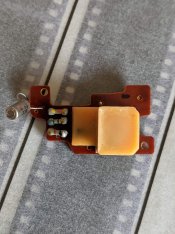
Yashica Electro 35 misbehaving from f8 ->f16

Custom Cab

A
Custom Cab

  • 1
  • 1
  • 14
Table for four.

H
Table for four.

  • 9
  • 0
  • 85
Waiting

A
Waiting

  • 5
  • 0
  • 80
Westpier

A
Westpier

  • 3
  • 2
  • 86
Westpier

A
Westpier

  • 5
  • 0
  • 63

Recent Classifieds

Forum statistics

Threads
197,594
Messages
2,761,607
Members
99,410
Latest member
lbrown29
Recent bookmarks
0

Jonno85uk

Member
Joined
Dec 15, 2020
Messages
188
Location
England
Format
Multi Format
I have an Electro 35 GSN that for the most part works fine. However, when I use f8 -> f16 it often chooses to use overly long shutter speeds. F8 setting being the worst. For example of what i'm experiencing - f5.6 normal shutter speed with no slow shutter speed indicator. F8 ~1/2s. F11 ~1/4s.

It's been almost 15yrs since I last took apart an Electro lens so I can't exactly remember what was in it but is this problem an issue with bad contacts or failed resistors (i think that what was inside the lens on each aperture setting)?
 
OP
OP

Jonno85uk

Member
Joined
Dec 15, 2020
Messages
188
Location
England
Format
Multi Format
OP
OP

Jonno85uk

Member
Joined
Dec 15, 2020
Messages
188
Location
England
Format
Multi Format
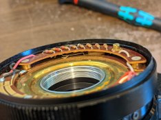
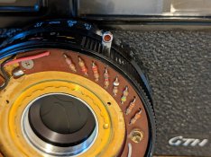
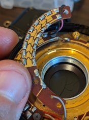
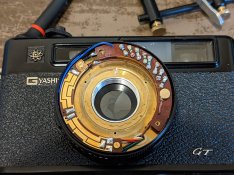
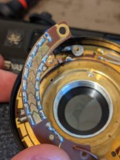
I finally got round to having a look at this.
It was considerably easier to dissamble than I remembered. Unfortunately, contacts weren't that dirty. resistances ~matched the colour codes and the resistances along the various contacts of the variable resistor were fine.
Issue remained after cleaning.

Looking at the repair manual my next suspect is the timing capacitor. I wonder what type it is. Old caps (electrolytic) are always suspect (ESR).

I also discovered my spare "GSN" is a GT and the winder off my GTN doesn't fit it. Also seems to be dead (battery indicator does nothing). I have plans to do some modding to this in the future knowing its status now.

PXL_20210810_184231003.jpg PXL_20210810_185338197.jpg PXL_20210810_190110686.jpg
 
Last edited:

Donald Qualls

Subscriber
Joined
Jan 19, 2005
Messages
12,102
Location
North Carolina
Format
Multi Format
Ceramic caps haven't changed in more than fifty years, and tantalum were new after that camera was built, so if they're not ceramic, they're probably electrolytic. There were rolled foil caps back in the 1960s and before, but those are too bulky to show up in most cameras.
 
OP
OP

Jonno85uk

Member
Joined
Dec 15, 2020
Messages
188
Location
England
Format
Multi Format
Judging by the cap values I've seen via googling (it varies) it's almost certainly to be electrolytic. I'm hoping this is the culprit. Hopefully the value marking isn't cryptic
 

Donald Qualls

Subscriber
Joined
Jan 19, 2005
Messages
12,102
Location
North Carolina
Format
Multi Format
Hopefully the value marking isn't cryptic

Yeah, no doubt. "Oh, don't you have the factory drawings to know a cap with 14H on it is .1 microfarad?"
 
OP
OP

Jonno85uk

Member
Joined
Dec 15, 2020
Messages
188
Location
England
Format
Multi Format
I can't see it's the capacitor. If there was a problem with it then it would affect all apertures. You have a bad contact somewhere in the lens.
That's why I thought it was a contact to begin with.
I've checked each aperture-ring contact summing up the resistance values for each segment. They all added up correctly. I inspected the solder joins of the resistors and none looked suspicious. I guess I could go over the contacts with a PCB eraser to be sure although that's probably a bad idea with the gold-plating.

Is there any other contact I should be checking? AFAIK, there's the mode selecting contacts (the mode selector and contact bridging it to the aperture-ring), which was filthy in the flash segment, but cleaning made no difference.

The schematic i've been referring to:
electr_schm.jpg
 
Last edited:
OP
OP

Jonno85uk

Member
Joined
Dec 15, 2020
Messages
188
Location
England
Format
Multi Format
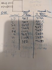
As it was simple enough to disassemble, I rechecked the aperture-ring resistor but this time taking into account the sliding contacts.

I measured between top/bottom of the variable resistor and the slider contact (the trace for 'A' of the function switch).
Nothing odd was seen. The values increased in line with the measured+displayed values of each resistor (not the same values in the schematic attached).
 
Last edited:
OP
OP

Jonno85uk

Member
Joined
Dec 15, 2020
Messages
188
Location
England
Format
Multi Format
As you have another camera, have you tried comparing measured values with that? It might show up some differences that lead you to the problem.

I've realised i've got the models wrong earlier. The spare is a GT. The one with the issue is a GTN. The GTN allowed use of ISO speeds up to 1000 whereas the others allowed up to 500.

I measured anyway and the values matched the GS listed values.
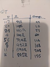
PXL_20210813_184701186.jpg PXL_20210813_184824161.jpg PXL_20210813_190619315.jpg

The GTN values for reference (please excuse the scrawling)
PXL_20210813_191244156.jpg PXL_20210813_191249702.jpg
Although i've denoted the tolerance bands as Silver, they could be grey. It was hard to make out. I do notice the pictures show them as gold. It's possible that's what they are.
 
Last edited:

monopix

Member
Joined
Dec 10, 2009
Messages
146
Location
Lincolnshire, UK.
Format
Hybrid
I'm a bit confused by the values you've measured because they don't match the values on the GS circuit diagram. But what's clear is the GS and the GT seem to use the same resistor values but the GTN uses different values so comparing the two isn't valid.

I'm not sure where you measured the values on the GTN. The resistor board wiper also wipes along a solid track on the board below to make the connection back to the function switch. Have you cleaned that track? Did you include that track in your measurements? Would be worth cleaning all the tracks if you haven't using a fibreglass PCB cleaner pen (it won't damage the gold).

Another thought. What battery are you using and have you monitored the battery voltage while operating the camera. The suggested alternative batteries for these are generally inadequate and can't deliver the required current. I did a lot of testing of different batteries a while back. You can read the results at https://www.contax139.co.uk/replacement-battery-for-yashica-electro-35-series. I did my testing with a GT and it largely worked but maybe the GTN behaves differently as the circuit values are different.
 
OP
OP

Jonno85uk

Member
Joined
Dec 15, 2020
Messages
188
Location
England
Format
Multi Format
I'm not sure where you measured the values on the GTN. The resistor board wiper also wipes along a solid track on the board below to make the connection back to the function switch. Have you cleaned that track? Did you include that track in your measurements? Would be worth cleaning all the tracks if you haven't using a fibreglass PCB cleaner pen (it won't damage the gold).

Another thought. What battery are you using and have you monitored the battery voltage while operating the camera. The suggested alternative batteries for these are generally inadequate and can't deliver the required current. I did a lot of testing of different batteries a while back. You can read the results at https://www.contax139.co.uk/replacement-battery-for-yashica-electro-35-series. I did my testing with a GT and it largely worked but maybe the GTN behaves differently as the circuit values are different.

In a previous reply I mentioned where I was taking the values from; between the trace back to the function board (solder blob of jumper wire) and the exposed leg of top-most/bottom-most resistor.

Batteries was my other concern so I had replaced with some new energizer lr44s but that made no difference. I could measure the voltage and see if it drops significantly.

That reminds me of one thing I have noticed, and it may be voltage related, is that on very long exposures, something buzzes just before the shutter closes. I'm not sure what else that could be other than the shutter solenoid.
 
OP
OP

Jonno85uk

Member
Joined
Dec 15, 2020
Messages
188
Location
England
Format
Multi Format
I just read the link you posted. Voltage drop seems a possibility. I had a thought earlier that Im not sure what resistance is seen by the cameras circuit at f8+.

Looking at the circuit now and with the resistances I measured, the resistance almost halves at f8.
 

Nicholas Lindan

Advertiser
Advertiser
Joined
Sep 2, 2006
Messages
4,219
Location
Cleveland, Ohio
Format
Multi Format
The schematic above makes little sense in the details but I suppose provides a sort of overview.

I'm a bit confused though - do the resistor values on the camera with the problem match the schematic?

I would suspect that if it isn't a contact problem then a transistor may have lost gain. That's not that uncommon in mid-60's plastic packaged transistors.

Any markings on the transistors? It is possible that one or more were gain selected - as evidenced by the presence of a thermistor to try and hold the gain steady over temperature.

The usual 'universal' replacements are the 2N3904 (for NPN, arrow pointing out) and 2N3906 (for PNP, arrow pointing in (TR-2)). If it were my camera, and the circuits were similar, I'd try replacing TR-1 with a 2N3904 and see what happens.

Can you provide pictures of the electronics control board - both sides?

But I would still suspect contacts. Try springing the wipers up a wee bit. You could measure the voltage at the wiper return wire as the aperture changes. If the schematic is half-way correct it should be steadily increasing as you go towards f16. The camera needs to be on and the shutter button part-way depressed (i.e. 'red' or 'yellow' position) (again trusting the schematic somewhat).
 
Last edited:
OP
OP

Jonno85uk

Member
Joined
Dec 15, 2020
Messages
188
Location
England
Format
Multi Format
The schematic above makes little sense in the details but I suppose provides a sort of overview.

I'm a bit confused though - do the resistor values on the camera with the problem match the schematic?

I would suspect that if it isn't a contact problem then a transistor may have lost gain. That's not that uncommon in mid-60's plastic packaged transistors.

Any markings on the transistors? It is possible that one or more were gain selected - as evidenced by the presence of a thermistor to try and hold the gain steady over temperature.

The usual 'universal' replacements are the 2N3904 (for NPN, arrow pointing out) and 2N3906 (for PNP, arrow pointing in (TR-2)). If it were my camera, and the circuits were similar, I'd try replacing TR-1 with a 2N3904 and see what happens.

Can you provide pictures of the electronics control board - both sides?

But I would still suspect contacts. Try springing the wipers up a wee bit. You could measure the voltage at the wiper return wire as the aperture changes. If the schematic is half-way correct it should be steadily increasing as you go towards f16. The camera needs to be on and the shutter button part-way depressed (i.e. 'red' or 'yellow' position) (again trusting the schematic somewhat).
I had the same thought about the wipers.
The wipers have plenty of tension. They push the resistor board off once unscrewed.

The transistors are potted, of sorts. I remember a presentation by Bill Herd about the problems of protecting silicon from the environment in the past.

The resistor values on the gtn are different than the GT/GS. Presumably to account for increased ISO capability.

It's not possible to get a view of this board. It requires desoldering the wires and CDS off.
 

monopix

Member
Joined
Dec 10, 2009
Messages
146
Location
Lincolnshire, UK.
Format
Hybrid
The schematic above makes little sense in the details but I suppose provides a sort of overview. The schematic is, of course, for a different though similar camera.

The cct dia is quite accurate apart from one glaring mistake by whoever drew it, they have the negative of the battery and battery check cct connected the wrong side of the diode.

There's at least three different versions of the pcb. The early ones are potted so you can see nothing. Later ones have an open pcb and the latest version uses a custom chip. I suspect the one the op has is the one with a custom chip as the manual refers to the different resister values totalling 10k which matches those measured.
 

Nicholas Lindan

Advertiser
Advertiser
Joined
Sep 2, 2006
Messages
4,219
Location
Cleveland, Ohio
Format
Multi Format
I had the same thought about the wipers.
The wipers have plenty of tension. They push the resistor board off once unscrewed.

Well, that leaves the control circuit board as the only logical suspect.
 

Nicholas Lindan

Advertiser
Advertiser
Joined
Sep 2, 2006
Messages
4,219
Location
Cleveland, Ohio
Format
Multi Format
The cct dia is quite accurate apart from one glaring mistake by whoever drew it, they have the negative of the battery and battery check cct connected the wrong side of the diode.

Yup, that was what caused me to suspect the whole thing. And the resistor values in one of the photos being very different. Not exactly a great bit of circuit design.
 
OP
OP

Jonno85uk

Member
Joined
Dec 15, 2020
Messages
188
Location
England
Format
Multi Format
I found that diagram here. https://www.flickr.com/groups/44787261@N00/discuss/72157677658285107/

Interestingly he changed the original diode orientation to what you see now.

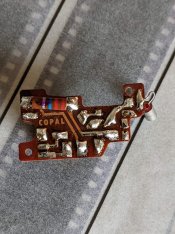
For reference, and because you asked, here is the circuit board, albeit from the GT, not the GTN which is the problematic camera in question.

PXL_20210814_174229795.jpg PXL_20210814_174237414.jpg
During stripdown, i found a few issues as to why the GT was sold as a spares camera. The shutter-release switch (3/3 switch of the L-shaft) wasn't working, winder was being interfered by the plastic counter window and the battery-tester was inoperable because a wire had come off the bulb.
 
Last edited:
OP
OP

Jonno85uk

Member
Joined
Dec 15, 2020
Messages
188
Location
England
Format
Multi Format
Just as a sanity test, I did an exposure test where all I did was change aperture at a static scene.
The "dark" images are I think up to f4 (didn't take into account fogged leader of hand-loaded film) which is odd. Although, up until now I have only been checking this issue pointing my camera at the sky.

The first overexposed frame is more overexposed than the next 2 but the 1st 3 appear consistent.

2021-08-14-0001.jpg


@monopix Do you have a suggestion on how to measure the voltage drop? As in placement of probes fairly easily? From dismantling the GT I know where to get to +ve (underneath bottom plate is easiest) but the -ve is one of the few white wires in the rats-nest.

I couldn't think of anything quick so I put a CR123A battery inside instead. Amazingly the camera still operated at 3V (without lamps) but the odd exposure time issue remained.
 

Bob Palmieri

Member
Joined
Dec 5, 2021
Messages
4
Location
Chicago
Format
35mm RF
Hey Folks!

Just got my first Electro 35. Amusingly, it's basically displaying what I'd consider the opposite misbehavior. F/8 - F/16 seem to produce reasonable-sounding shutter speeds, but 1.7 - 5.6 just default to 1/500 or so. Really thought it must be the resistor array, so went in, cleaned contacts and measured resistances.. No change...

Anyone have a call on this?

PART DEAUX: Pulled the bottom plate, squirted some DeOxit kindof "at" the circuit board with contacts actuated by the release shaft and she's come around!

Next round I might just clean & tighten the appropriate spring so that the shutter opens all the way. Right now we're good all the way out to f/2, which is good enough to shoot a roll of film!
 
Last edited:
Photrio.com contains affiliate links to products. We may receive a commission for purchases made through these links.
To read our full affiliate disclosure statement please click Here.

PHOTRIO PARTNERS EQUALLY FUNDING OUR COMMUNITY:


Ilford ADOX Freestyle Photographic Stearman Press Weldon Color Lab Blue Moon Camera & Machine
Top Bottom