

AndrewBurns
Member
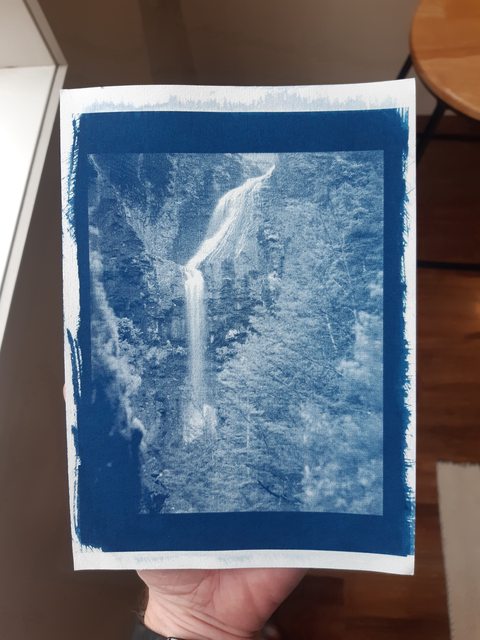
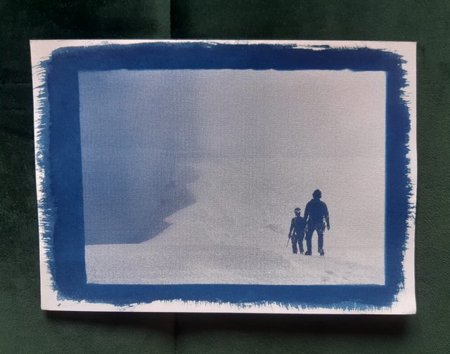
Earlier this year I attempted to use a modified laser cutter (fitted with a low-power 405nm UV laser) to make alternative process prints. I started with Cyanotypes as they presented a fairly fast and easy way to test my process. Long story short my laser exposure process worked but it was painfully slow and fairly low resolution, and I figured that the amount of work required to make it reasonably fast and high-quality just wasn't worth it. These are some of the best results I got (each of these A5 sized prints took more than 2 hours to make).
At the time some people recommended I look at the monochrome screens and UV exposure units used in resin 3D printers, and so I did some research and the concept seemed feasible. For some background, resin 3D printers use a tub of UV-sensitive polymer which is hardened by exposure to UV light that passes through an LCD screen. Mask images are displayed on the LCD screen to selectively harden only some of the resin, and multiple masks are shown one after the other to build a 3D part.
Before going any further, a number of people on this forum have already been using similar LCD screens in normal enlargers for silver printing with good results, there's a lot of detail to be had in the following thread: https://www.photrio.com/forum/threads/diy-31-megapixel-enlarger.197305/
The big difference with what I'm doing is using the screen for contact printing and with UV so I could make alt-process prints.
2D photo printing isn't exactly the same as 3D resin printing though, so the big questions I had were:
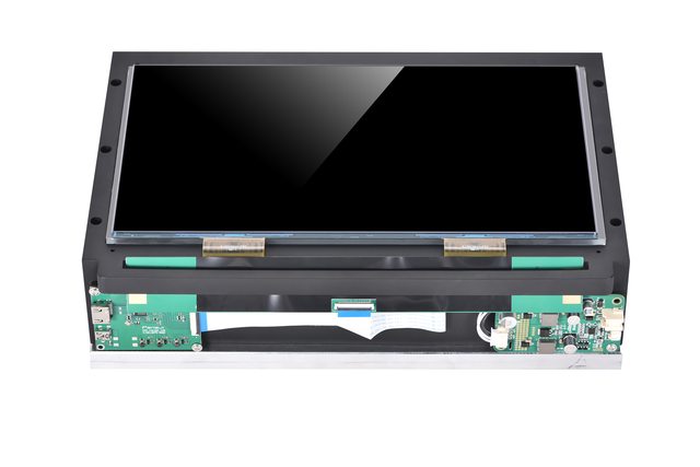
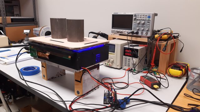
This is the unit I bought, the aliexpress link is as follows: https://www.aliexpress.com/item/1005004111440256.html
The active area of the screen measures 298x165mm, it displays 6480x3600 pixels (roughly 23Mp) and when used for contact printing theoretically results in 552 dpi on the page, which should be more than enough. It's a monochrome screen which means each pixel can only show shades of grey, but this means it transmits UV light significantly better than an RGB screen would as there are no colour filters in the way.
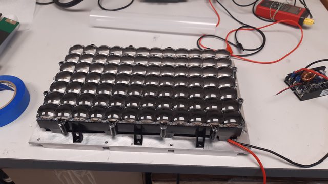
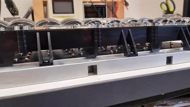
The UV lamp is comprised of 84 405nm UV LED's with a large grid-shaped collimating lens in front of them. I haven't measured the power consumption but it's on the order of 200W+. It's extremely powerful and the output is well collimated, you can immediately feel your skin heating up when exposed to the light through a blank LCD screen (and keep in mind the screen already blocks nearly 90% of the UV light power).
My exposure time for traditional cyanotypes using this screen and light-source is around 4 minutes after adding a diffuser (more on that later). The rated life of the screen is >2000 hours when exposed to this much UV energy, which works out to something like 22,000 prints so I figure it's not really going to be a problem.
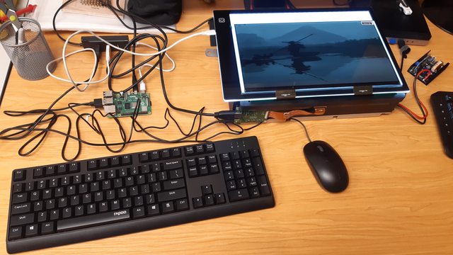
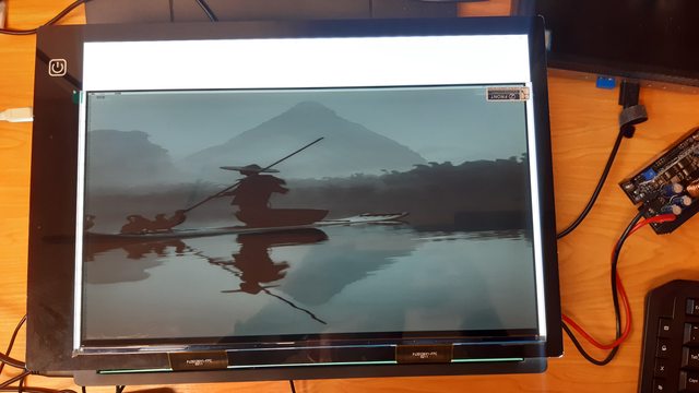
In order to actually drive the screen I needed to send it something over HDMI, so I bought a raspberry pi 4 computer and hooked it up. In the following photos I had an LED tracing pad behind the LCD screen so that I could see what it was doing.
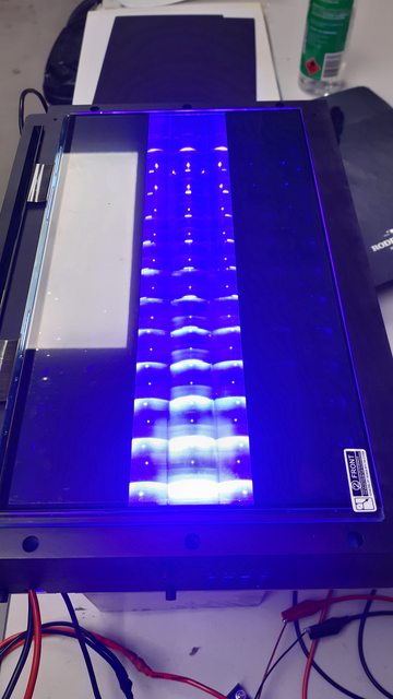
And here's a view of the UV light shining through the screen with a strip along the middle set to clear while the rest of the screen is showing full black (plus a reflection from an overhead light).
Using the screen in this arrangement is simply a matter of displaying a picture of the negative on the computer in 'fullscreen' mode and then turning the UV light on. I'm currently performing this all manually, but in the future I'll write a program to automatically display the image and turn the light on for the correct length of time (or UV integration). I place my sensitised paper face-down on the LCD screen, put a piece of soft foam on top, then a piece of wood and some weights to keep the paper flat against the screen.
It's covered in the other Photrio thread I linked to at the start of this post, but sending an image to the screen isn't as simple as you might first think. Because it's a monochrome screen there aren't any RGB sub-pixels, so instead each R, G and B colour value actually controls the density of 3 physical pixels. The end result is that to send an image to the screen and have it look correct you first need to compress it by a factor of 3 in the horizontal axis and convert the compressed pixel greyscale values into colours. The resulting squashed and colourised image looks terrible on a normal screen but displays perfectly on the monochrome screen.
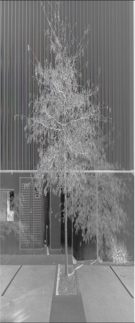
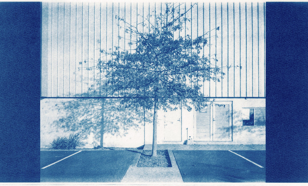
This squashed image is what gets sent to the screen (also inverted to be a negative and flipped) and this was the resulting print:
I think that this is a large enough post for now so I'll cover all of the other steps I've had to go through to get to that result along the way and I'll share the python script that I'm currently using to convert the image for display. The major topics I'll cover in future posts are:
At the time some people recommended I look at the monochrome screens and UV exposure units used in resin 3D printers, and so I did some research and the concept seemed feasible. For some background, resin 3D printers use a tub of UV-sensitive polymer which is hardened by exposure to UV light that passes through an LCD screen. Mask images are displayed on the LCD screen to selectively harden only some of the resin, and multiple masks are shown one after the other to build a 3D part.
Before going any further, a number of people on this forum have already been using similar LCD screens in normal enlargers for silver printing with good results, there's a lot of detail to be had in the following thread: https://www.photrio.com/forum/threads/diy-31-megapixel-enlarger.197305/
The big difference with what I'm doing is using the screen for contact printing and with UV so I could make alt-process prints.
2D photo printing isn't exactly the same as 3D resin printing though, so the big questions I had were:
- How large of a print can I make (how big of a screen is available)
- How fast will the exposure time be
- What kind of resolution could I expect
- What sort of lifetime will the screen have
This is the unit I bought, the aliexpress link is as follows: https://www.aliexpress.com/item/1005004111440256.html
The active area of the screen measures 298x165mm, it displays 6480x3600 pixels (roughly 23Mp) and when used for contact printing theoretically results in 552 dpi on the page, which should be more than enough. It's a monochrome screen which means each pixel can only show shades of grey, but this means it transmits UV light significantly better than an RGB screen would as there are no colour filters in the way.
The UV lamp is comprised of 84 405nm UV LED's with a large grid-shaped collimating lens in front of them. I haven't measured the power consumption but it's on the order of 200W+. It's extremely powerful and the output is well collimated, you can immediately feel your skin heating up when exposed to the light through a blank LCD screen (and keep in mind the screen already blocks nearly 90% of the UV light power).
My exposure time for traditional cyanotypes using this screen and light-source is around 4 minutes after adding a diffuser (more on that later). The rated life of the screen is >2000 hours when exposed to this much UV energy, which works out to something like 22,000 prints so I figure it's not really going to be a problem.
In order to actually drive the screen I needed to send it something over HDMI, so I bought a raspberry pi 4 computer and hooked it up. In the following photos I had an LED tracing pad behind the LCD screen so that I could see what it was doing.
And here's a view of the UV light shining through the screen with a strip along the middle set to clear while the rest of the screen is showing full black (plus a reflection from an overhead light).
Using the screen in this arrangement is simply a matter of displaying a picture of the negative on the computer in 'fullscreen' mode and then turning the UV light on. I'm currently performing this all manually, but in the future I'll write a program to automatically display the image and turn the light on for the correct length of time (or UV integration). I place my sensitised paper face-down on the LCD screen, put a piece of soft foam on top, then a piece of wood and some weights to keep the paper flat against the screen.
It's covered in the other Photrio thread I linked to at the start of this post, but sending an image to the screen isn't as simple as you might first think. Because it's a monochrome screen there aren't any RGB sub-pixels, so instead each R, G and B colour value actually controls the density of 3 physical pixels. The end result is that to send an image to the screen and have it look correct you first need to compress it by a factor of 3 in the horizontal axis and convert the compressed pixel greyscale values into colours. The resulting squashed and colourised image looks terrible on a normal screen but displays perfectly on the monochrome screen.
This squashed image is what gets sent to the screen (also inverted to be a negative and flipped) and this was the resulting print:
I think that this is a large enough post for now so I'll cover all of the other steps I've had to go through to get to that result along the way and I'll share the python script that I'm currently using to convert the image for display. The major topics I'll cover in future posts are:
- Diffusing the light source so that it gives even tones without making the image overly soft
- Linearising the cyanotype process to give a good output
- Limitations of the system and how I plan to work around them (primarily print size and dynamic range)


